For 1990-2009 cars only
Air Inlet Assembly Replacement Left Hand Drive
Removal Procedure
- Remove the instrument panel (I/P) compartment. Refer to Instrument Panel Compartment Replacement .
- Remove the closeout panel. Refer to Instrument Panel Insulator Panel Replacement - Right Side .
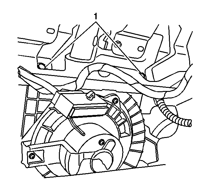
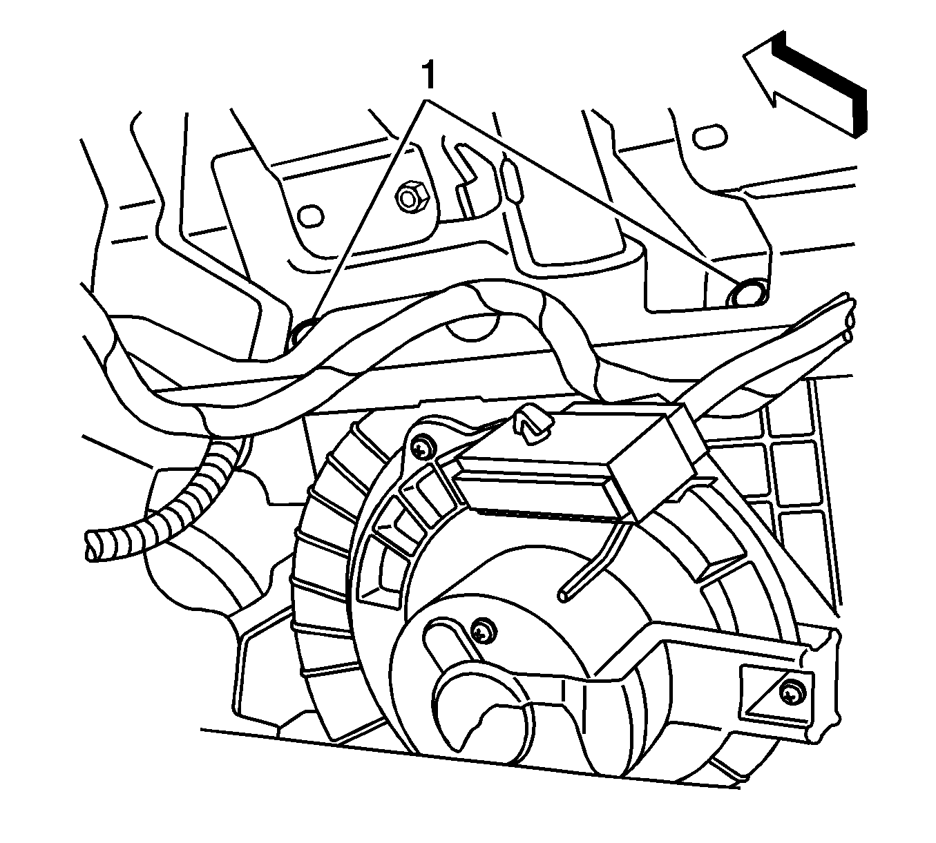
- Remove the upper air inlet assembly bolts (1).
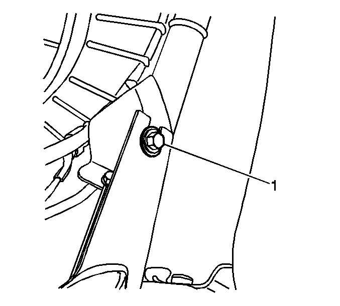
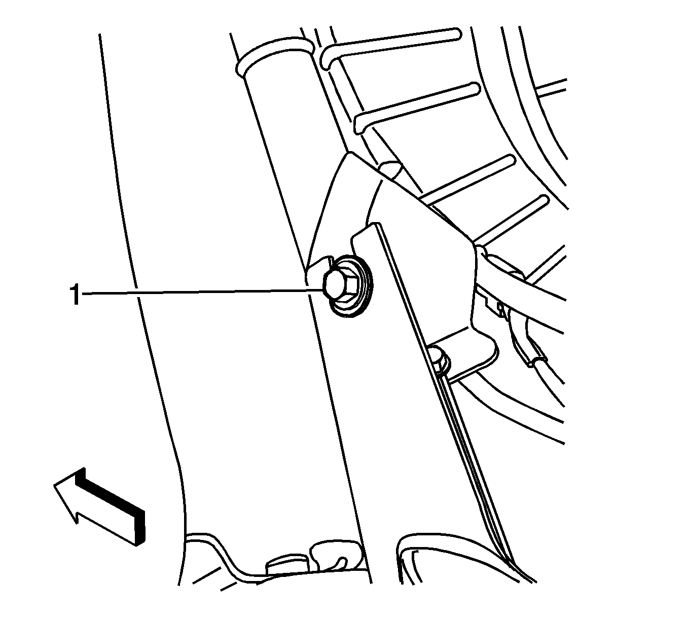
- Remove the lower right air inlet assembly bolt (1).
- Slide the assembly to the right and then lower.
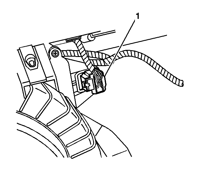
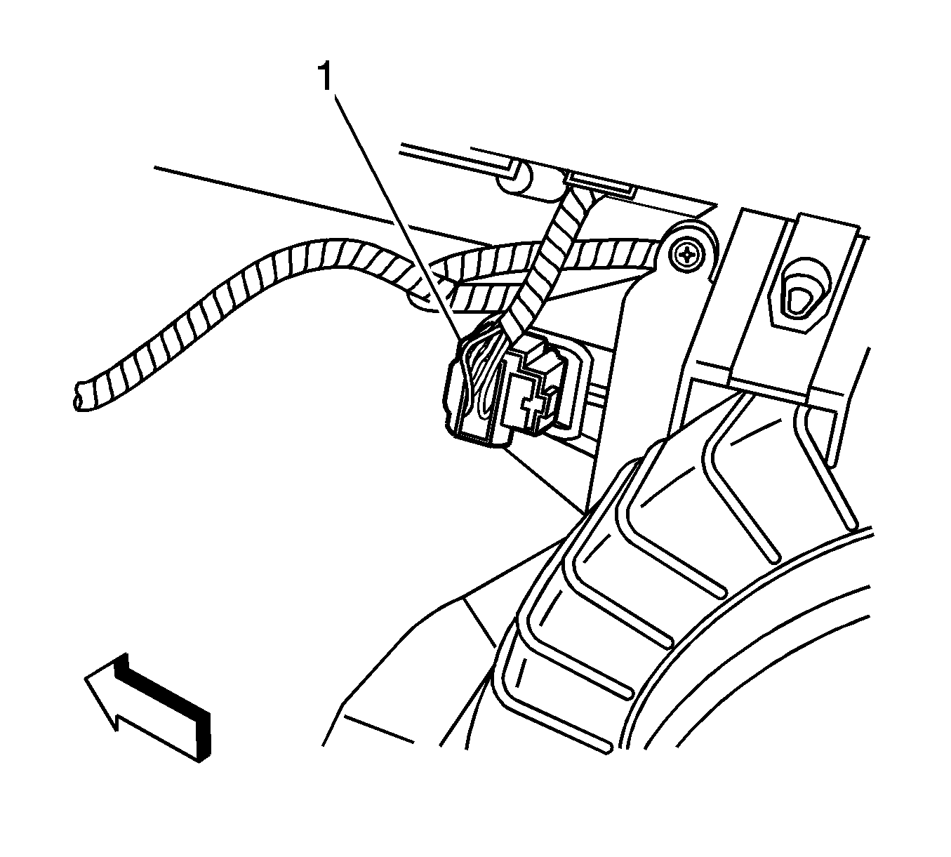
- Disconnect the air inlet assembly electrical connector (1).
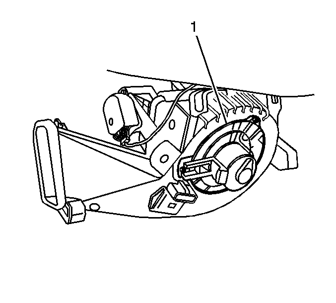
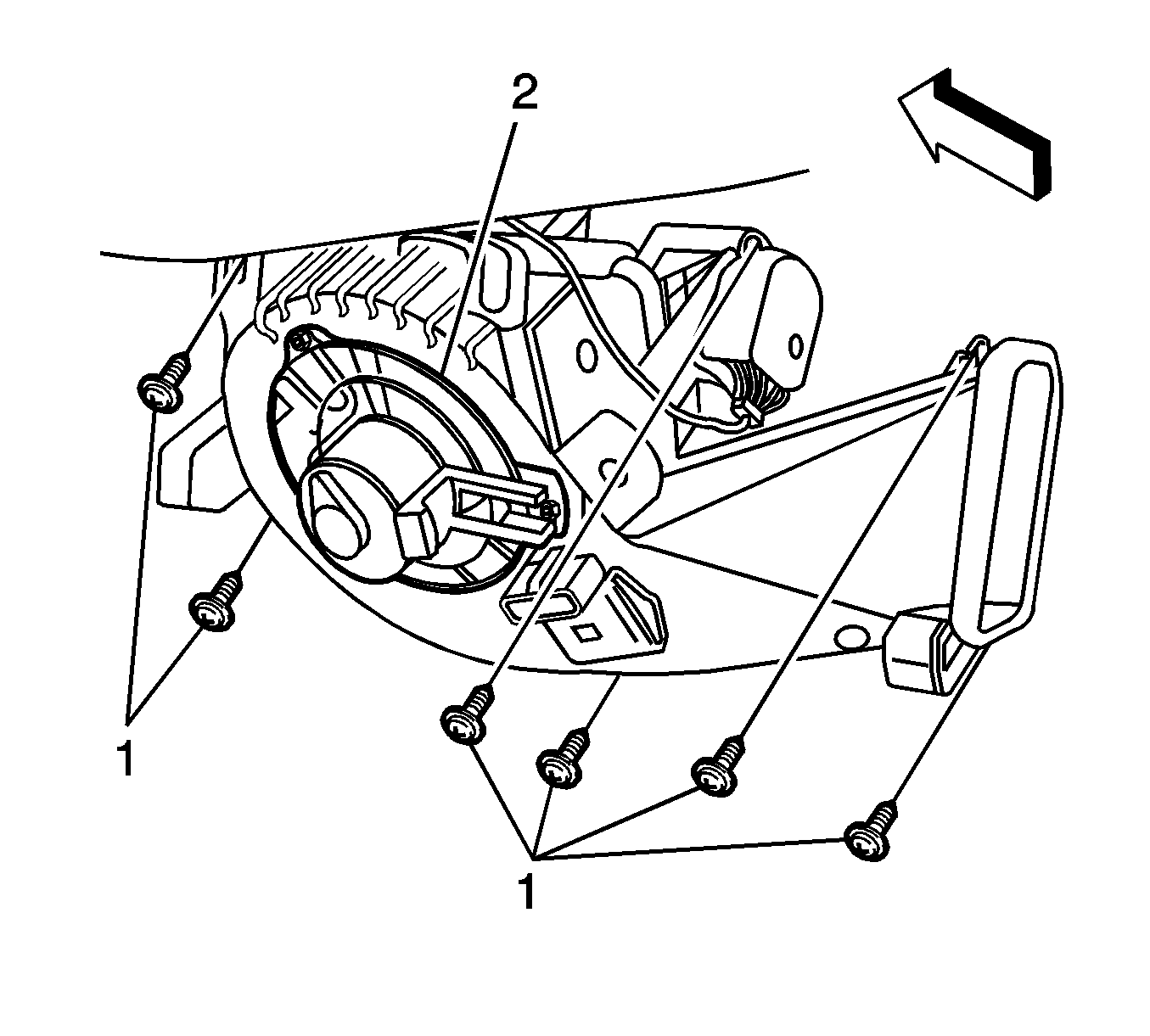
- Rotate the air inlet assembly (1) and remove.
Installation Procedure
- Connect the air inlet assembly electrical connector (1).
- Install the air inlet assembly (1) to the locator pin.
- Install the upper air inlet assembly bolts (1).
- Install the lower right air inlet assembly bolt (1).
- Install the I/P compartment. Refer to Instrument Panel Compartment Replacement .
- Install the closeout panel. Refer to Instrument Panel Insulator Panel Replacement - Right Side .


Notice: Refer to Fastener Notice in the Preface section.

Tighten
Tighten the bolt to 9 N·m (80 lb in).

Tighten
Tighten the bolt to 9 N·m (80 lb in).
Air Inlet Assembly Replacement Right Hand Drive
Removal Procedure
- Remove the instrument panel (I/P) compartment. Refer to Instrument Panel Compartment Replacement .
- Remove the left insulator panel. Refer to Instrument Panel Insulator Panel Replacement - Left Side .
- Remove the upper air inlet assembly bolts (1) from the I/P carrier.
- Remove the lower left air inlet assembly bolt from I/P carrier (1).
- Slide the assembly to the left and then lower.
- Disconnect the air inlet assembly electrical connector (1).
- Rotate the air inlet assembly (1) and remove.
Installation Procedure
- Install the air inlet assembly (1) to the locator pin.
- Connect the air inlet assembly electrical connector (1).
- Install the upper air inlet assembly bolts to I/P carrier (1).
- Install the lower right air inlet assembly bolt to I/P carrier (1).
- Install the I/P compartment. Refer to Instrument Panel Compartment Replacement .
- Install the left insulator panel. Refer to Instrument Panel Insulator Panel Replacement - Left Side .


Notice: Refer to Fastener Notice in the Preface section.

Tighten
Tighten the bolt to 9 N·m (80 lb in).

Tighten
Tighten the bolt to 9 N·m (80 lb in).
