For 1990-2009 cars only
Tools Required
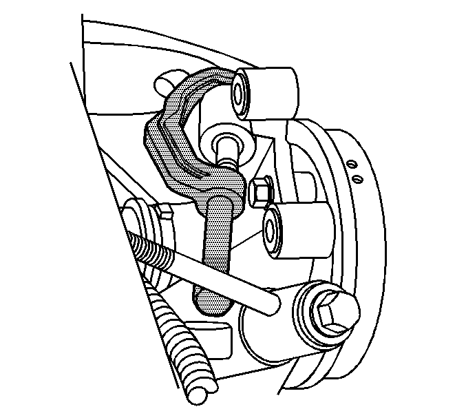
J 43631 Ball Joint Remover
Removal Procedure
- Raise and support the vehicle. Refer to Lifting and Jacking the Vehicle .
- Remove the tire and wheel. Refer to Tire and Wheel Removal and Installation .
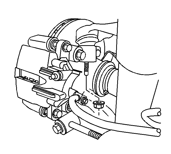
- Remove the upper control arm to knuckle retaining nut.
- Using the J 43631 , disconnect the upper control arm from the knuckle.
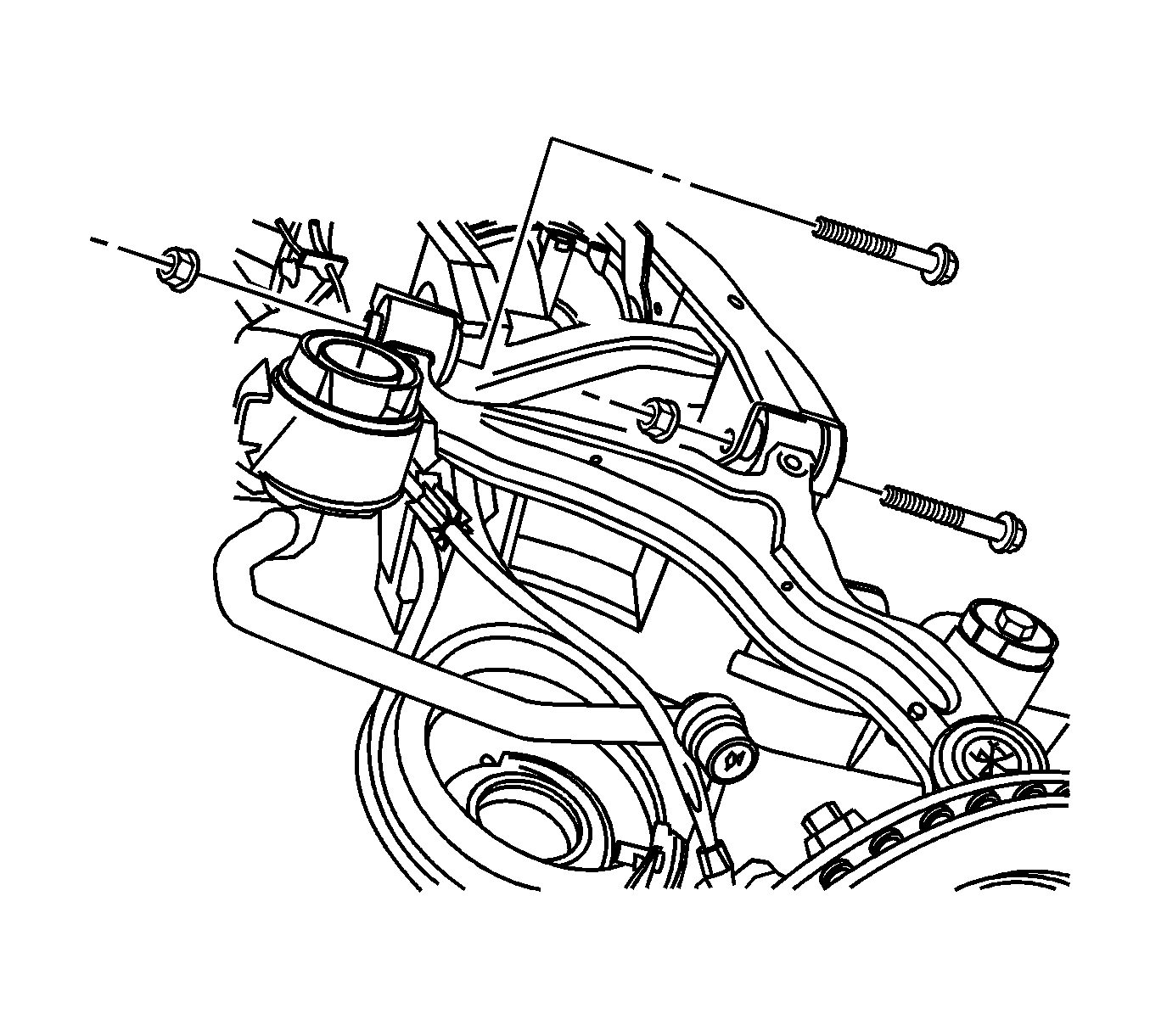
- Remove the upper control arm to frame mounting nuts and discard.
- Remove the upper control arm to frame mounting bolts and discard.
- Remove the upper control arm from the vehicle.
Notice: The ball stud must not rotate during disassembly or reassembly. Hand tools must be used to keep the ball stud from rotating. If air tools are used and the stud is allowed to rotate, damage to the ball stud and/or stud mounting hole may occur.


Notice: Do not free the ball stud by using a pickle fork or a wedge-type tool. Damage to the seal or bushing may result.

Installation Procedure
- Install the upper control arm to the vehicle.
- Install the upper control arm to frame mounting bolts.
- Install the upper control arm to frame mounting nuts.
- Install the upper control arm to the knuckle.
- Install the upper control arm to knuckle retaining nut.
- Install the tire and wheel. Refer to Tire and Wheel Removal and Installation .
- Lower the vehicle.

Important: Loosely install all fasteners before tightening.
Notice: Refer to Fastener Notice in the Preface section.
Tighten
| • | Tighten the upper control arm to knuckle nut to 20 N·m (15 lb ft) plus an additional 210 degrees. |
| • | Tighten new upper control arm to frame bolts to 120 N·m (89 lb ft). |
| • | Tighten new upper control arm to frame nuts to 120 N·m (89 lb ft). |
