For 1990-2009 cars only
Removal Procedure
- Raise and support the vehicle. Refer to Lifting and Jacking the Vehicle.
- Remove the tire and wheel. Refer to Tire and Wheel Removal and Installation.
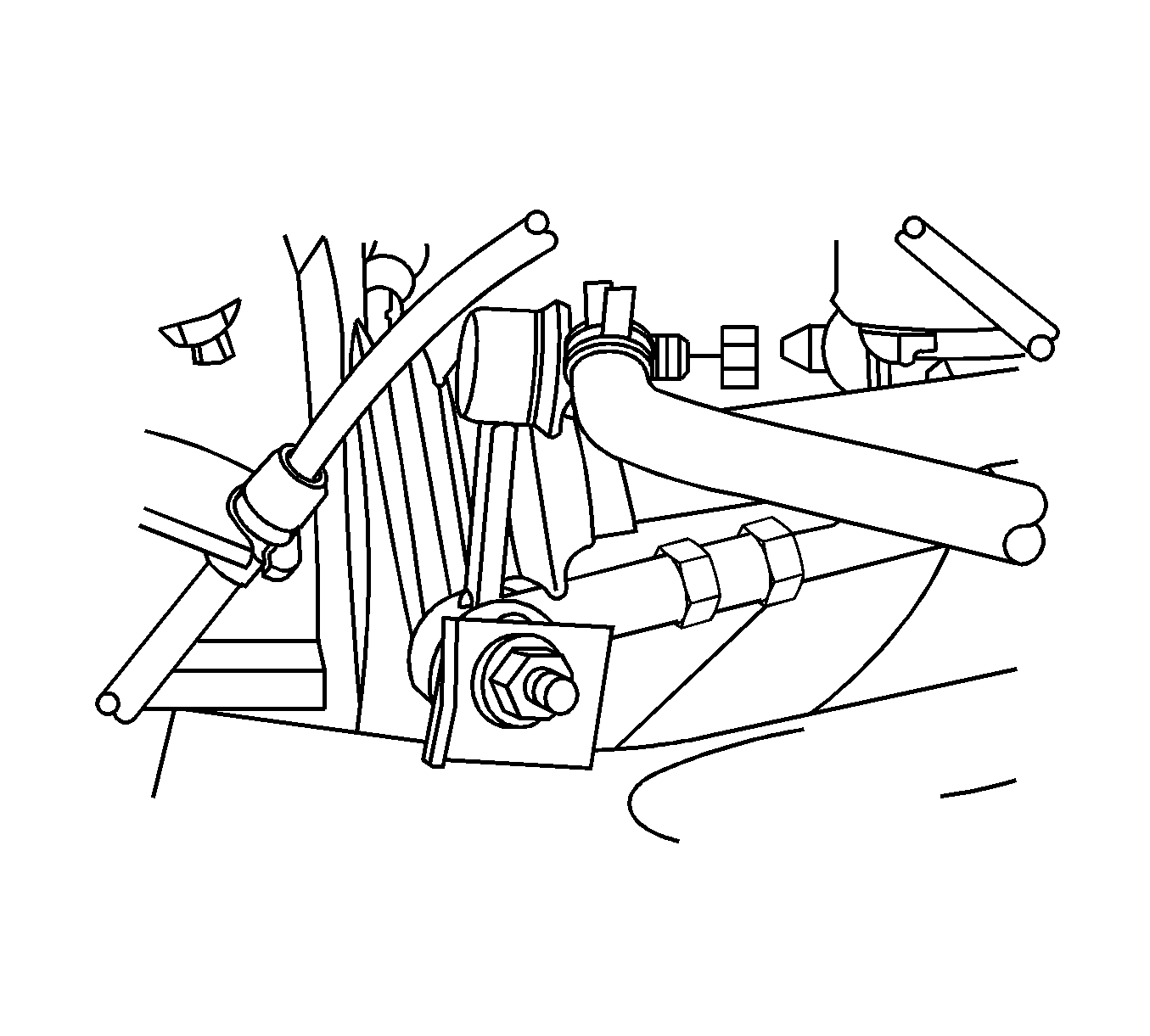
- Remove the stabilizer shaft link retaining nuts.
- Remove the stabilizer shaft link from the stabilizer shaft.
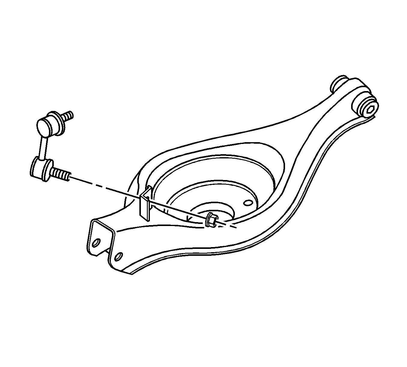
- Remove the stabilizer shaft link from the lower control arm.

Notice: The ball stud must not rotate during disassembly or reassembly. Hand tools must be used to keep the ball stud from rotating. If air tools are used and the stud is allowed to rotate, damage to the ball stud and/or stud mounting hole may occur.
Important: Hold the shaft link stud with a hex tool to prevent damage to the link seal.

Installation Procedure
- Install the stabilizer shaft link to the lower control arm.
- Install the stabilizer shaft link to the stabilizer shaft.
- Install the stabilizer shaft link retaining nuts.
- Install the tire and wheel. Refer to Tire and Wheel Removal and Installation.
- Lower the vehicle.


Notice: Refer to Fastener Notice in the Preface section.
Important: Hold the shaft link stud with a hex tool to prevent damage to the link seal.
Tighten
Tighten the nuts to 66 N·m (49 lb ft).
