Hard Brake Pedal on Cold Start at High Altitudes (Install Auxiliary Vacuum Pump)

| Subject: | Hard Brake Pedal on Cold Start at High Altitudes (Install Auxiliary Vacuum Pump) |
| Models: | 2008 Cadillac SRX |
| with 3.6L Engine (VIN 7 -- RPO LY7) |
Condition
Some customers may comment on a hard brake pedal. This condition is most apparent in the first 30 seconds to 1 minute after a cold start and at high altitudes, usually between 1219-1829 m (4,000-6,000 ft).
Cause
This condition may be caused by low engine vacuum during warm up.
Correction
Install an auxiliary vacuum pump, P/N 89058946 with installation kit, P/N 25927642, using the procedure below.
- Remove the three TORX® head bolts and rotate the pump assembly clockwise one bolt position. Apply GM Threadlocker Medium Strength Blue, P/N 12345382 (in Canada, P/N 10953489) or equivalent, to the three TORX® head bolts and tighten.
- Remove the two rubber isolation pads from the pump and discard them.
- Install the electrical wiring harness to the pump.
- Install the bracket to the lower arm of the pump.
- Hand tighten the bolt and nut.
- Disconnect the negative battery cable.
- Remove the cross vehicle brace.
- Remove the engine cover.
- Install a 6 mm nut onto the 6 mm stud located under the cross brace on the right strut tower. Run the nut all the way down until it makes contact with the tower.
- Remove and discard the brake booster vacuum hose. Leave the check valve connected to the booster.
- Install the vacuum pump on the right strut tower. Install the 6 mm nut onto the stud as seen in the illustration above.
- Rotate the pump so that the bracket slides onto the strut module mounting stud.
- Tighten the nut and bolt on the bracket for the vacuum pump.
- Install the 12 mm nut onto the strut module mounting stud and tighten.
- Tighten the 6 mm nut on the stud.
- Cut a piece of 12 mm (15/32") ID reinforced EPDM rubber vacuum hose 1250 mm (49 1/4") long. Install a hose clamp on each end of the hose.
- Install the hose to the vacuum pump outlet port (THE PORT FACING DOWN). Move the hose clamp into position to secure the hose to the pump.
- Route the hose behind the engine and connect it to the vacuum port on the engine and install the hose clamp.
- Cut a piece of 12 mm (15/32") ID reinforced EPDM rubber vacuum hose 990 mm (39") long and install a hose clamp on each end.
- Install the hose to the inlet port of the vacuum pump that faces the engine. Route the hose behind the engine and connect it to the brake booster valve.
- Secure each end of the hose with the clamps.
- Install a tie strap around the hoses and the battery ground cable.
- Install a tie strap around the hoses and the wiring harness in the back of the engine as seen in the illustration.
- Install the engine cover.
- Install the cross vehicle brace.
- Route the vacuum pump harness around the strut tower and secure the ground strap to the ground on the strut tower.
- Remove the cover from the underhood bussed electrical center (UHBEC).
- Remove the positive battery cable from the electrical center.
- Loosen the retaining bolts in the electrical center.
- Loosen the retaining clips on the sides of the electrical center and remove.
- Remove the electrical connector as seen in the illustration above.
- Splice into the ABS ignition feed circuit 2039 (J 134 cavity 39).
- Strip back 1 to 2 inches of insulation on the feed wire for the vacuum pump.
- Center strip the insulation on the existing circuit and pull back the insulation in both directions.
- Wrap the new wire around the existing circuit and solder the splice.
- Pull the new wire along the side of the existing circuit and wrap it with 3M Electrical Moisture Sealant Tape.
- Install the electrical connectors to the underhood electrical center.
- Install the underhood bussed electrical center and tighten the fastener.
- Install the cover.
- Remove the 10 amp fuse for the ABS ignition feed circuit and replace it with a 15 amp fuse.
- Install the cover.
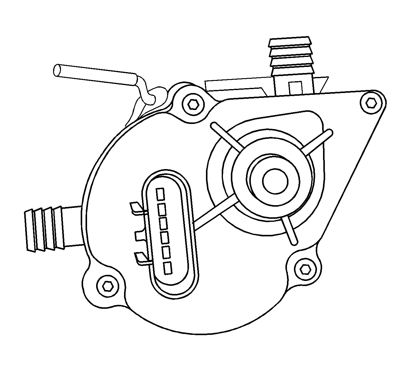
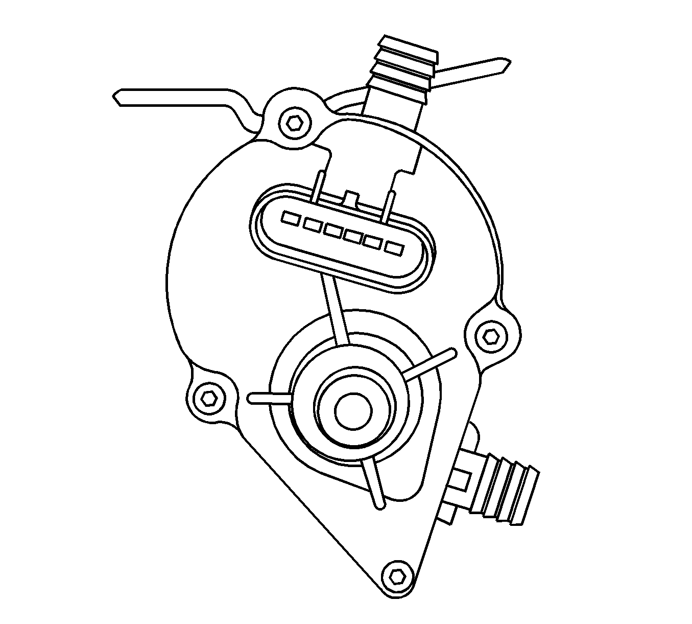
Tighten
Tighten the three TORX® head bolts to 1.36 N·m (12 lb in).
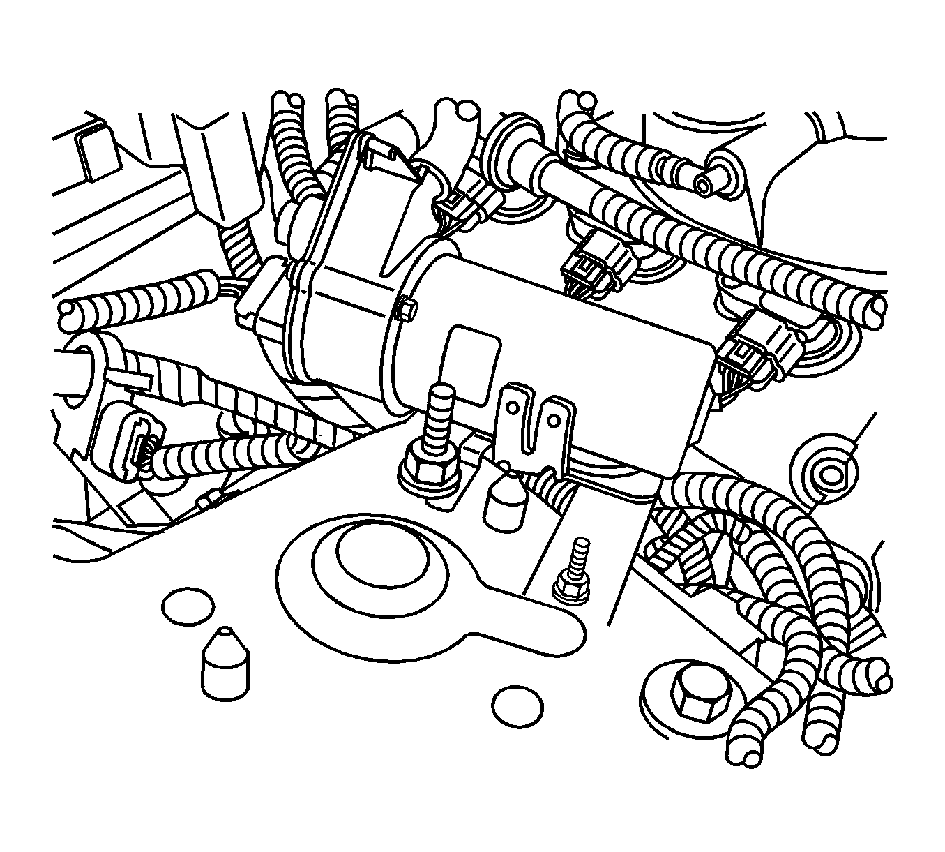
Tighten
tighten the nut and bolt to 9 N·m (80 lb in).
Tighten
Tighten the nut to 50 N·m (37 lb ft).
Tighten
Tighten the nut to 9 N·m (80 lb in).
Important: Be careful not to kink the hose.
Tighten
tighten the brace bolts to 25 N·m (18 lb ft).
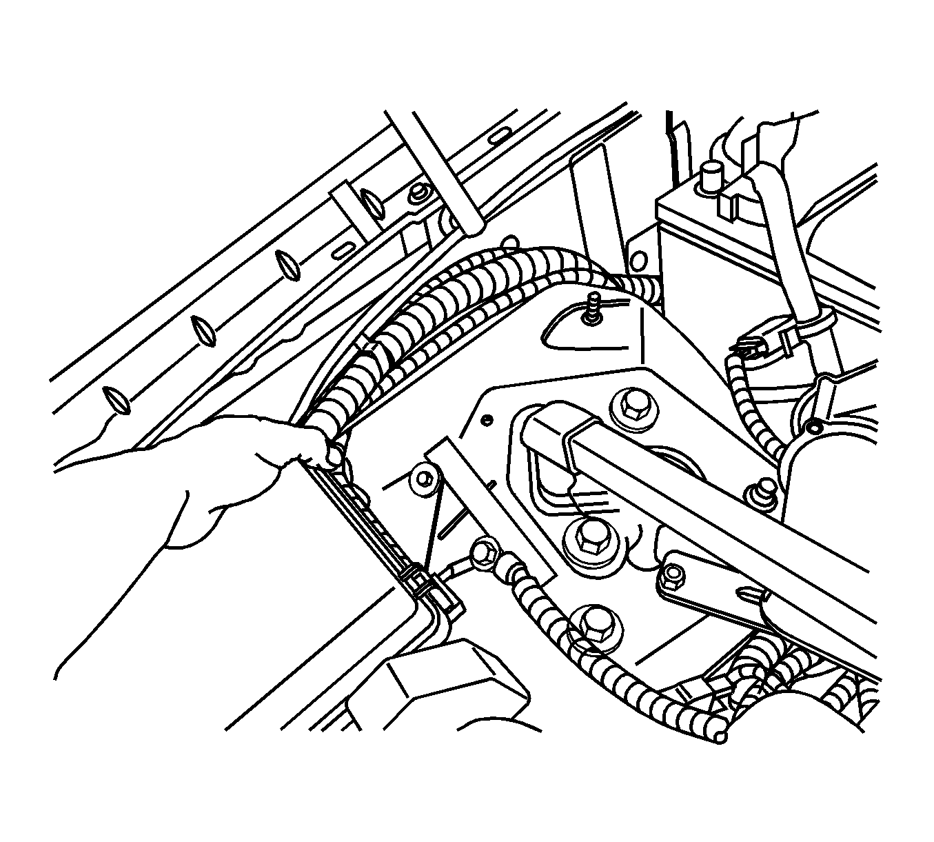
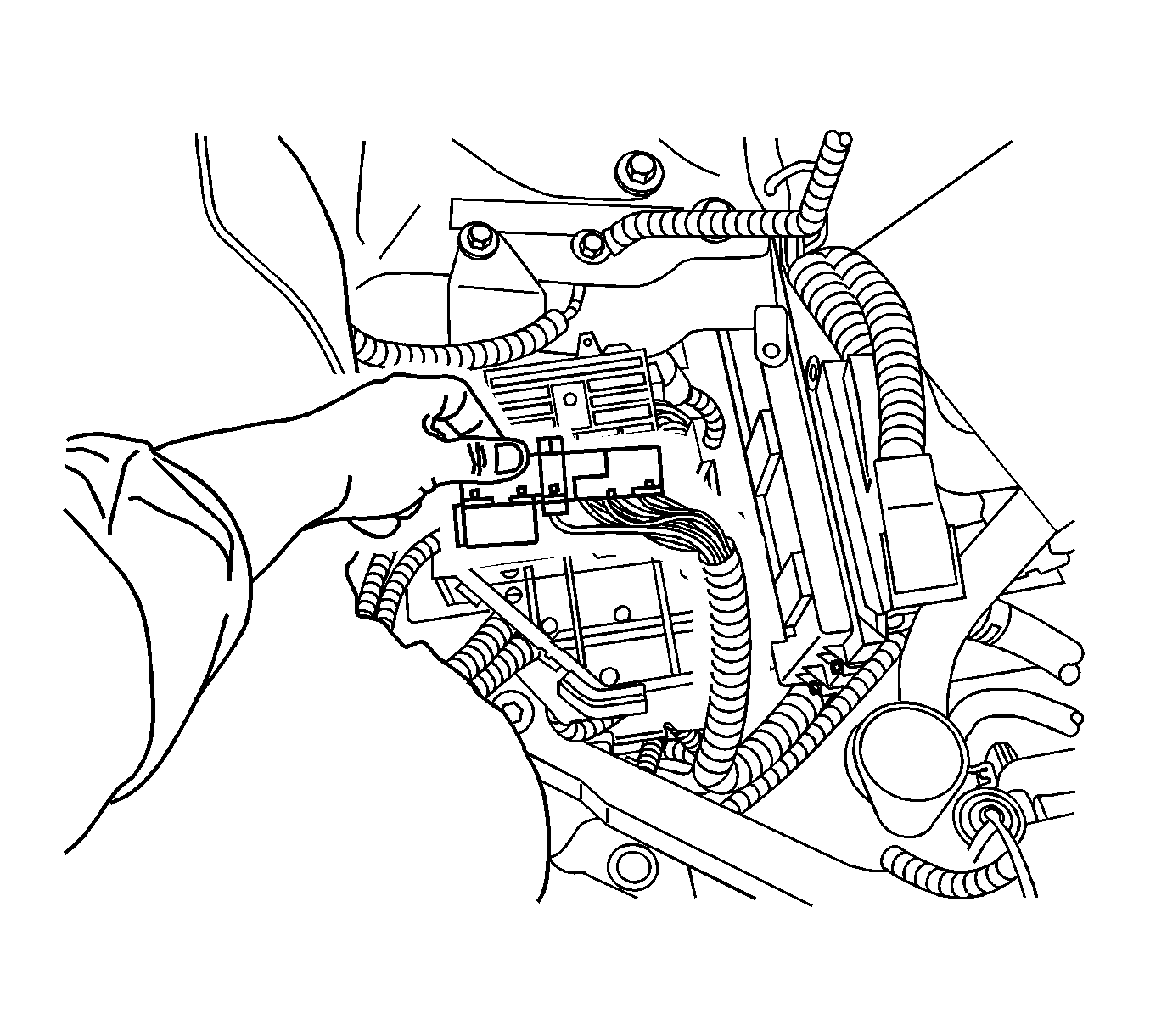
Tighten
Tighten the fastener to 7 N·m (62 lb in).
Purchase the following material locally.
| • | 3M Electrical Moisture Sealant Tape P/N 06149 |
| • | (15/32") or (1/2") ID reinforced EPDM rubber vacuum hose |
Parts Information
Part Number | Description | Qty |
|---|---|---|
25927642 | Vacuum Pump Kit | 1 |
89058946 | Vacuum Pump | 1 |
19116043 | Fuse | 1 |
12337820 | Tie Strap | 2 |
12345382 (in Canada, P/N 10953489) | Threadlocker Medium Strength-Blue | 1 |
Warranty Information
For vehicles repaired under warranty, use:
Labor Operation | Description | Labor Time |
|---|---|---|
H9716* | Install Power Brake Booster Pump Kit | 0.7 hr |
*This labor operation number is for bulletin use only. This number will not be published in the Labor Time Guide. | ||
