Hard Brake Pedal on Cold Start at High Altitudes (Install Auxiliary Vacuum Pump)

| Subject: | Hard Brake Pedal on Cold Start at High Altitudes (Install Auxiliary Vacuum Pump) |
| Models: | 2008-2009 Cadillac SRX |
| with 3.6L Engine (VIN 7 -- RPO LY7) |
This bulletin is being revised to add a model year and to include a diagnostic table. Please discard Corporate Bulletin Number 08-05-22-003 (Section 05 - Brakes).
Condition
Some customers may comment on a hard brake pedal. This condition is most apparent in the first 30 seconds to 1 minute after a cold start and at high altitudes, usually between 1219-1829 m (4,000-6,000 ft).
Cause
This condition may be caused by low engine vacuum during warm up.
Correction
Install an auxiliary vacuum pump, P/N 89058946 with installation kit, P/N 25927642, using the procedure below.
- Remove the three TORX® head bolts and rotate the pump assembly clockwise one bolt position. Apply GM Threadlocker Medium Strength Blue, P/N 12345382 (in Canada, P/N 10953489) or equivalent, to the three TORX® head bolts and tighten.
- Remove the two rubber isolation pads from the pump and discard them.
- Install the electrical wiring harness to the pump.
- Install the bracket to the lower arm of the pump.
- Hand tighten the bolt and nut.
- Disconnect the negative battery cable.
- Remove the cross vehicle brace.
- Remove the engine cover.
- Install a 6 mm nut onto the 6 mm stud located under the cross brace on the right strut tower. Run the nut all the way down until it makes contact with the tower.
- Remove and discard the brake booster vacuum hose. Leave the check valve connected to the booster.
- Install the vacuum pump on the right strut tower. Install the 6 mm nut onto the stud as seen in the illustration above.
- Rotate the pump so that the bracket slides onto the strut module mounting stud.
- Tighten the nut and bolt on the bracket for the vacuum pump.
- Install the 12 mm nut onto the strut module mounting stud and tighten.
- Tighten the 6 mm nut on the stud.
- Cut a piece of 12 mm (15/32") ID reinforced EPDM rubber vacuum hose 1250 mm (49 1/4") long. Install a hose clamp on each end of the hose.
- Install the hose to the vacuum pump outlet port (THE PORT FACING DOWN). Move the hose clamp into position to secure the hose to the pump.
- Route the hose behind the engine and connect it to the vacuum port on the engine and install the hose clamp.
- Cut a piece of 12 mm (15/32") ID reinforced EPDM rubber vacuum hose 990 mm (39") long and install a hose clamp on each end.
- Install the hose to the inlet port of the vacuum pump that faces the engine. Route the hose behind the engine and connect it to the brake booster valve.
- Secure each end of the hose with the clamps.
- Install a tie strap around the hoses and the battery ground cable.
- Install a tie strap around the hoses and the wiring harness in the back of the engine as seen in the illustration.
- Install the engine cover.
- Install the cross vehicle brace.
- Route the vacuum pump harness around the strut tower and secure the ground strap to the ground on the strut tower.
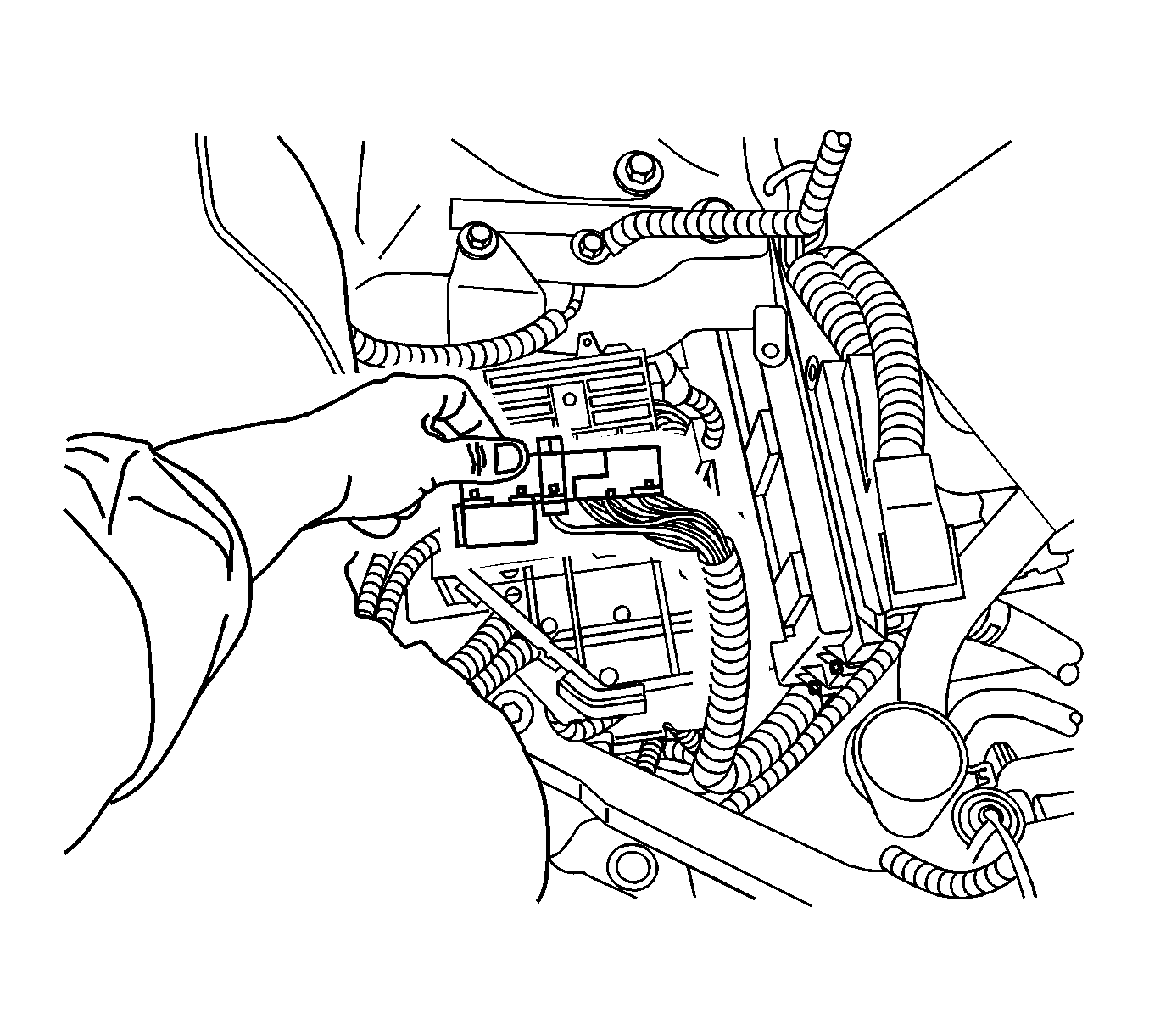
- Remove the cover from the underhood bussed electrical center (UHBEC).
- Remove the positive battery cable from the electrical center.
- Loosen the retaining bolts in the electrical center.
- Loosen the retaining clips on the sides of the electrical center and remove.
- Remove the electrical connector as seen in the illustration above.
- Splice into the ABS ignition feed circuit 2039 (J 134 cavity 39).
- Strip back 1 to 2 inches of insulation on the feed wire for the vacuum pump.
- Center strip the insulation on the existing circuit and pull back the insulation in both directions.
- Wrap the new wire around the existing circuit and solder the splice.
- Pull the new wire along the side of the existing circuit and wrap it with 3M Electrical Moisture Sealant Tape.
- Install the electrical connectors to the underhood electrical center.
- Install the underhood bussed electrical center and tighten the fastener.
- Install the cover.
- Remove the 10 amp fuse for the ABS ignition feed circuit and replace it with a 15 amp fuse.
- Install the cover.
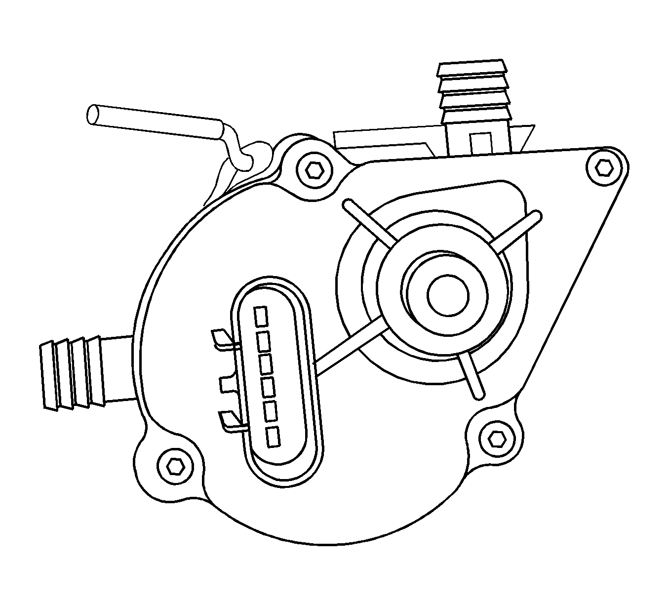
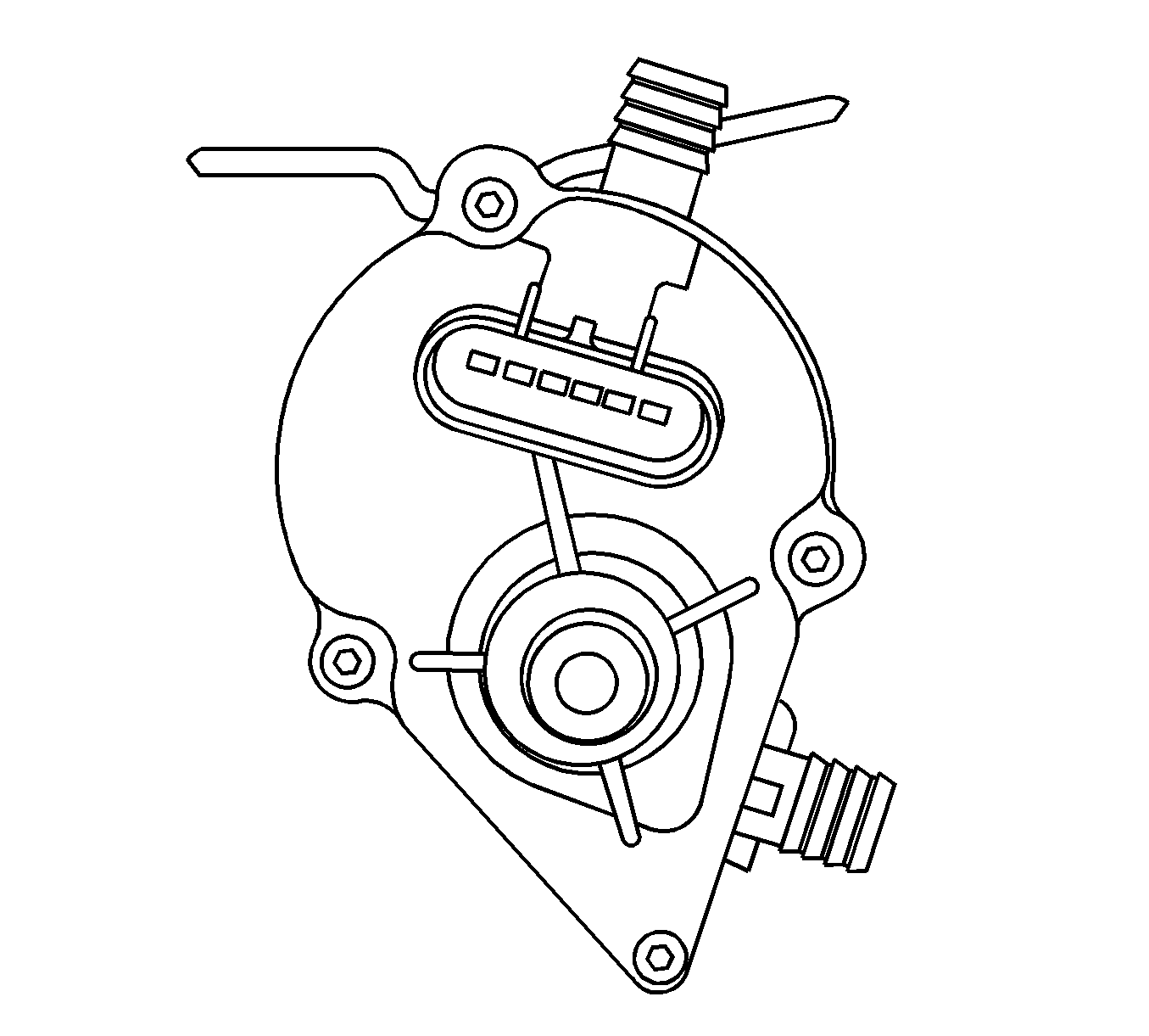
Tighten
Tighten the three TORX® head bolts to 1.36 N·m (12 lb in).
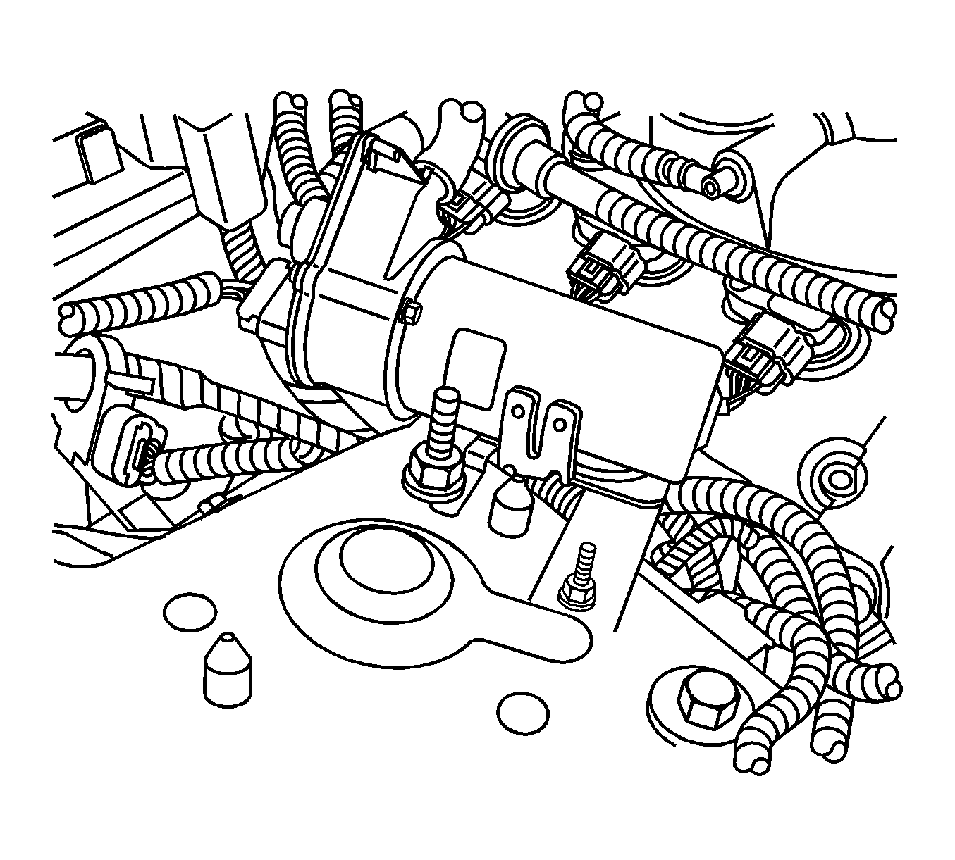
Tighten
tighten the nut and bolt to 9 N·m (80 lb in).
Tighten
Tighten the nut to 50 N·m (37 lb ft).
Tighten
Tighten the nut to 9 N·m (80 lb in).
Important: Be careful not to kink the hose.
Tighten
tighten the brace bolts to 25 N·m (18 lb ft).
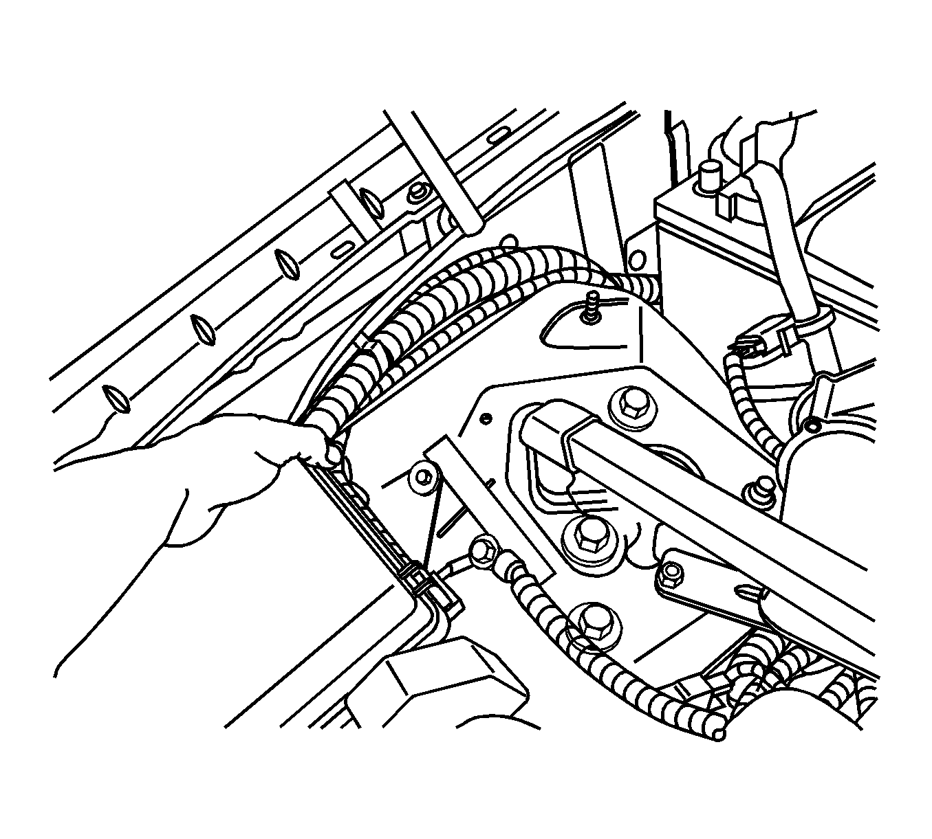
Tighten
Tighten the fastener to 7 N·m (62 lb in).
Purchase the following material locally.
| • | 3M Electrical Moisture Sealant Tape P/N 06149 |
| • | (15/32") or (1/2") ID reinforced EPDM rubber vacuum hose |
Inoperative Vacuum Pump
When power is supplied there is a 5 second delay until the pump works. The pump has it own vacuum sensor that turns the pump on and off. If the vacuum level drops below 6 inches of mercury the pump will turn on. Once it reaches 9 inches of mercury it will turn off. The pump can be check by removing the hose at the booter. Place you thumb over the hose and feel the vacuum pull down until it stops, release the vacuum and it should start again. If the pump runs continuous for 1 minute it will shut down until next key cycle to prevent overheating.
Step | Action | Yes | No |
|---|---|---|---|
1 | Does the pump run? | No action needed | Go to Step 2 |
2 | Check the 15 amp fuse in cavity 39. Is the fuse bad? | Go to Step 3 | Go to Step 4 |
3 | Check the B+ wire from the underhood electrical center for a short to ground. Was the concern repaired? | Go to Step 1 | Go to Step 4 |
4 | Check the B+ wire from the underhood electrical center for an open. Was the concern repaired? | Go to Step 1 | Go to Step 5 |
5 | Check the ground for an open. | Go to Step 1 | Go to Step 6 |
6 | Replace the vacuum pump. | Go to Step 1 |
|
Parts Information
Part Number | Description | Qty |
|---|---|---|
25927642 | Vacuum Pump Kit | 1 |
89058946 | Vacuum Pump | 1 |
19116043 | Fuse | 1 |
12337820 | Tie Strap | 2 |
12345382 (in Canada, P/N 10953489) | Threadlocker Medium Strength-Blue | 1 |
Warranty Information
For vehicles repaired under warranty, use:
Labor Operation | Description | Labor Time |
|---|---|---|
H9716* | Install Power Brake Booster Pump Kit | 0.7 hr |
*This is a unique labor operation for bulletin use only. It will not be published in the Labor Time Guide. | ||
