For 1990-2009 cars only
Special Tools
| • | EN 46328 Camshaft Holding Tool |
| • | J 39946 Crankshaft Socket |
Removal Procedure
- Remove the oil pump. Refer to Oil Pump Replacement.
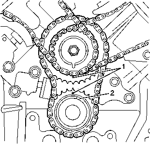
- Using the J 39946 , rotate the crankshaft until the primary timing gear marks (1) are adjacent to each other as shown.
- Remove the right camshaft position actuator housing. DO NOT remove the actuator solenoids from the housing. Refer to Camshaft Position Actuator Housing Replacement - Right Side.
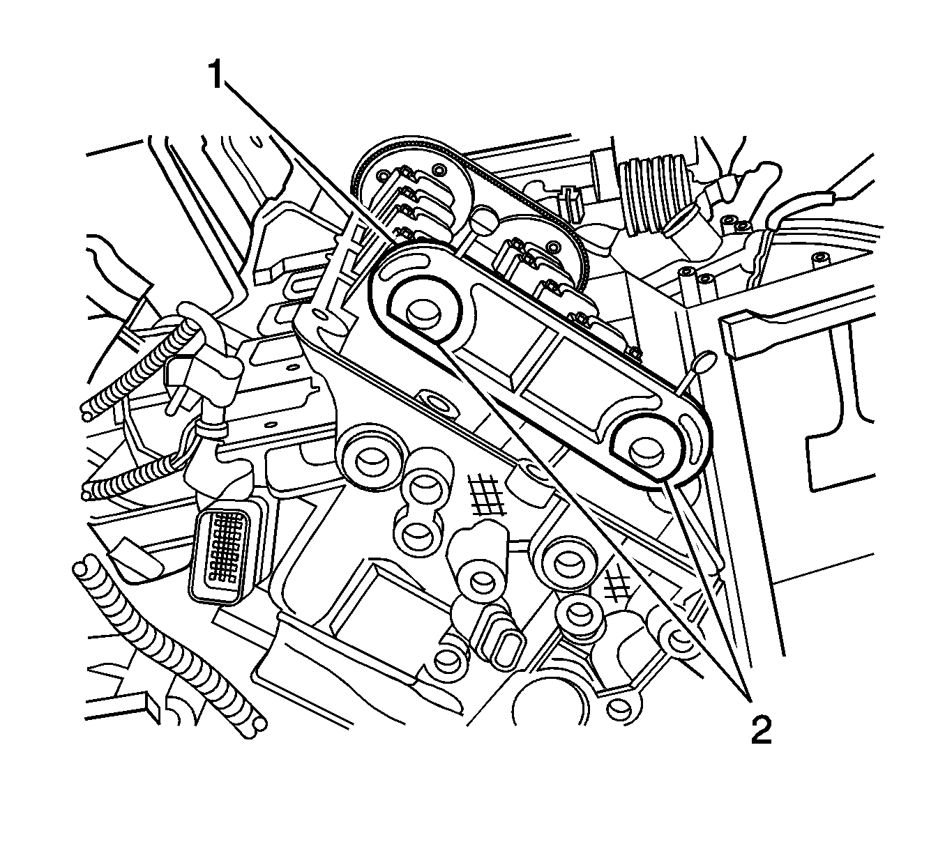
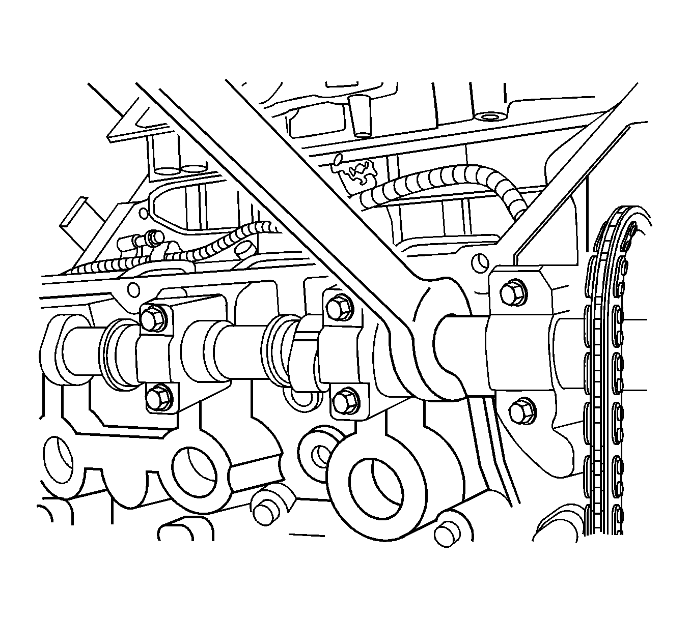
- Install the EN 46328 (1) on the bank 1 (right) camshafts (2).
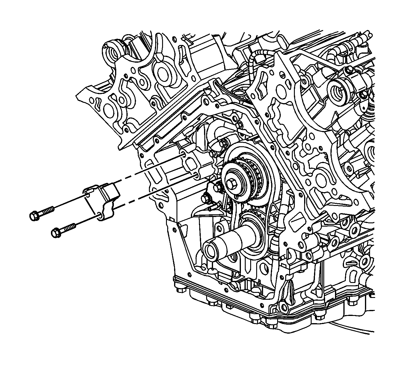
- Loosen and remove the right secondary timing chain tensioner bolts and tensioner. Refer to Secondary Camshaft Drive Chain Tensioner Replacement - Right Side.
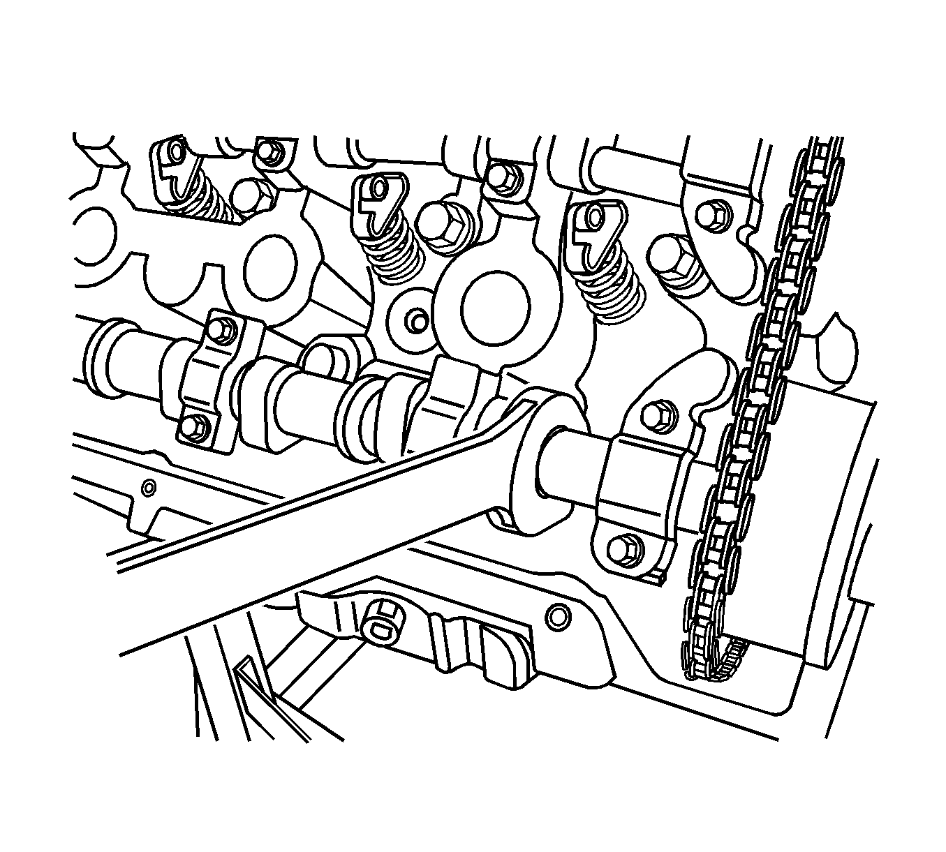
- Use an open-end wrench on the hex cast into the camshaft in order to prevent the camshaft from rotating when removing the camshaft oil control valve.
- Loosen and remove the bank 1 (right) exhaust camshaft position oil control valve.
- Slide the right exhaust camshaft position actuator off of the camshaft and remove the secondary timing chain from the camshaft actuator teeth.
- Use an open-end wrench on the hex cast into the camshaft in order to prevent the camshaft from rotating when removing the camshaft oil control valve.
- Loosen and remove the bank 1 (right) intake camshaft position oil control valve.
- Slide the right intake camshaft position actuator off of the camshaft and remove the secondary timing chain from the camshaft actuator teeth.
- Remove the right secondary timing chain from the engine.
- Clean and inspect the camshaft timing drive components. Refer to Camshaft Timing Drive Components Cleaning and Inspection.
Warning: Refer to Camshaft Holding Tool Warning in the Preface section.
Caution: Refer to Torque Reaction Against Timing Drive Chain Caution in the Preface section.
Caution: Refer to Torque Reaction Against Timing Drive Chain Caution in the Preface section.
Installation Procedure
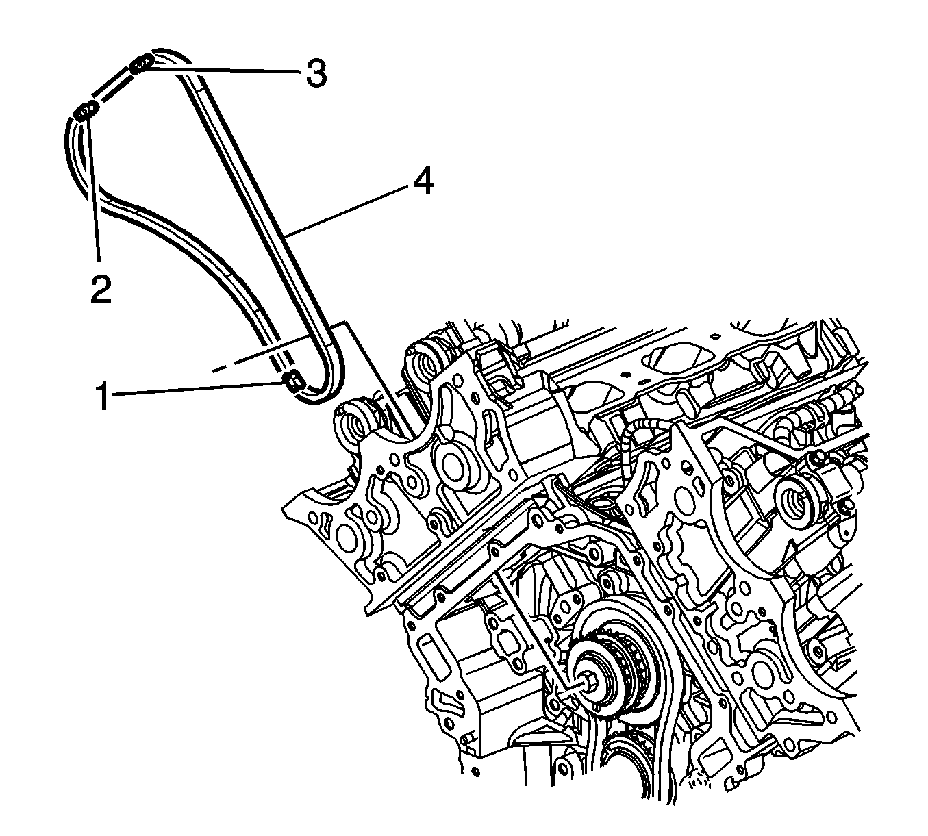
- The secondary timing chain has 3 black links that aid in timing the camshaft position actuators to the intermediate sprocket.
- The black link (2) is aligned with the bank 1 exhaust actuator timing mark. The black link (3) is aligned with the bank 1 intake actuator timing mark.
- The black link (1) is aligned with the intermediate sprocket.
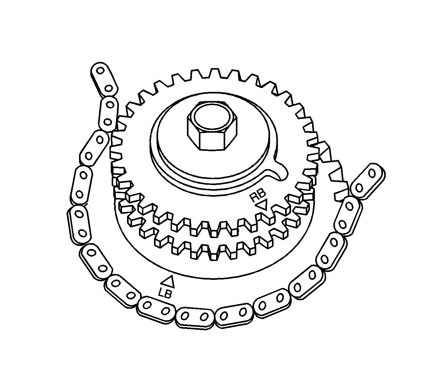
- The intermediate sprocket right bank timing mark is labeled right bank (RB) as shown.
- Assemble the secondary timing chain to the intermediate sprocket aligning the sprocket RB timing mark to the timing chain black link.
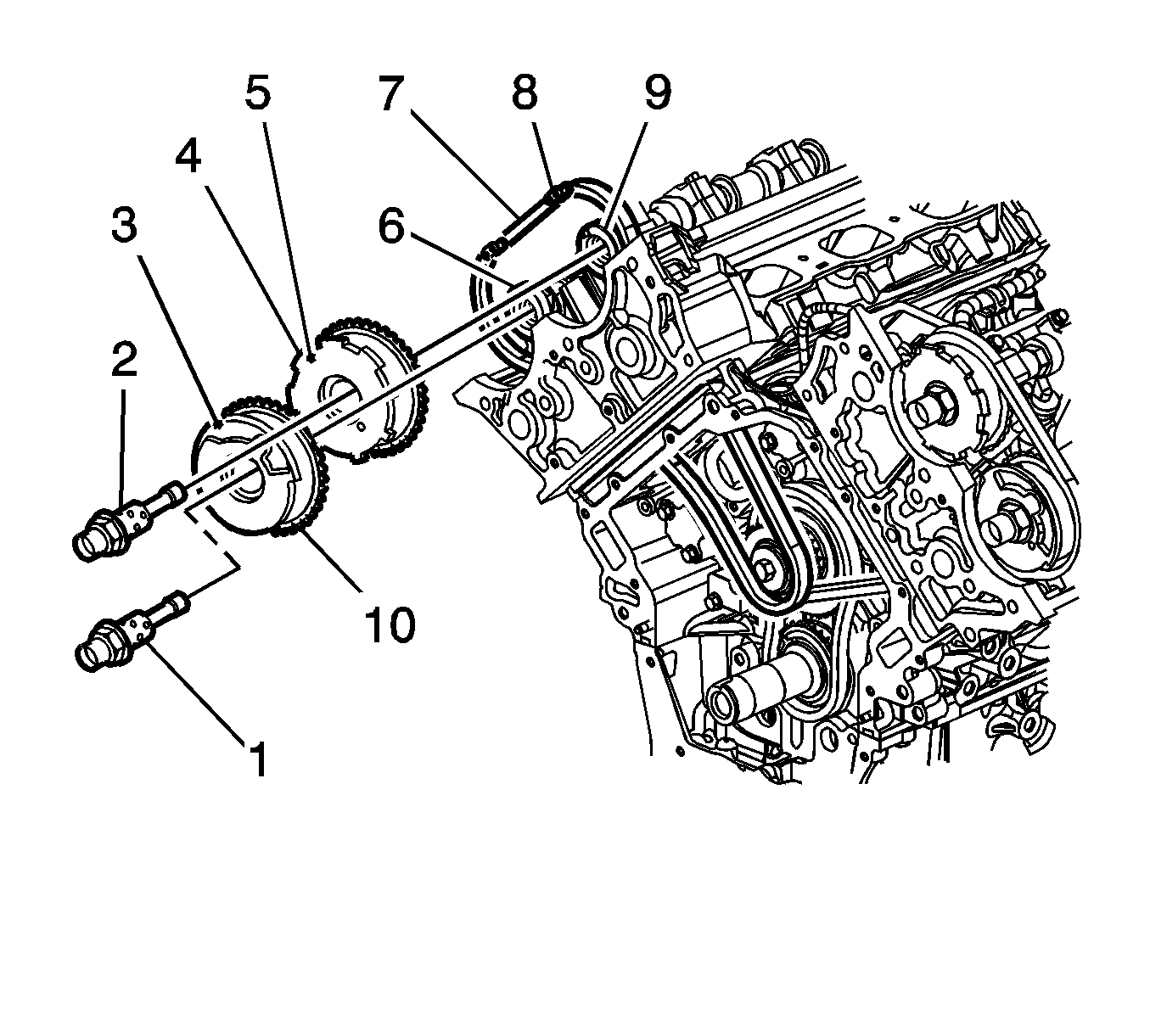
- Align the timing mark (5) of the RB intake camshaft position actuator with the timing chain black link (8) and install the actuator on the camshaft with the actuator timing mark perpendicular (90 degrees) to the cylinder head deck surface near the top of its rotation.
- Loosely install the oil control valve (2) to secure the intake actuator.
- Use an open-end wrench on the hex cast into the camshaft in order to prevent the camshaft from rotating when tightening the oil control valve to 120 N·m (89 lb ft).
- Align the timing mark (3) of the RB exhaust camshaft position actuator with the timing chain black link and install the actuator on the camshaft with the actuator timing mark perpendicular (90 degrees) to the cylinder head deck surface near the top of its rotation.
- Loosely install the oil control valve (1) to secure the exhaust actuator.
- Use an open-end wrench on the hex cast into the camshaft in order to prevent the camshaft from rotating when tightening the oil control valve to 120 N·m (89 lb ft).
- Install the right secondary timing chain tensioner. Refer to Secondary Camshaft Drive Chain Tensioner Replacement - Right Side.
- Remove the EN 46328 .
- Install the right camshaft position actuator housing. Refer to Camshaft Position Actuator Housing Replacement - Right Side.
- Install the oil pump. Refer to Oil Pump Replacement.
Caution: Refer to Torque Reaction Against Timing Drive Chain Caution in the Preface section.
Caution: Refer to Fastener Caution in the Preface section.

Caution: Refer to Torque Reaction Against Timing Drive Chain Caution in the Preface section.


