Brake Pedal Assembly Replacement RHD
Removal Procedure
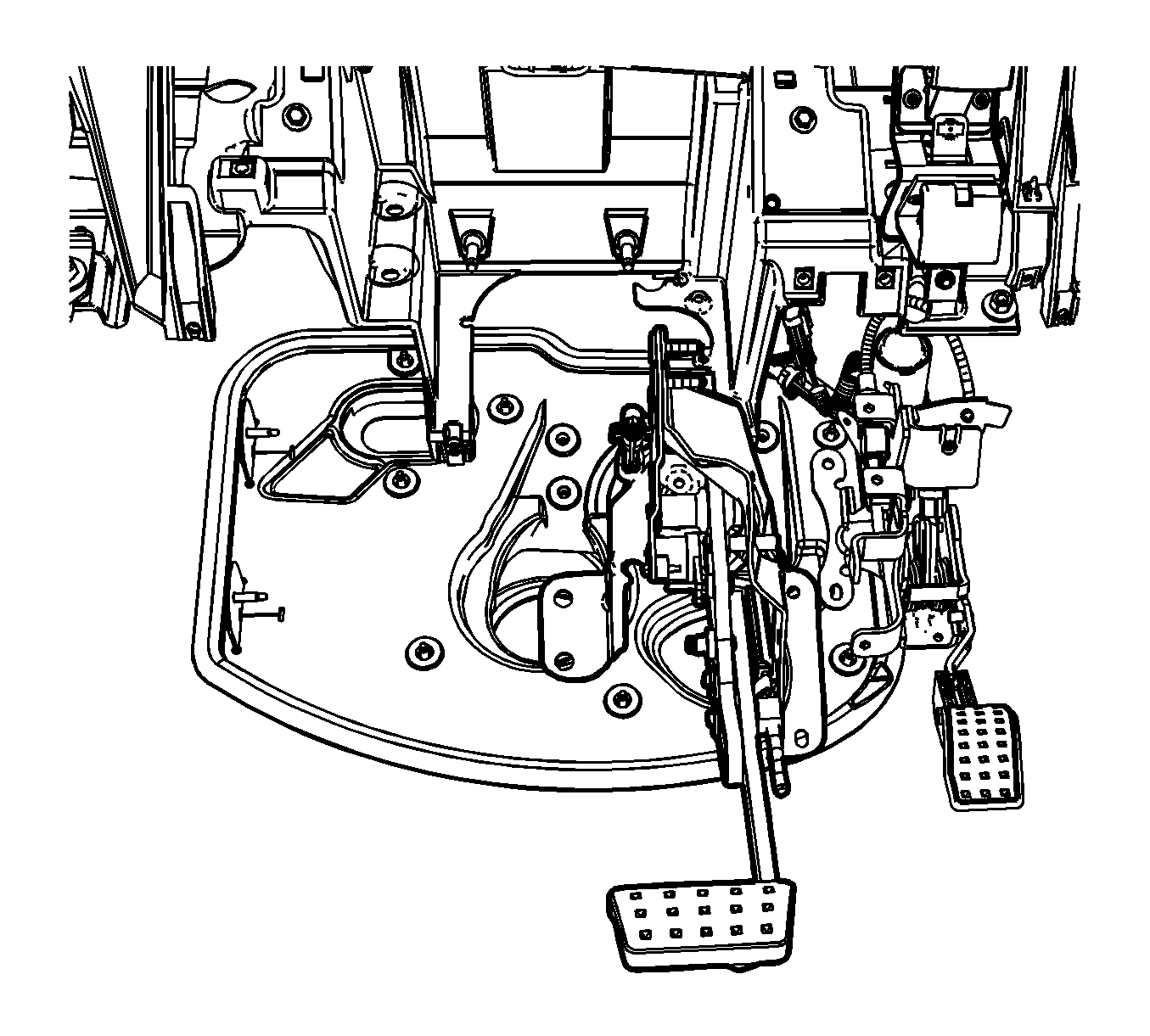
- Remove the vacuum brake booster. Refer to Power Vacuum Brake Booster Replacement.
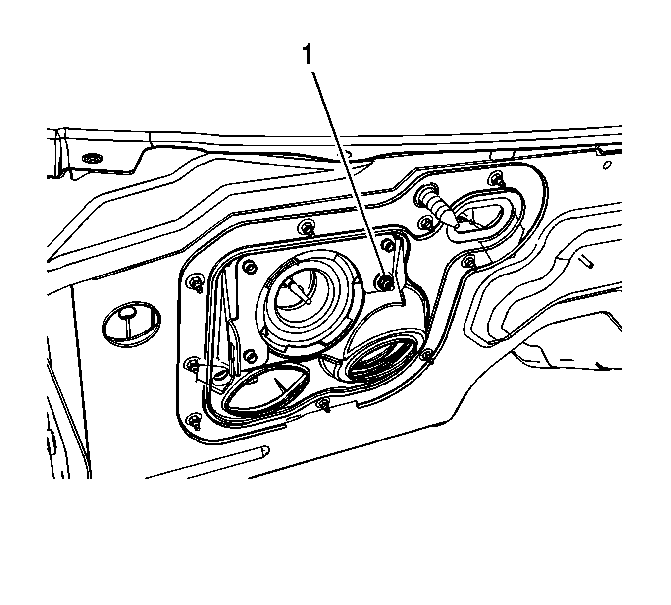
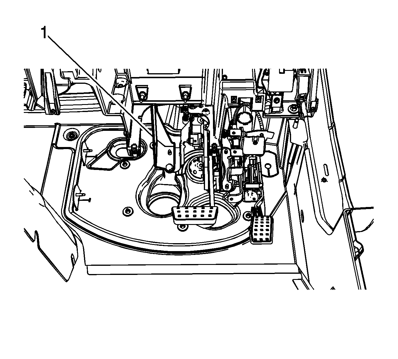
- Remove the vacuum brake booster mounting plate nut (1).
- Without disconnecting the steering column from the intermediate shaft, lower and support the steering column. Refer to Steering Column Replacement.
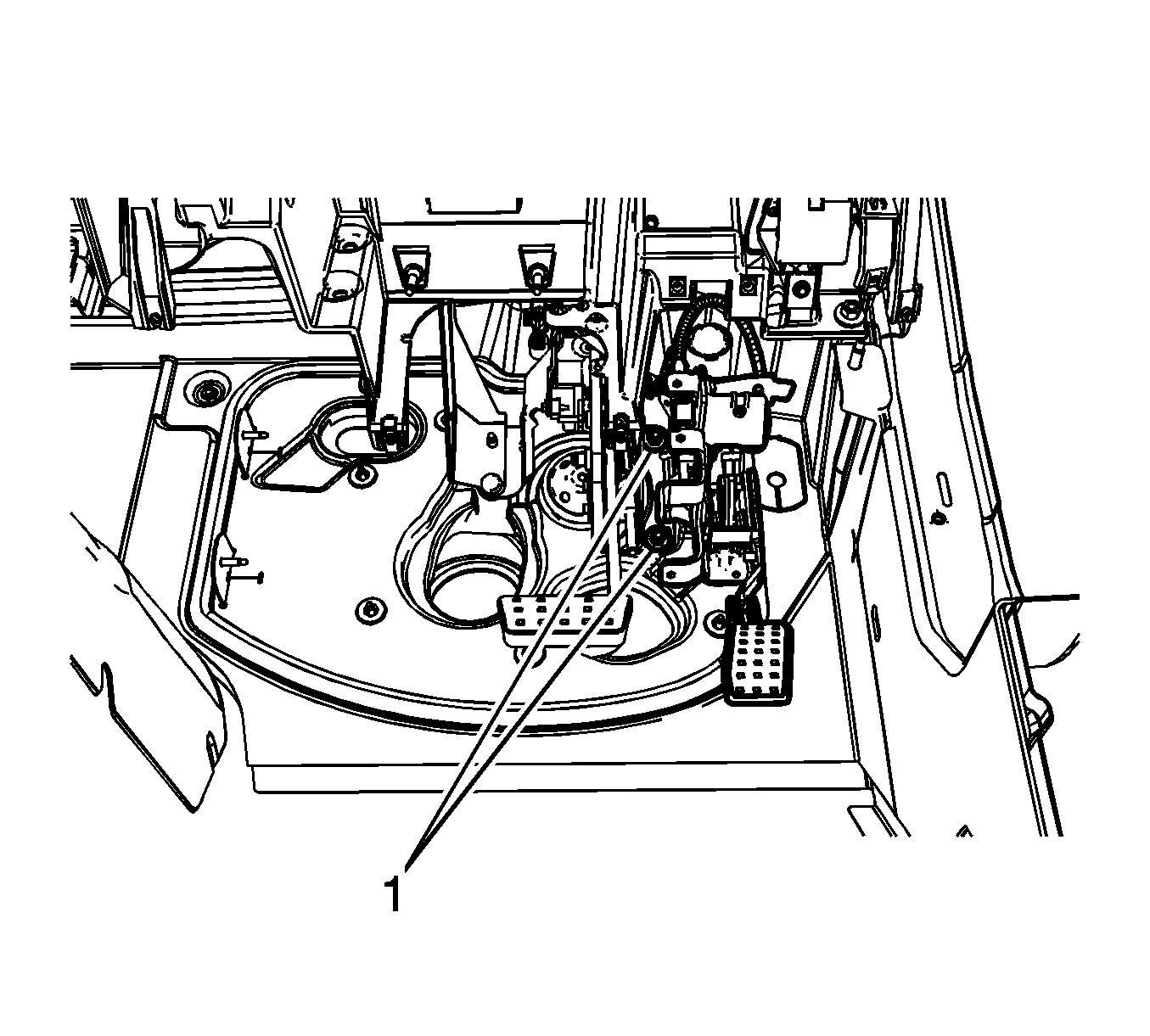
- Remove the 2 lower adjustable pedal assembly bracket nuts (1).
- Carefully lower the accelerator pedal and motor assembly to access the connectors.
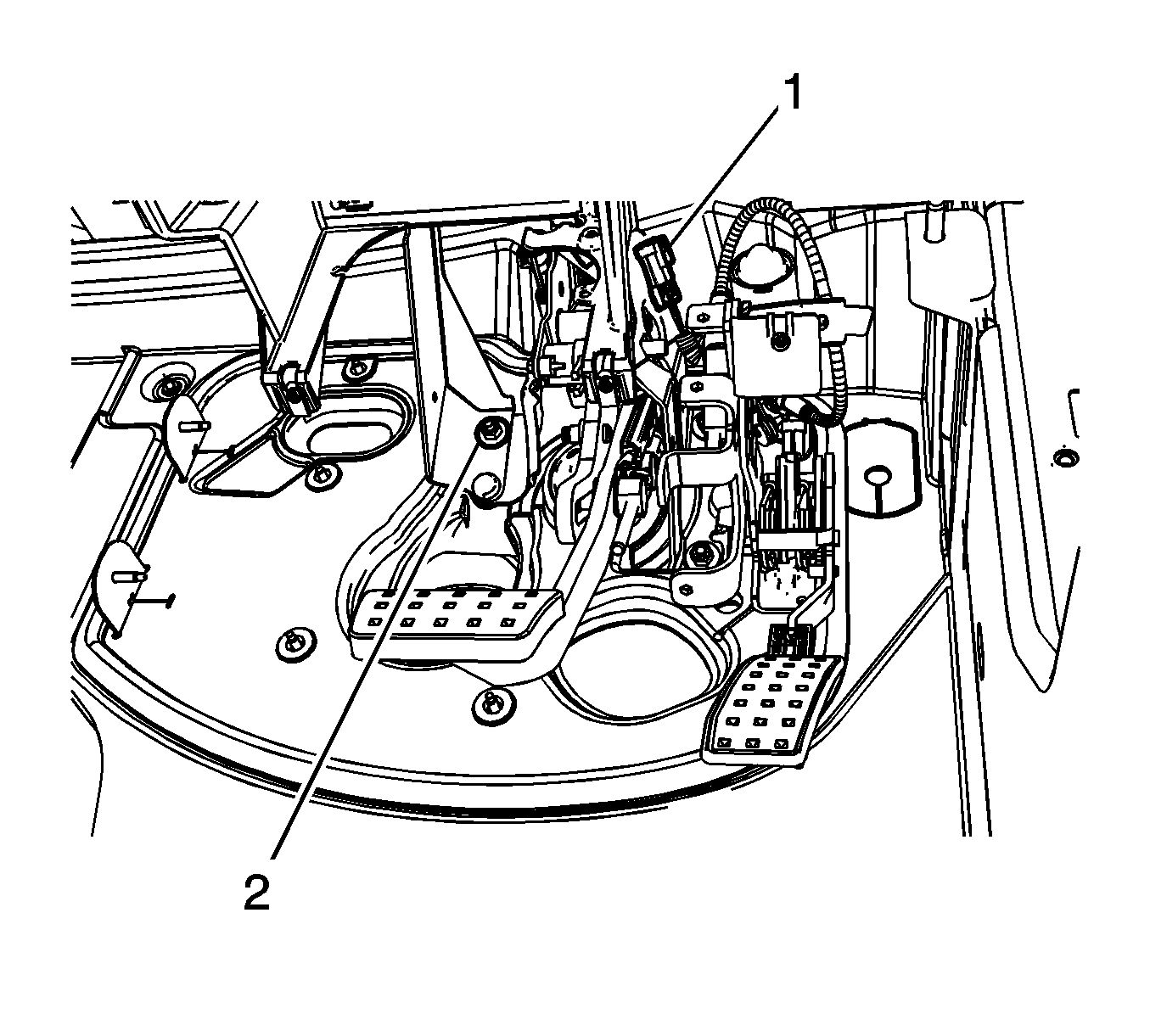
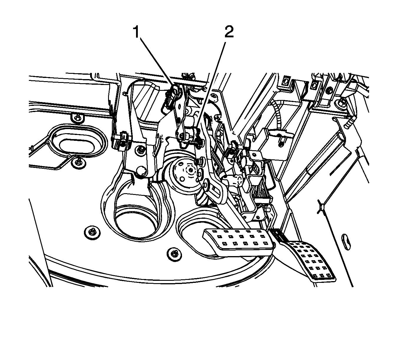
- Disconnect the accelerator pedal linear position sensor electrical connector (1) and release the clip from the brake pedal bracket.
- Remove the lower steering column support bracket nut (2).
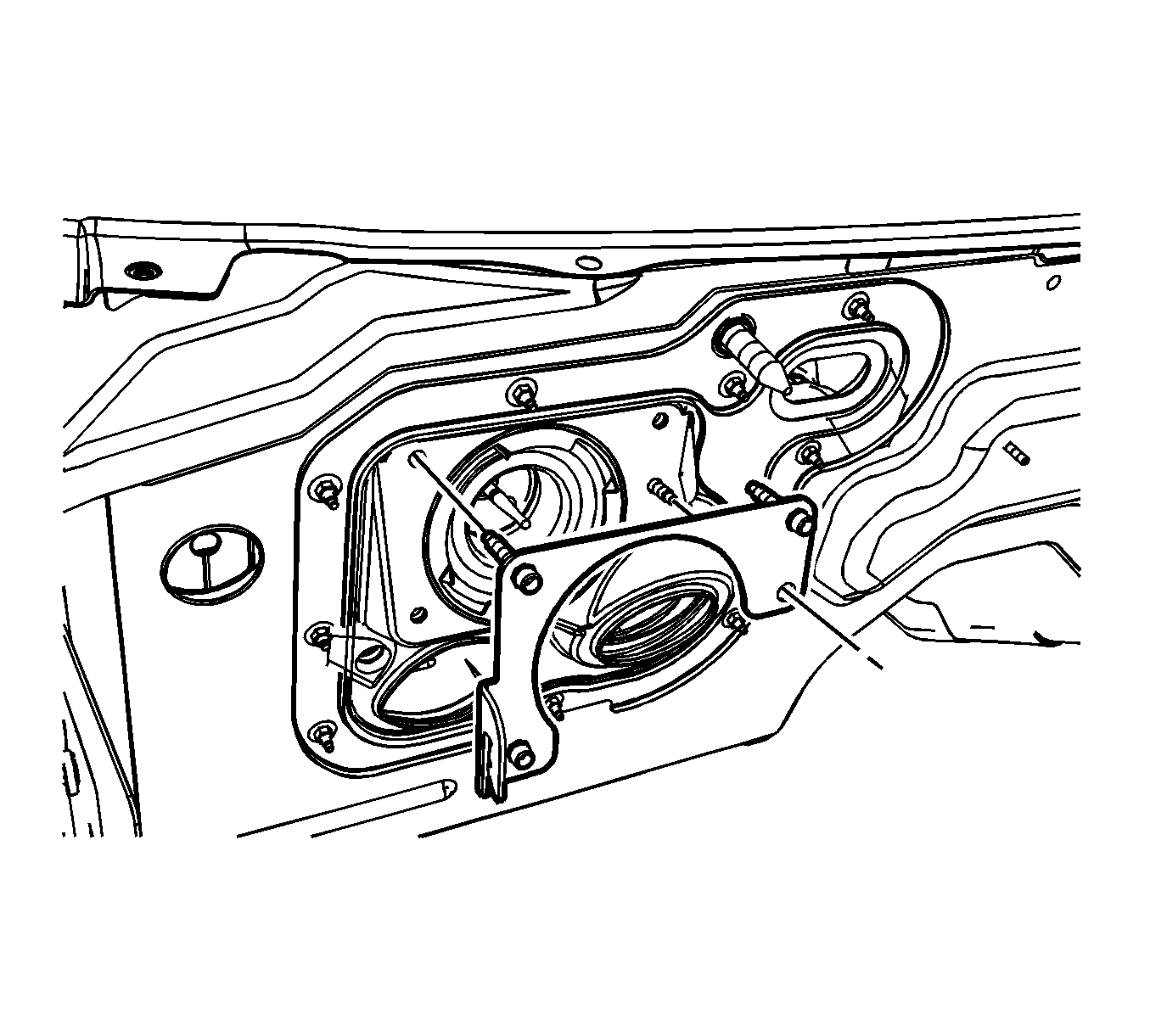
- Remove the vacuum brake booster mounting plate.
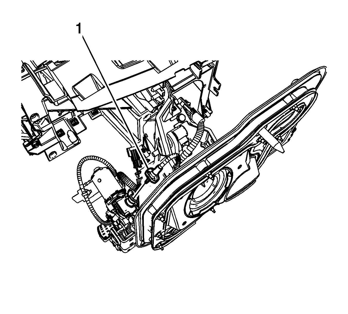
- Carefully compress the brake pedal adjuster actuator cable collar (1) at the motor and pull the cable straight out.
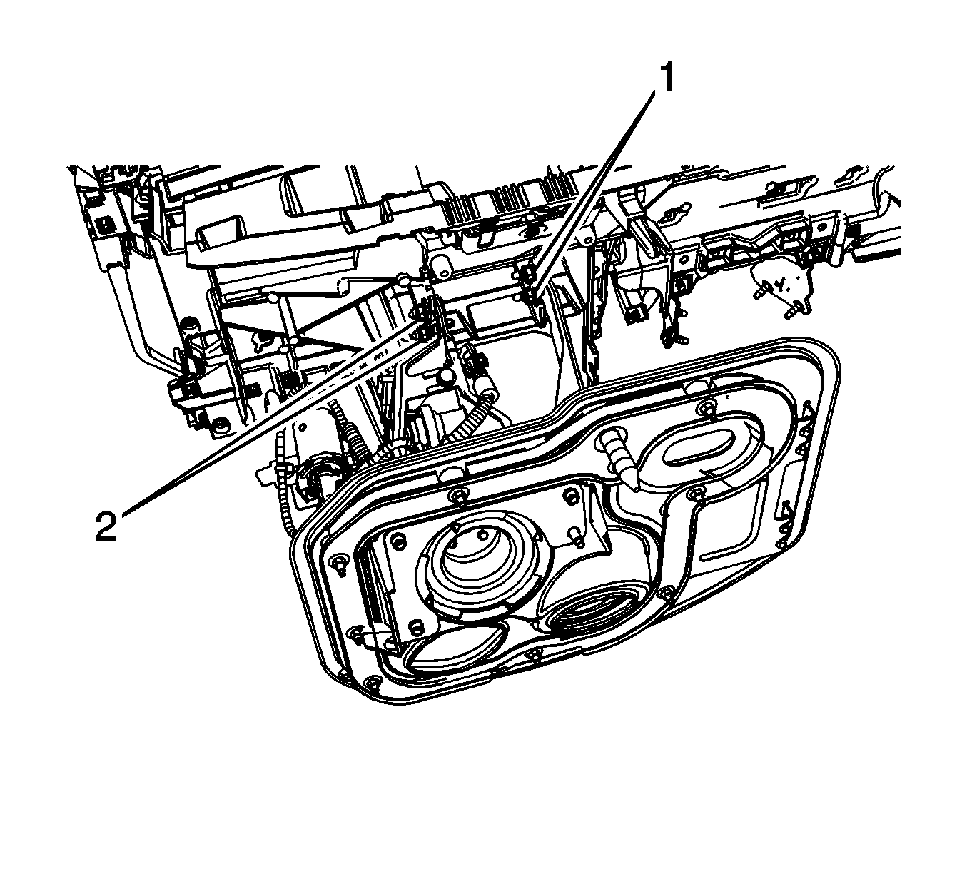
- Remove the 2 upper steering column support bracket nuts (1).
- Remove the 2 upper brake pedal assembly nuts (2).
- Remove the steering column support bracket (1).
- Carefully lower the brake pedal assembly to access the electrical connectors.
- Disconnect the brake pedal linear position sensor electrical connector (1).
- Disconnect the brake pedal position sensor electrical connector (2).
- Remove the adjustable brake pedal assembly.
Installation Procedure
- Using a suitable tool, slowly rotate the exposed end of the adjustable brake pedal actuator cable until the brake pedal assembly in the full forward, front of vehicle position. Do not use excessive rotating force on the adjustable brake pedal actuator cable.
- Using a square drive tool on the adjustable pedal motor, carefully rotate the adjustable pedal motor until the accelerator pedal is in the full forward, front of vehicle position. Do not use excessive rotating force on the adjustable pedal motor.
- Install the adjustable brake pedal assembly.
- Connect the brake pedal linear position sensor electrical connector (1).
- Connect the brake pedal position sensor electrical connector (2).
- Install the steering column support bracket (1).
- Install the vacuum brake booster mounting plate.
- Install the 2 upper steering column support bracket nuts (1).
- Install the 2 upper brake pedal assembly nuts (2).
- Install the brake pedal adjuster actuator cable (1) to the motor.
- Connect the accelerator pedal linear position sensor electrical connector (1) and install the clip to the brake pedal bracket.
- Position the accelerator pedal and motor assembly to the vacuum brake booster bracket studs.
- Install the lower steering column support bracket nut (2).
- Install the 2 lower adjustable pedal assembly bracket nuts (1).
- Install the vacuum brake booster mounting plate nut (1).
- Install the vacuum brake booster. Refer to Power Vacuum Brake Booster Replacement.
- Install the steering column. Refer to Steering Column Replacement.
- Calibrate the adjustable pedal system. Refer to Adjustable Pedal System Calibration.
Note: Ensure the adjustable brake pedal and the adjustable accelerator pedal are synchronized in the full forward, front of vehicle position.
Specification
Do not exceed 0.5 N·m (4.43 lb ft) of rotating force.
Specification
Do not exceed 0.5 N·m (4.43 lb ft) of rotating force.


Caution: Refer to Fastener Caution in the Preface section.

Tighten
Tighten the nuts to 25 N·m (18 lb ft).
Tighten
Tighten the nuts to 25 N·m (18 lb ft).

Ensure the adjustable brake pedal actuator cable engages the adjustable pedal motor drive fully and the collar is locked into place.

Tighten
Tighten the nut to 25 N·m (18 lb ft).

Tighten
Tighten the nuts to 25 N·m (18 lb ft).

Tighten
Tighten the nut to 25 N·m (18 lb ft).
Brake Pedal Assembly Replacement LHD
Removal Procedure
- Remove the vacuum brake booster. Refer to Power Vacuum Brake Booster Replacement.
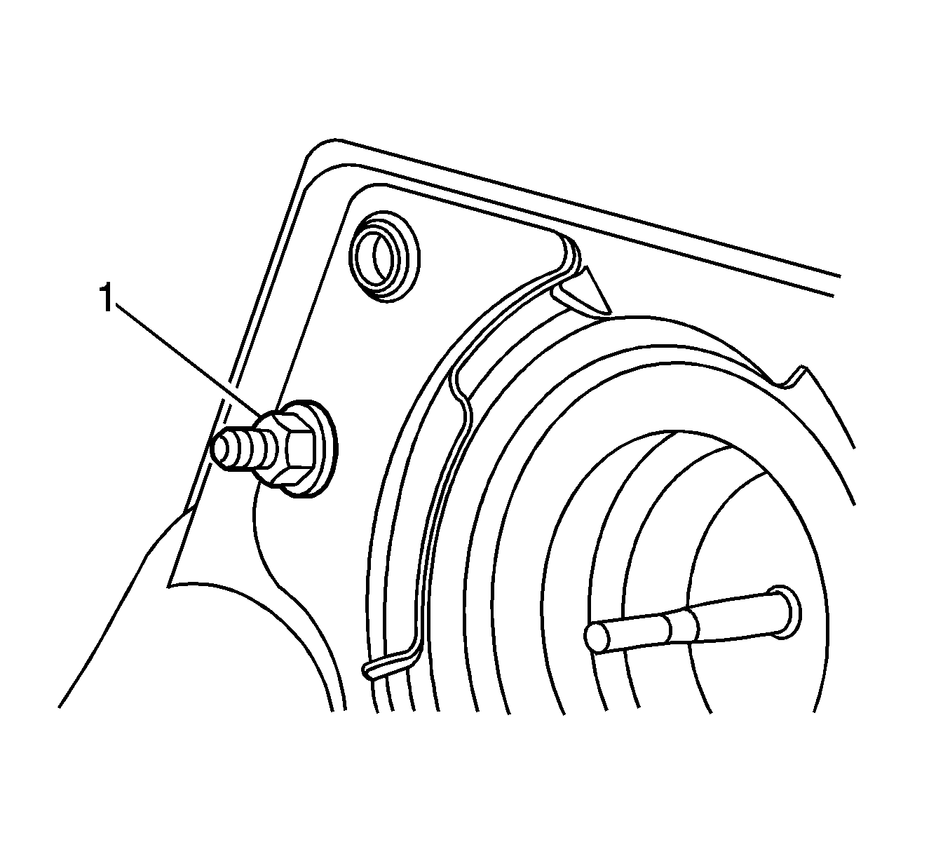
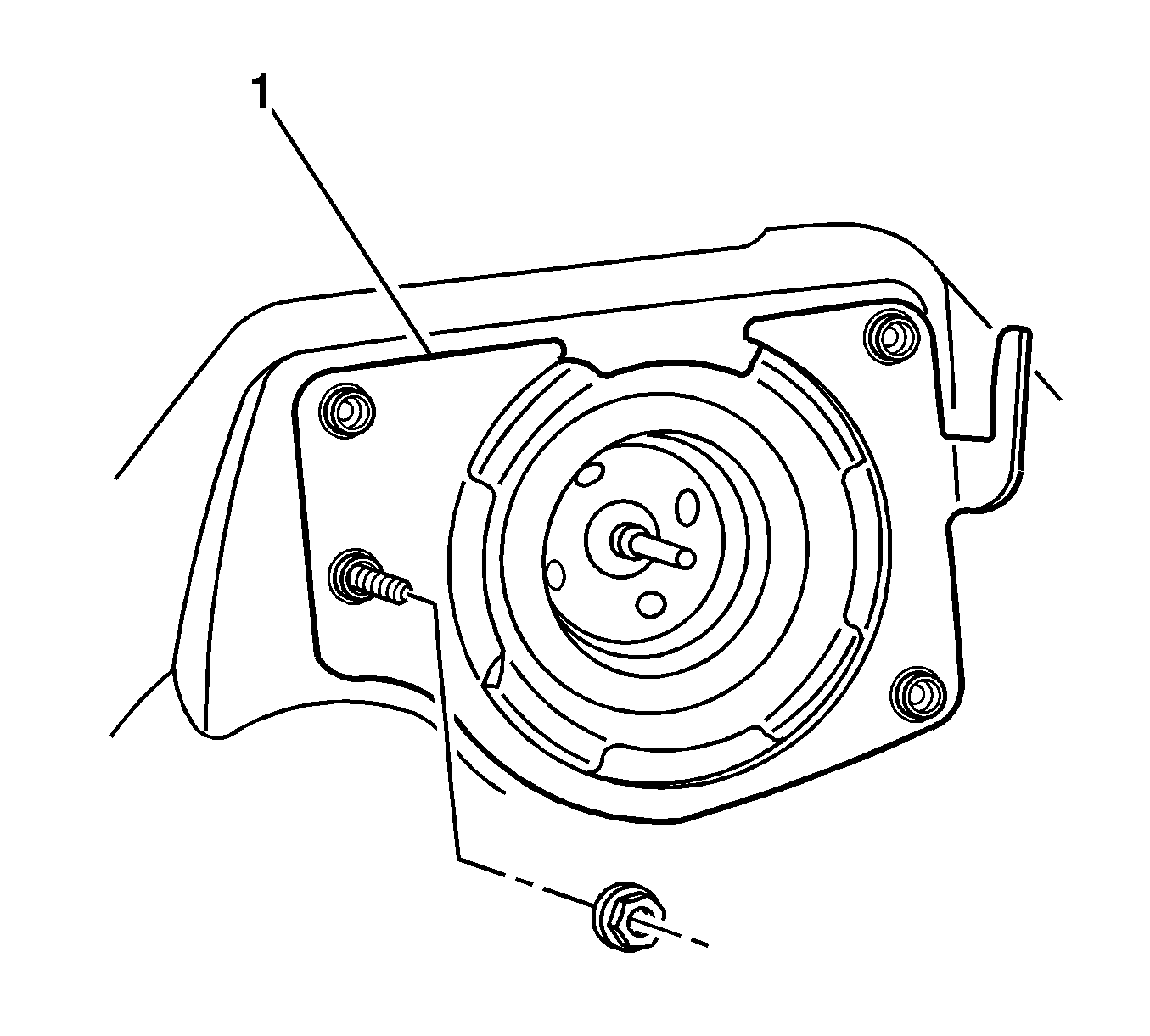
- Remove the vacuum brake booster mounting plate mounting nut (1).
- Without disconnecting the park brake cable, remove and position the park brake pedal assembly aside. Refer to Parking Brake Lever Pedal Assembly Replacement.
- Without disconnecting the steering column from the intermediate shaft, lower and support the steering column. Refer to Steering Column Replacement.
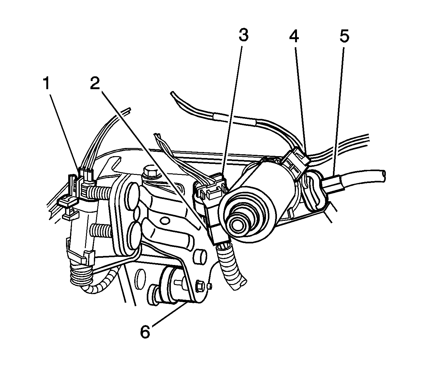
- Disconnect the brake pedal position sensor electrical connector (6).
- Disconnect the electrical connector (4) from the adjustable brake pedal motor.
- Disconnect the brake pedal linear position sensor electrical connector (1).
- Disconnect the adjustable accelerator pedal wiring harness (2) from the adjustable brake pedal bracket.
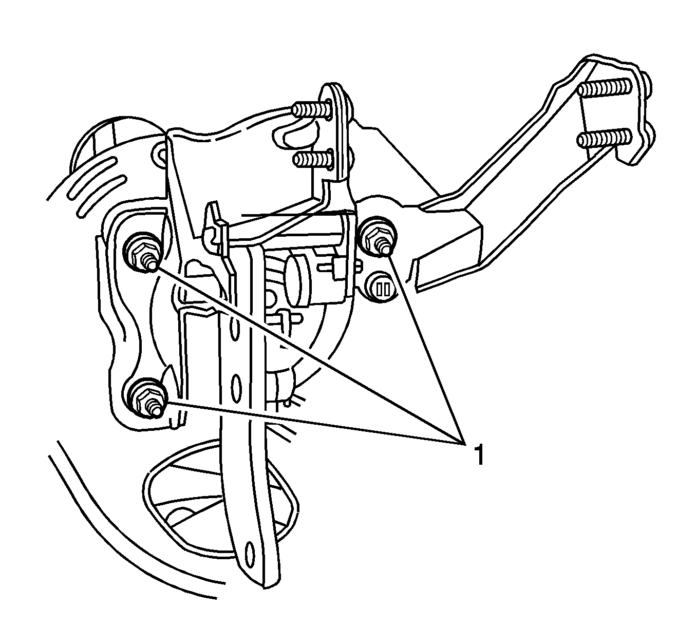
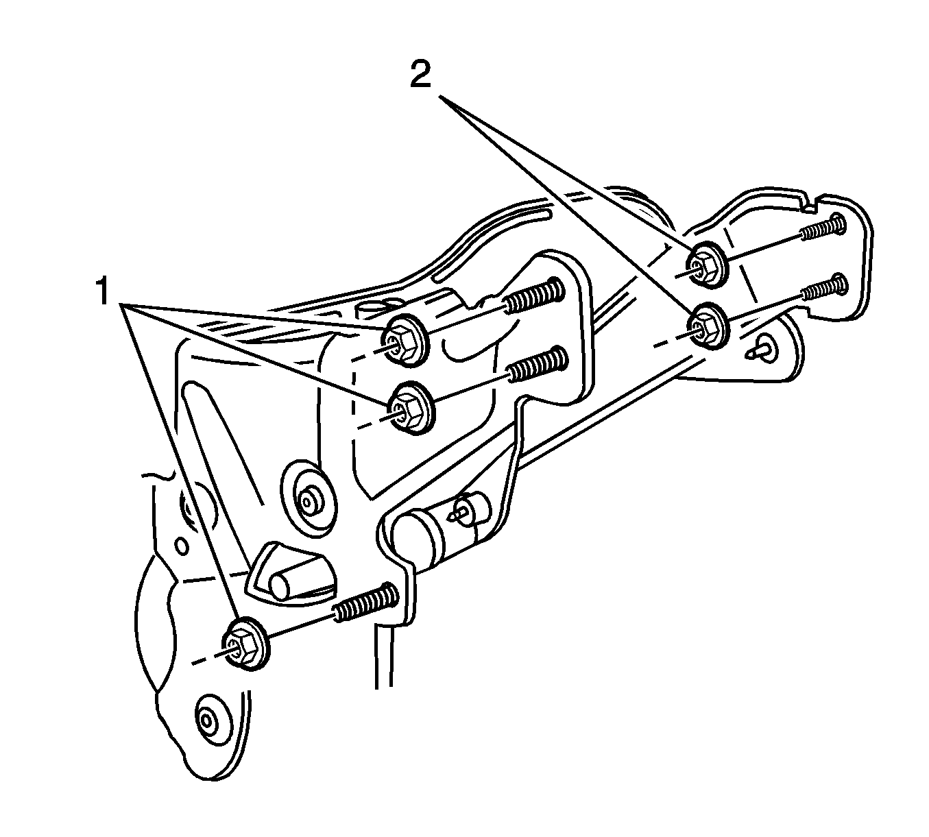
- Remove the 3 lower adjustable pedal assembly bracket nuts (1).
- Remove the 3 upper adjustable brake pedal assembly bracket nuts (1).
- Remove the 2 upper steering column support bracket nuts (2).
- Remove the vacuum brake booster mounting plate (1).
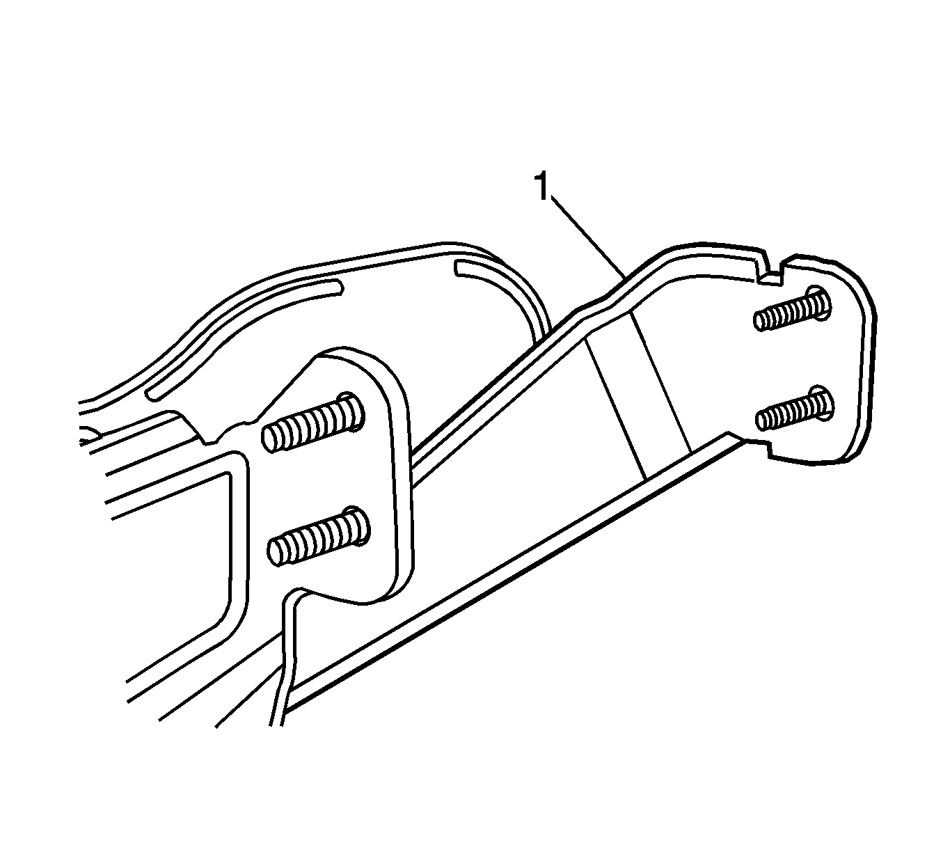
- Remove the steering column support bracket (1).
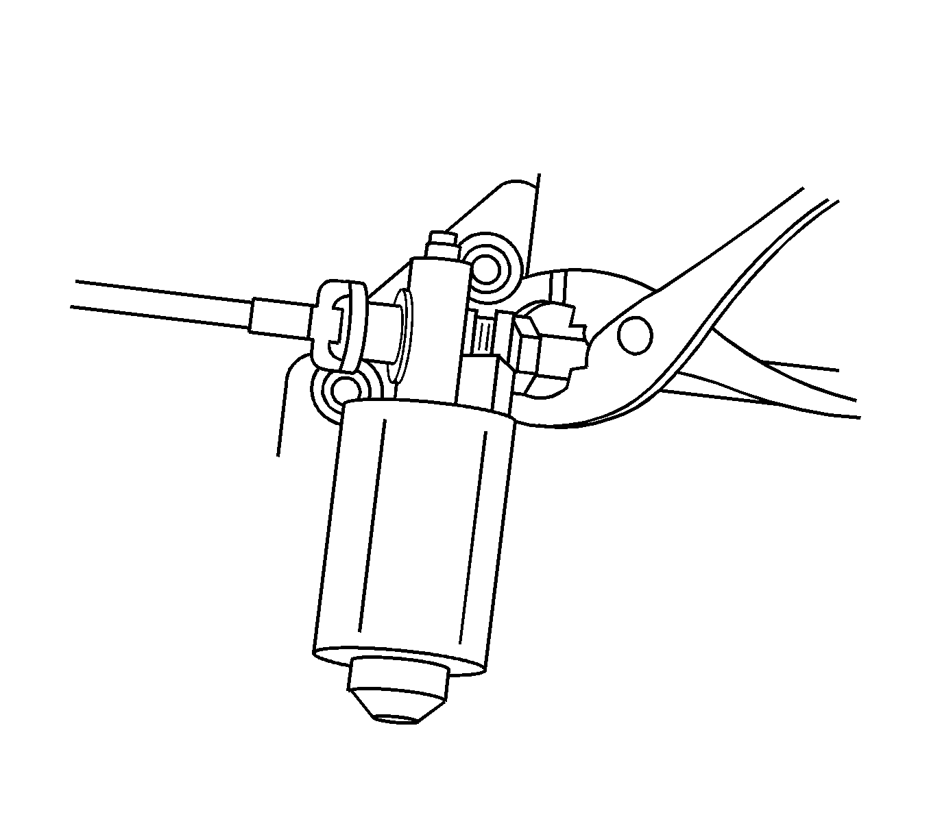
- Carefully squeeze the collar of the adjustable accelerator pedal cable and disconnect the accelerator pedal cable from the adjustable brake pedal motor.
- Remove the brake pedal assembly from the vehicle.
Installation Procedure
- Using a suitable tool, slowly rotate the exposed end of the adjustable accelerator pedal actuator cable. Do not use excessive rotating force on the adjustable accelerator actuator cable.
- Using a square drive tool on the adjustable pedal motor, carefully rotate the adjustable pedal motor until the brake pedal is in the full forward, front of vehicle position. Do not use excessive rotating force on the adjustable pedal motor.
- Install the adjustable brake pedal assembly to the vehicle.
- Install the adjustable accelerator pedal cable (5) to the motor.
- Install the steering column support bracket (1).
- Install the vacuum brake booster mounting plate (1).
- Install the 3 lower adjustable pedal assembly bracket nuts (1).
- Install the 3 upper adjustable pedal assembly bracket nuts (1).
- Install the vacuum brake booster mounting plate nut (1).
- Install the 2 upper steering column support bracket nuts (2).
- Connect the brake pedal linear position sensor electrical connector (1).
- Connect the accelerator pedal linear position sensor electrical connector clip (2) to the adjustable pedal bracket.
- Connect the electrical connector (4) to the adjustable brake pedal motor.
- Connect the brake pedal position sensor electrical connector (6).
- Install the steering column. Refer to Steering Column Replacement.
- Install the park brake pedal assembly. Refer to Parking Brake Lever Pedal Assembly Replacement.
- Install the vacuum brake booster. Refer to Power Vacuum Brake Booster Replacement.
- Calibrate the adjustable pedal system. Refer to Adjustable Pedal System Calibration.
Note: Ensure the adjustable brake pedal and the adjustable accelerator pedal are synchronized in the full forward, front of vehicle position.
Specification
Do not exceed 0.5 N·m (4.43 lb in) of rotating force.
Specification
Do not exceed 0.5 N·m (4.43 lb in) of rotating force.

Ensure the adjustable accelerator pedal cable engages the adjustable pedal motor drive fully and the collar is locked into place.


Caution: Refer to Fastener Caution in the Preface section.

Tighten
Tighten the nuts to 25 N·m (18 lb ft).

Tighten
Tighten the nuts to 25 N·m (18 lb ft).

Tighten
Tighten the nut to 25 N·m (18 lb ft).

Tighten
Tighten the nuts to 25 N·m (18 lb ft).

