For 1990-2009 cars only
Removal Procedure
Warning: Refer to Approved Equipment for Collision Repair Warning in the Preface section.
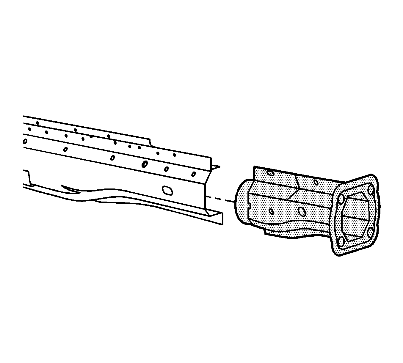
Note: If front rail damage is limited to 205 mm (8 in) from the front end, a pre-sleeved service section is available. This service section includes the front bumper mounting bracket.
- Disable the SIR system. Refer to SIR Disabling and Enabling.
- Disconnect the negative battery cable. Refer to Battery Negative Cable Disconnection and Connection.
- Remove all of the related panels and the components, including the left front wheelhouse mounting bracket to the rail.
- Remove the sealers and anti-corrosion materials from the repair area, as necessary. Refer to Anti-Corrosion Treatment and Repair.
- Repair as much as the damage as possible.
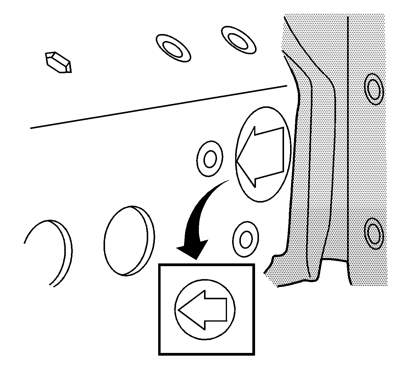
- Locate the die marks on the inner and outer rail.
- Locate the die marks on the front rail.
- Scribe a line 360 degrees around the frame rail at the die marks.
- Cut at the marked location.
- Remove the damaged component from the vehicle.


Note: Do not damage the rail behind the die marks.
Installation Procedure
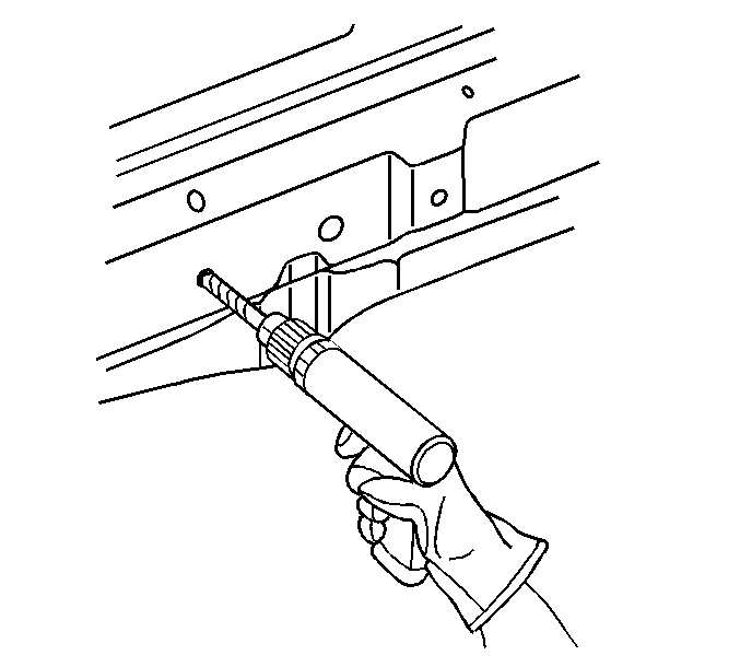
- Drill 4 plug weld holes; 2 at the inside and 2 at the outside, 13 mm (1/2 in) from the cut line and 50 mm (2 in) apart on the existing frame rail.
- Apply 3M Weld-Thru Coating P/N 05913 or equivalent to all mating surfaces.
- Install and position the replacement service section using 3-dimensional measuring.
- Tack weld the part into position at the initial plug weld holes.
- Inspect the service part for proper dimensions using 3-dimensional measuring equipment.
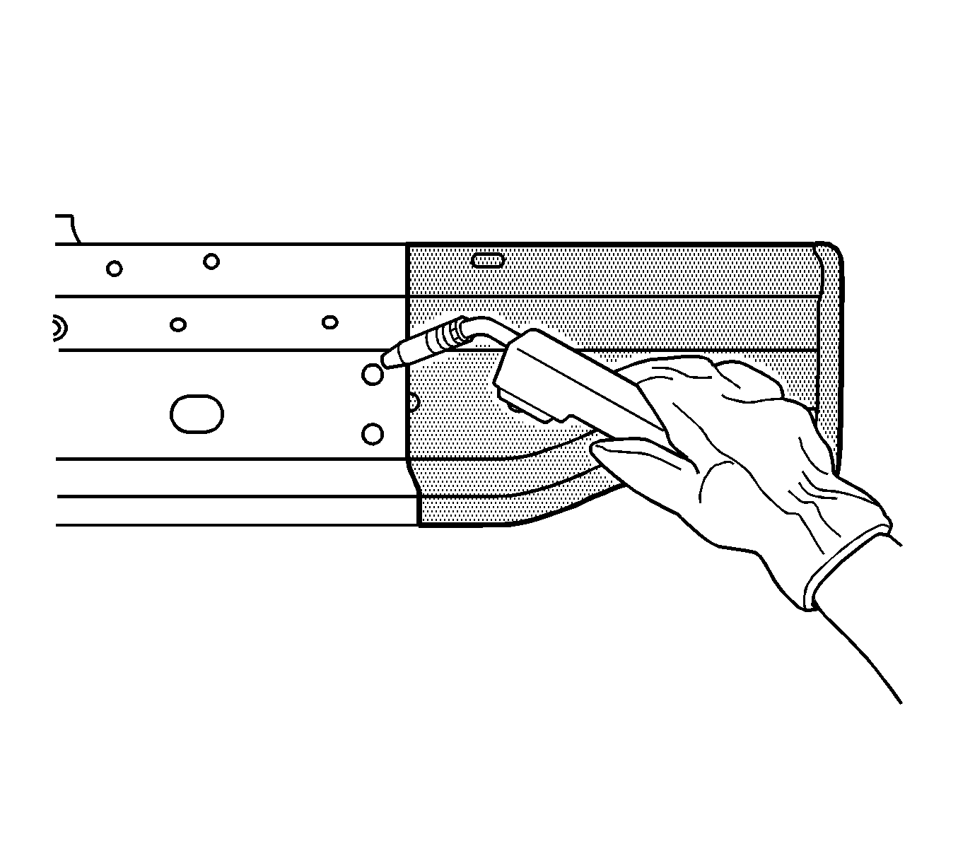
- Stitch weld along the entire sectioning joint. Make 25 mm (1 in) welds along the seam with 25 mm (1 in) gaps between.
- Complete the stitch weld.
- Clean and prepare the welded surfaces.
- Position the tie bar mounting bracket. Weld the bracket in place.
- Install all of the related panels and components.
- Apply the sealers and anti-corrosion materials to the repair area, as necessary. Refer to Anti-Corrosion Treatment and Repair.
- Paint the repaired area. Refer to Basecoat/Clearcoat Paint Systems.
- Enable the SIR system. Refer to SIR Disabling and Enabling.
- Connect the negative battery cable. Refer to Battery Negative Cable Disconnection and Connection.


