For 1990-2009 cars only
Removal Procedure
Warning: Refer to Approved Equipment for Collision Repair Warning in the Preface section.
Note:
• If the damage exceeds the recommended area for sectioning and the rail cannot be straightened, then replace the entire rail. • Sectioning procedures have been developed to simplify the repair of the lower rails, as long as the damage rearward of the sectioning location can be repaired to factory specifications. • Failure to follow the instructions may lead to improper rail sectioning, which may compromise the structural integrity of the vehicle.
- Disable the SIR system. Refer to SIR Disabling and Enabling.
- Disconnect the negative battery cable. Refer to Battery Negative Cable Disconnection and Connection.
- Remove all of the related panels and components.
- Repair as much as the damage as possible to factory specifications.
- Note the location and remove the sealers and anti-corrosion materials from the repair area, as necessary. Refer to Anti-Corrosion Treatment and Repair.
- Perform the necessary procedures to gain access to the repair.
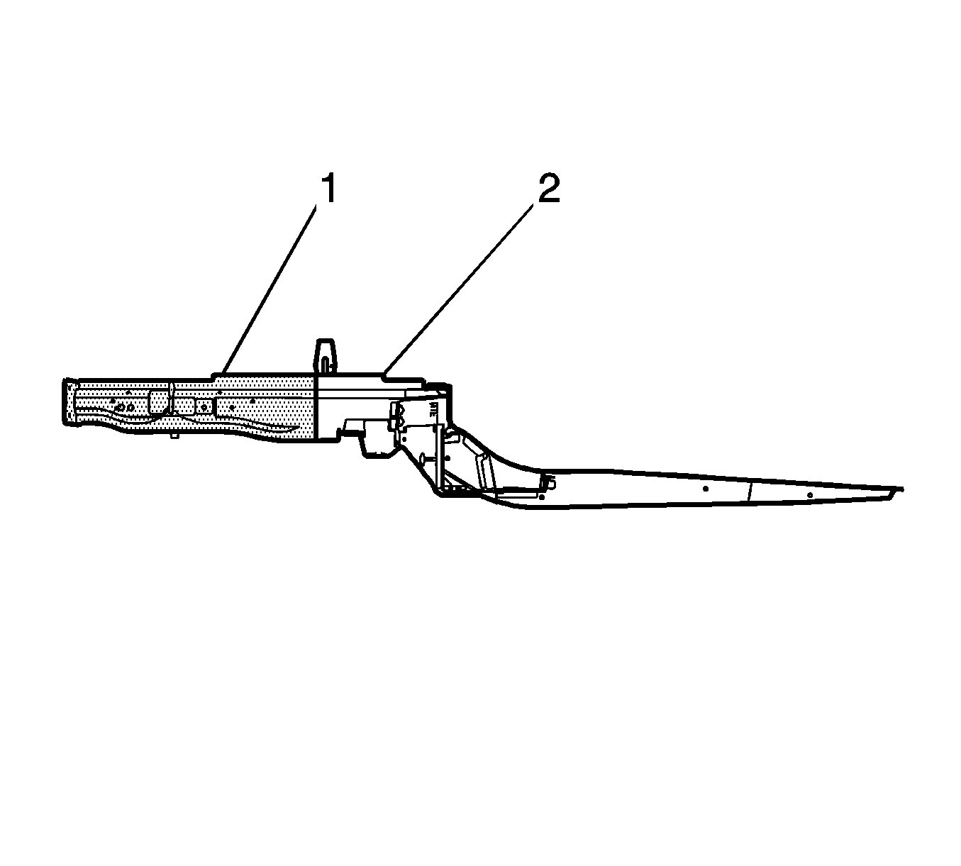
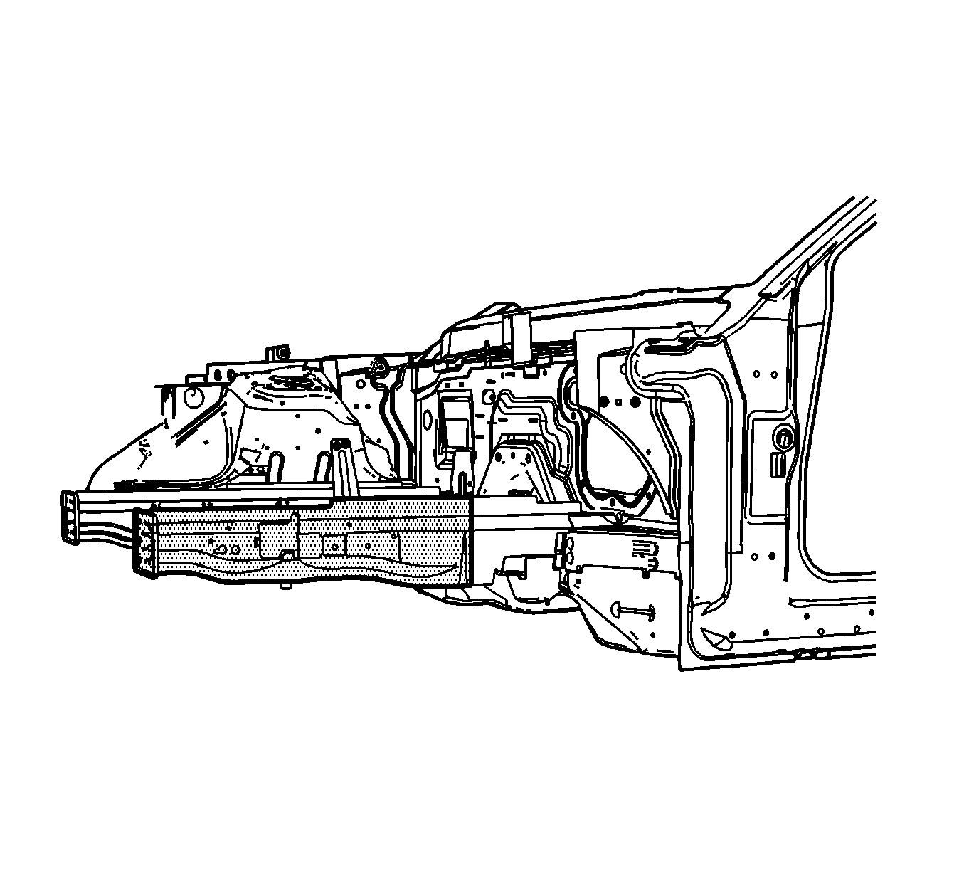
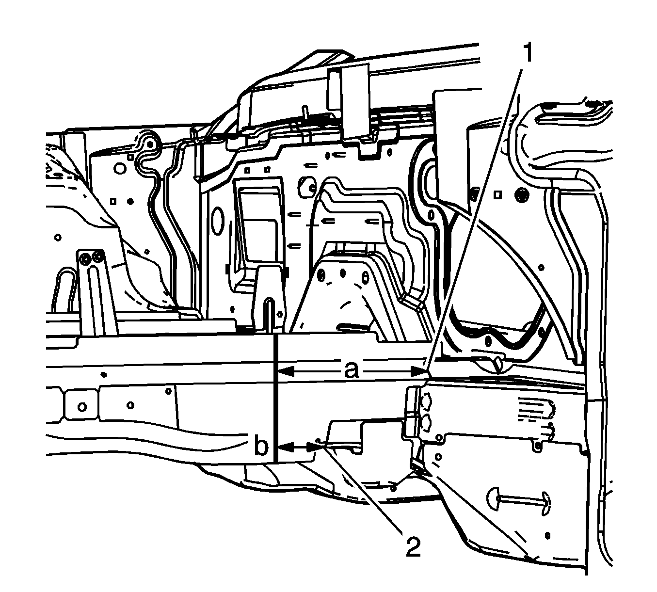
- On the outboard side of the rail, locate the upper reinforcement bracket (1). On the bottom of the rail, locate the lower reinforcement bracket (2).
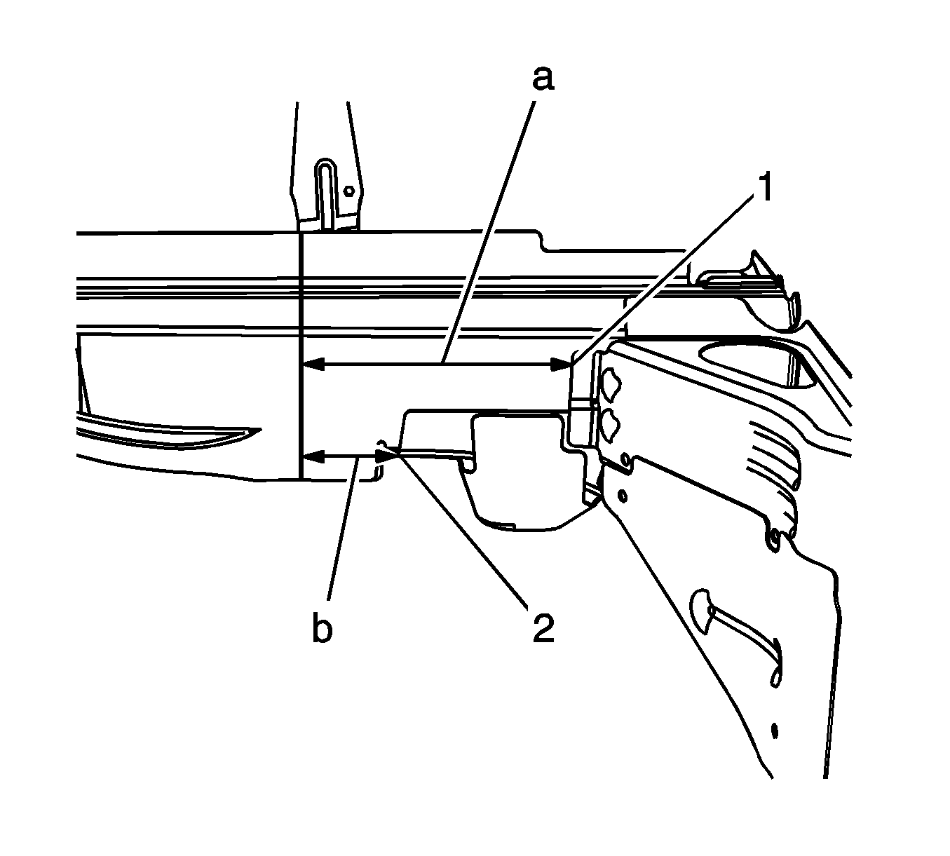
- Measure 280 mm (11 in) (a) forward from the edge of the upper reinforcement bracket (1). Make a mark.
- Measure 100 mm (4 in) (b) forward from the edge of the lower reinforcement bracket (2). Make a mark.
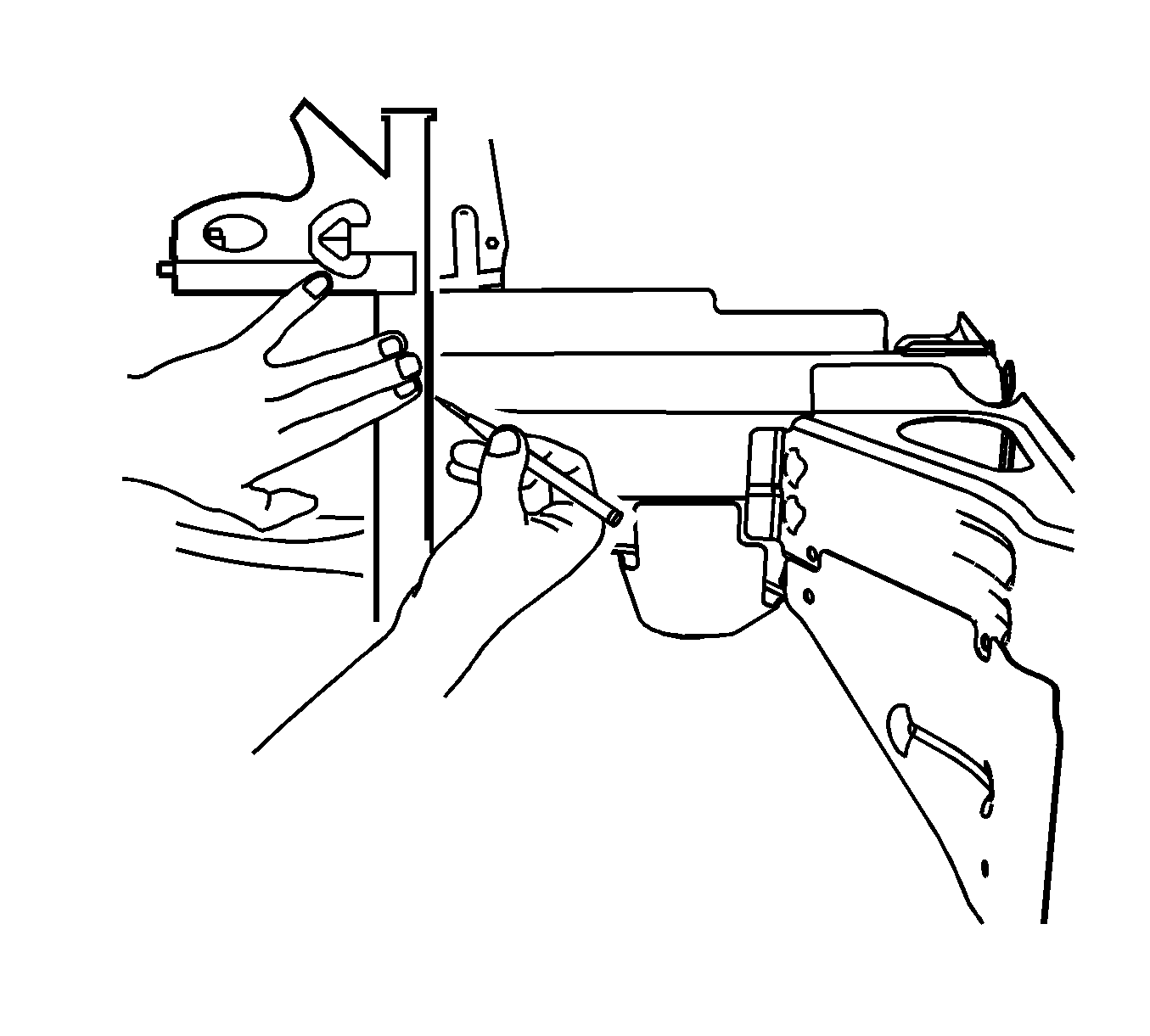
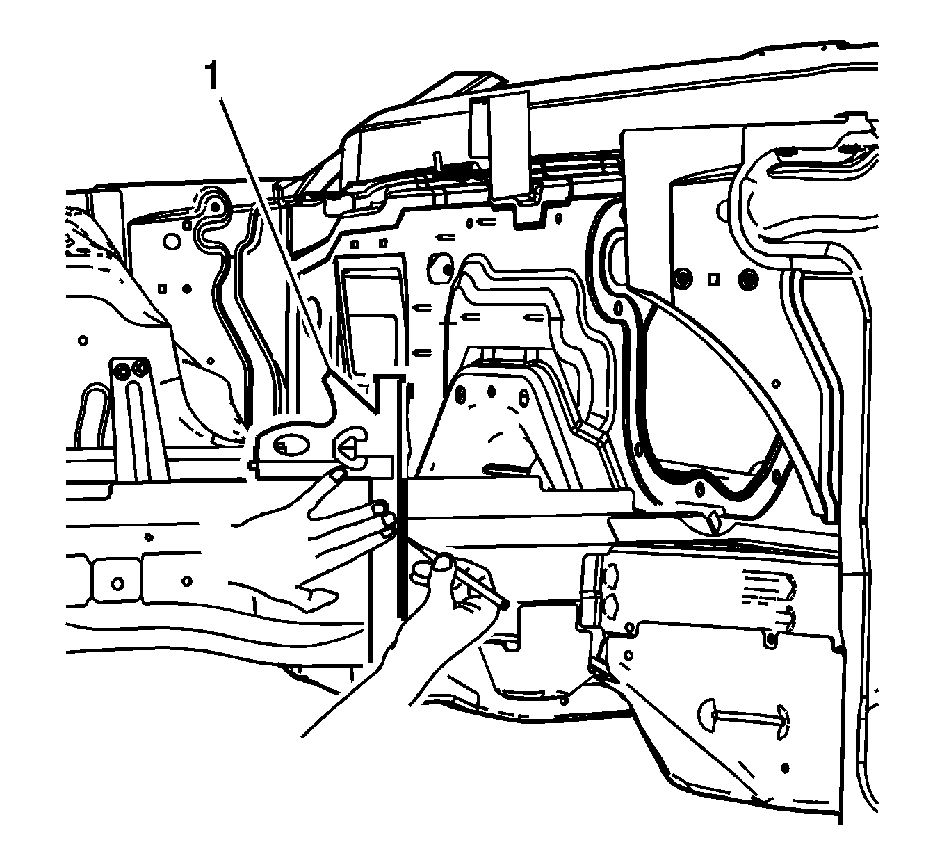
- Using the two marks, align a sliding square or similar tool (1) square to the surface to the vertical walls of the frame rail.
- Scribe a line to both sides of the frame rails.
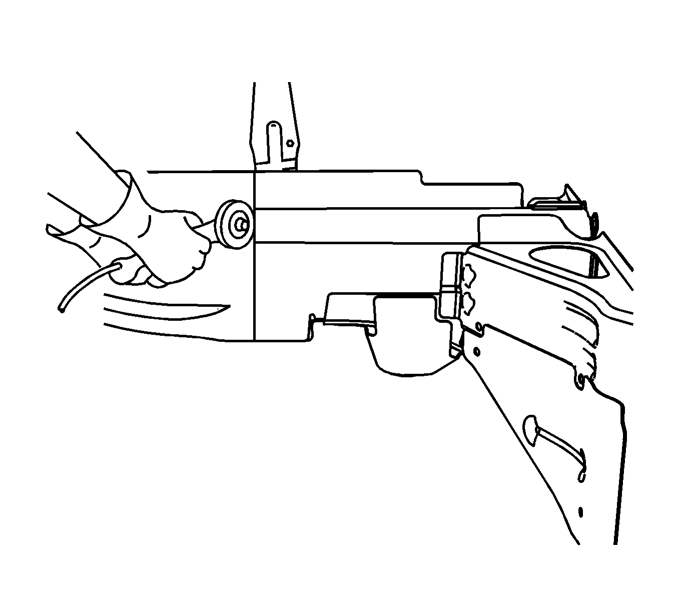
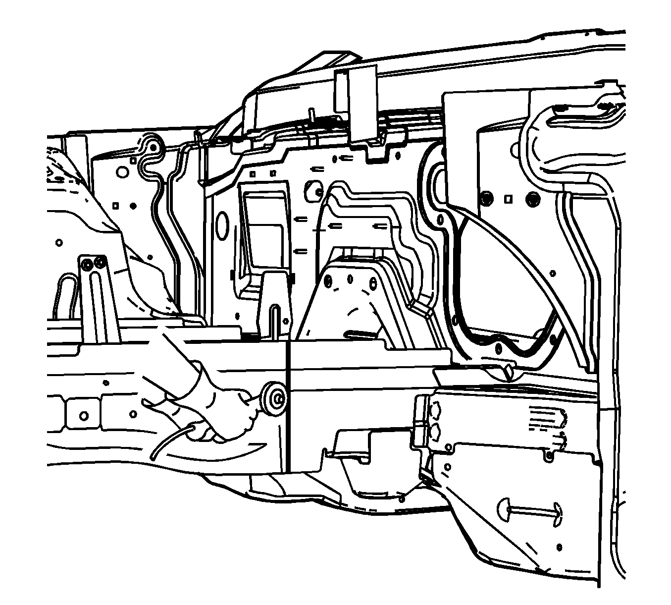
- Cut the frame rail at the marked location.
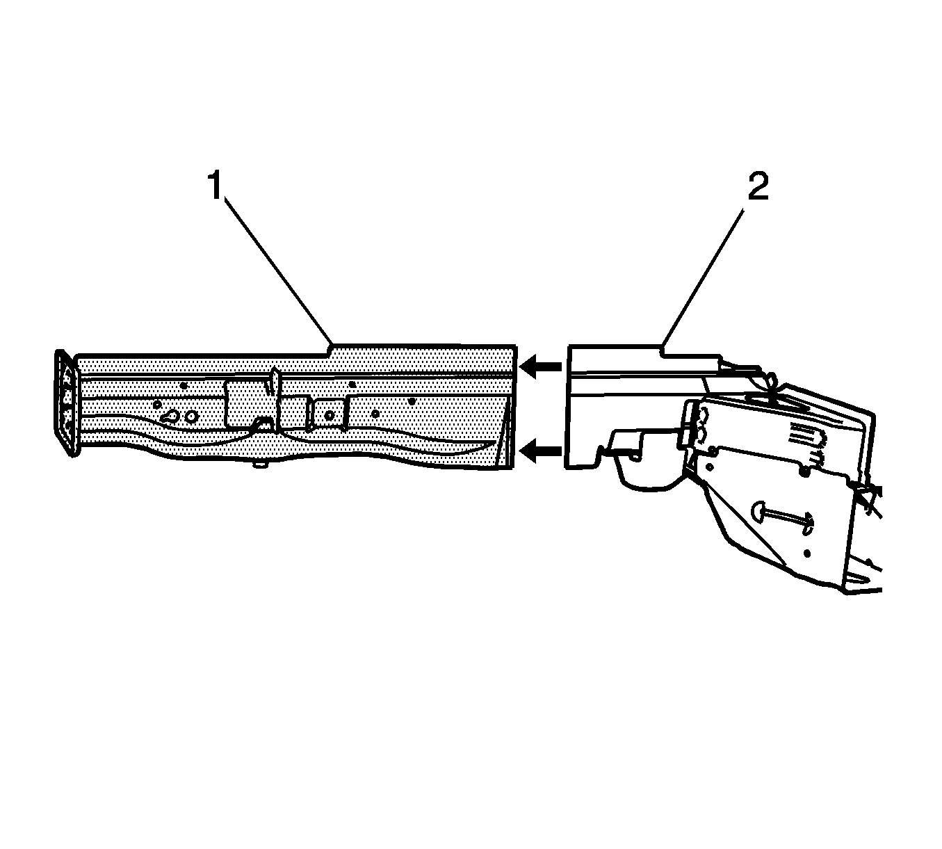
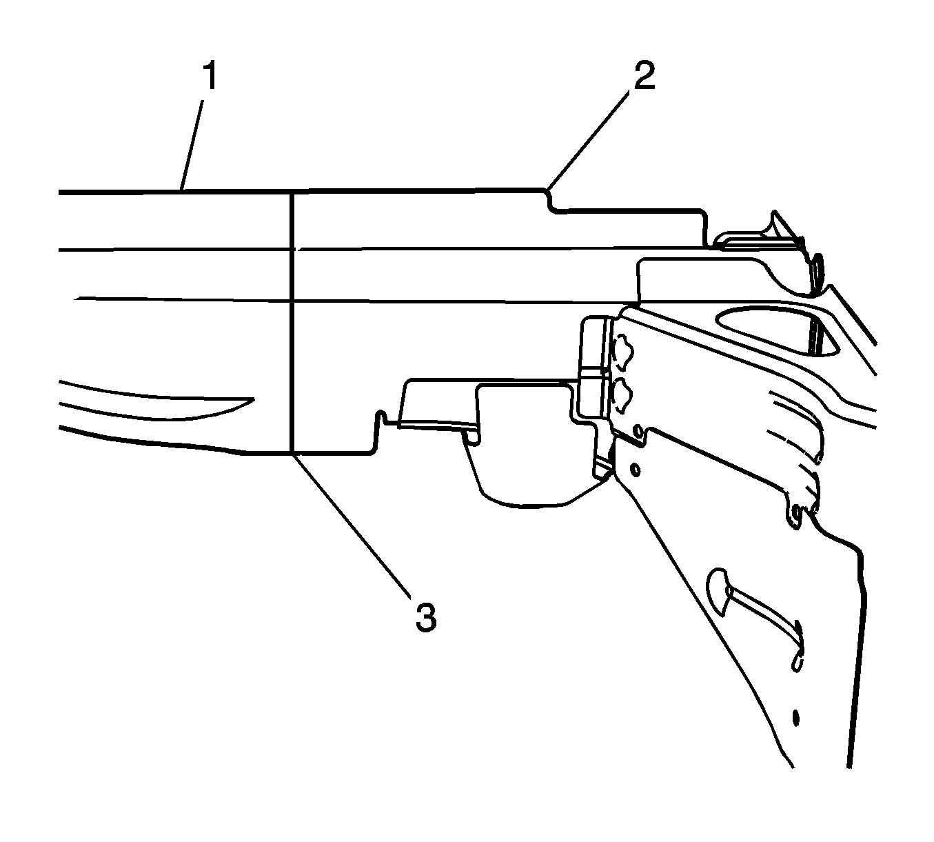
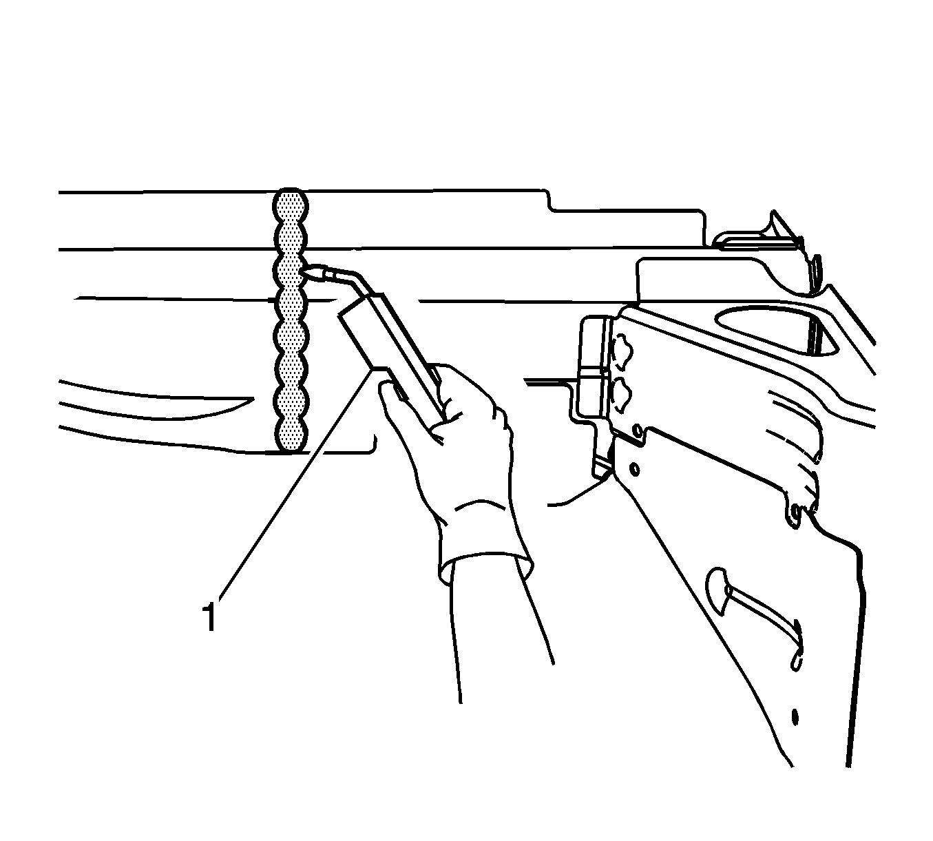
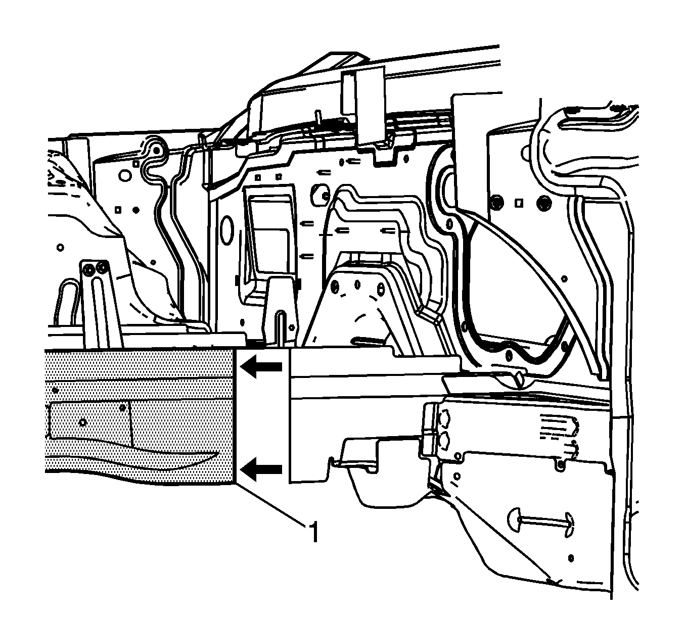
- Remove the damaged frame rail section (1) from the vehicle.
Warning: Refer to Foam Sound Deadeners Warning in the Preface section.
Installation Procedure
- In order to create the rail section service part (1), cut the full rail service part (2).
- On the outboard side of the full rail service part, locate the upper reinforcement bracket (1). On the bottom of the rail, locate the lower reinforcement bracket (2).
- Measure 280 mm (11 in) (a) forward from the edge of the upper reinforcement bracket (1). Make a mark.
- Measure 100 mm (4 in) (b) forward from the edge of the lower reinforcement bracket (2). Make a mark.
- Using the two marks, align a sliding square or similar tool square to the surface to the vertical walls of the frame rail.
- Scribe a line to both sides of the frame rails.
- Cut the frame rail at the marked location.
- Remove the rail section (1) from the full rail service part.
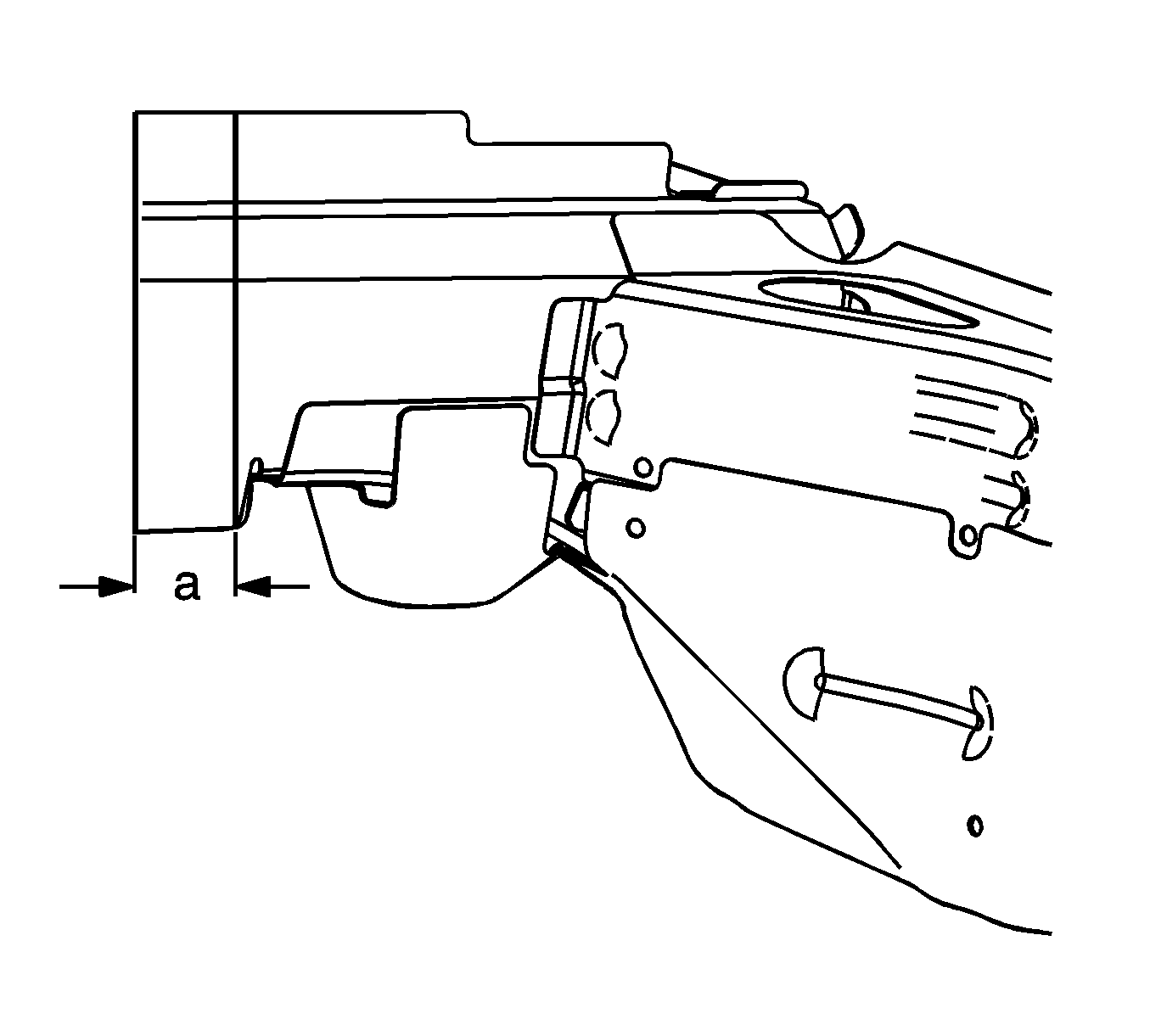
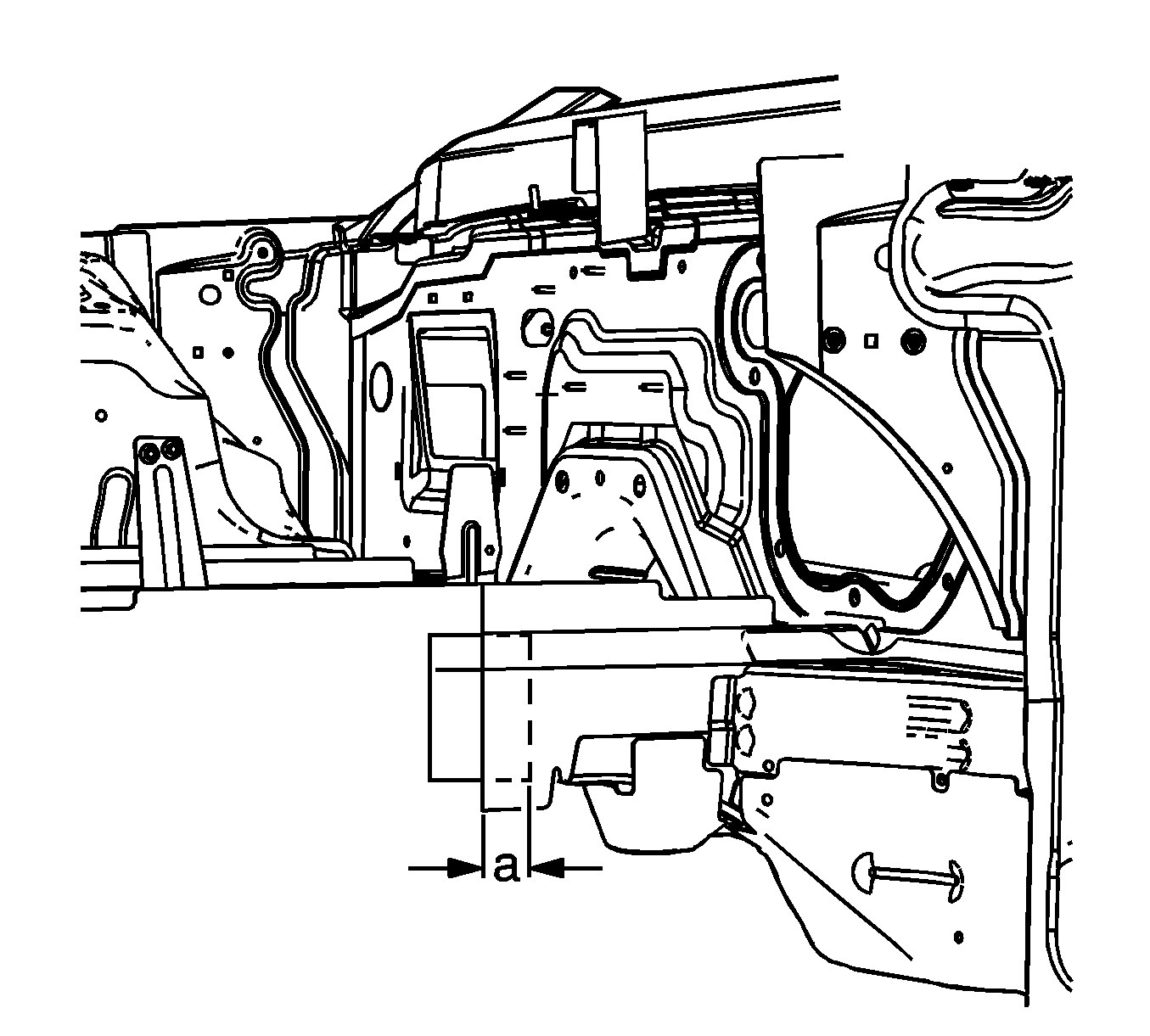
- From the unused portion of the full rail service part, measure, mark, and cut a 50 mm (2 in) (a) section of rail to be used as a sleeve or backing plate for the sectioning joint.
- Cut through the top and the bottom of the sleeve to create two individual pieces that can be installed in the near rail section.
- Trim the pieces as necessary to provide a flush fit along the inner surface of the new rail section.
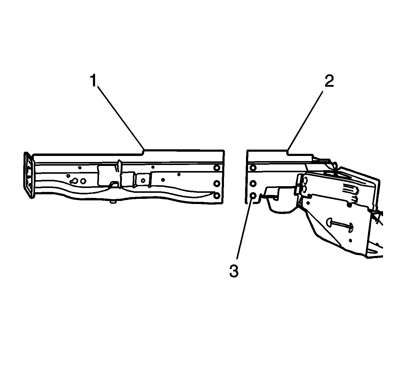
- Drill 6 8 mm (5/16 in) (3) plug weld holes in the rail section (1), so that there are 3 holes equally spaced on each side of the rail.
- Drill 6 8 mm (5/16 in) (3) plug weld holes in the vehicle rail (2), so that there are 3 holes equally spaced on each side of the rail.
- Clean and prepare all of the welded surfaces.
- Apply 3M weld-thru coating P/N 05916 or equivalent as necessary.
- Install the 2 sleeve pieces 25 mm (1 in) (a) into the vehicle frame rail.
- Plug weld accordingly at each plug weld location.
- Position the service rail section (1) to the existing rail (2).
- Maintain a gap (3) of 1 1/2 times the frame rail metal thickness at the sectioning joint. Clamp in place.
- Inspect the frame measurements 3-dimensional to ensure proper position of the service rail section.
- Plug weld accordingly at each plug weld location.
- Inspect the frame measurements 3-dimensional to ensure proper position of the service rail section.
- Stitch weld along the entire sectioning joint. Make 25 mm (1 in) welds along the seam with 25 mm (1 in) gaps between.
- Complete the stitch weld (1).
- Clean and prepare all of the welded surfaces.
- Install all of the related panels and components.
- Apply the sealers and anti-corrosion materials to the repair area, as necessary. Refer to Anti-Corrosion Treatment and Repair.
- Paint the repaired area. Refer to Basecoat/Clearcoat Paint Systems.
- Connect the negative battery cable. Refer to Battery Negative Cable Disconnection and Connection.
- Enable the SIR system. Refer to SIR Disabling and Enabling.
