For 1990-2009 cars only
Steering Column Lock Control Module Replacement Domestic Vehicles
Removal Procedure
- Remove the knee bolster. Refer to Driver Knee Bolster Bracket Replacement .
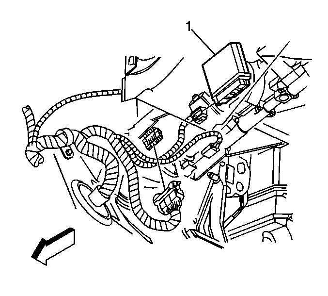
- Disconnect the electrical connectors to the steering column module (1).
- Loosen the retaining screw on the steering column control module. Slide the control module out of the retaining bracket.

Installation Procedure
- Install the control module (1) to the steering column and tighten the retaining screw.
- Connect the electrical connectors on the steering column control module.
- Install the knee bolster. Refer to Driver Knee Bolster Bracket Replacement .
- Program the steering column control module. Refer to Steering Column Lock Control Module Programming and Setup .
Notice: Refer to Fastener Notice in the Preface section.

Tighten
Tighten screw to 5 N·m (44 lb in).
Steering Column Lock Control Module Replacement Export Vehicles
Removal Procedure
- Remove the steering column. Refer to Steering Column Replacement.
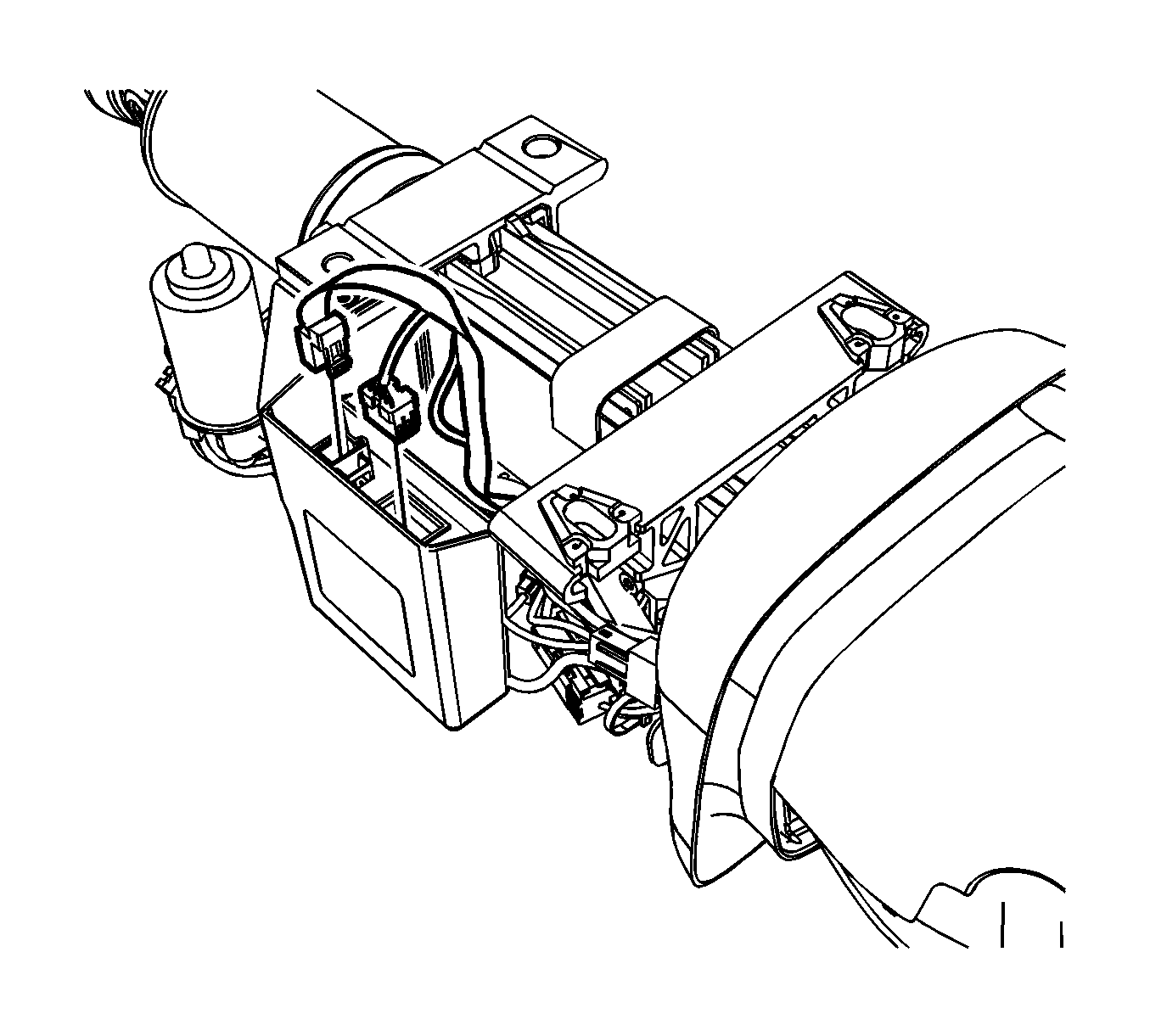
- Disconnect the electrical connectors from the steering column lock control module.
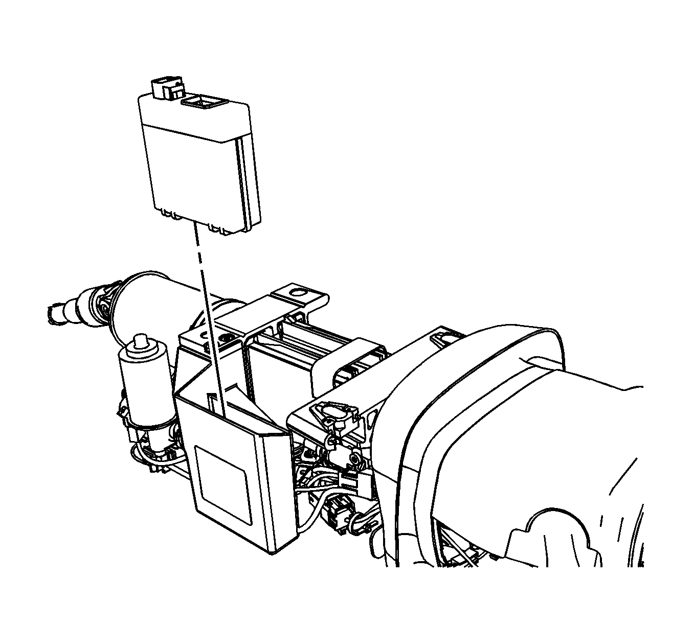
- Depress the locking tabs and remove the steering column lock control module from the support bracket.


Installation Procedure
- Install the steering column lock control module to the support bracket.
- Connect the electrical connectors to the steering column lock control module.
- Install the steering column. Refer to Steering Column Replacement.
- Program the steering column control module. Refer to Steering Column Lock Control Module Programming and Setup .


