GM Service Manual Online
For 1990-2009 cars only
Makes
🢒
Cadillac
🢒
2005
🢒
STS
🢒
Vehicle Control Systems
🢒
Vehicle DTC Information
🢒 Instrument Cluster Schematics
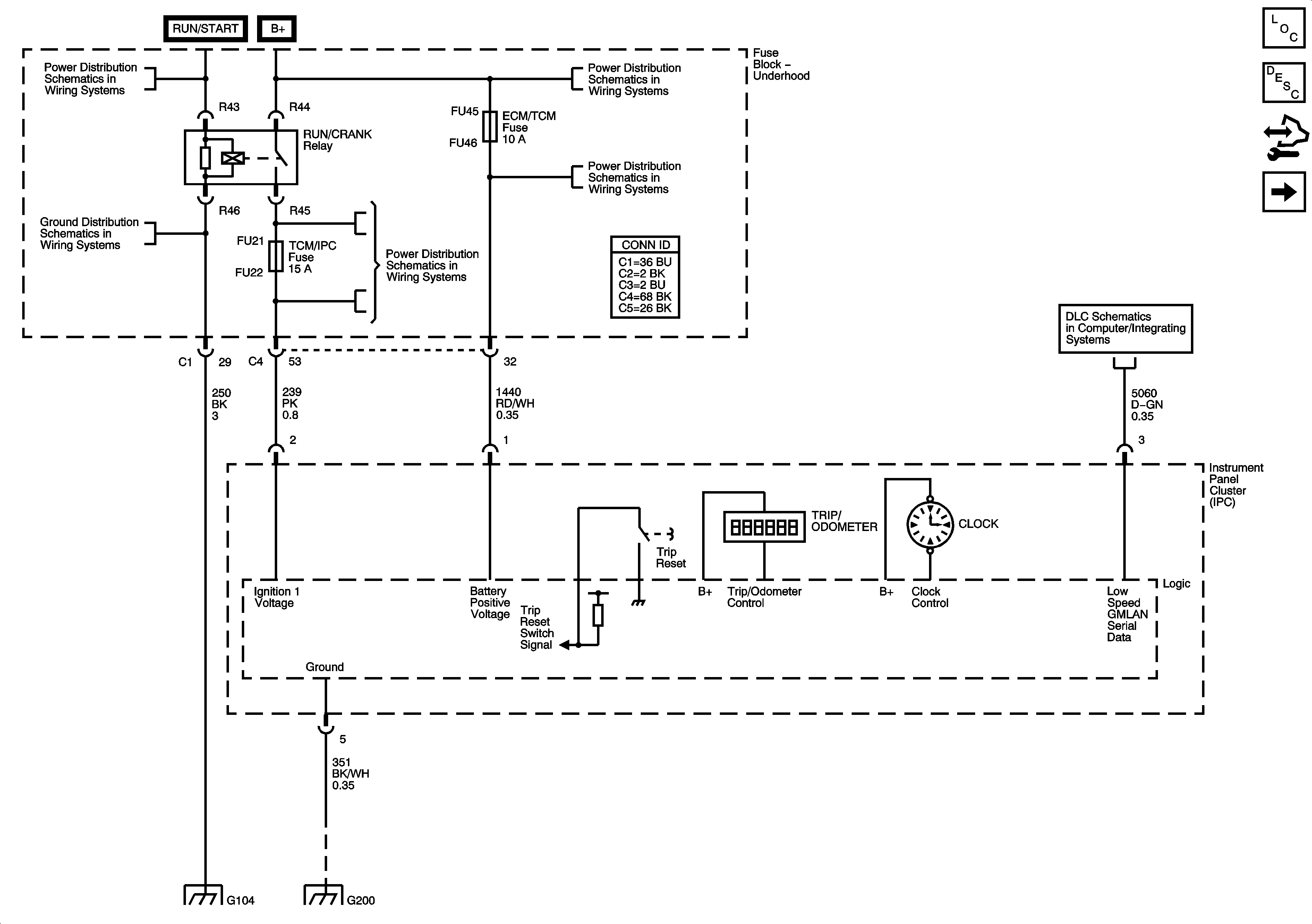
Figure
1:
Power, Ground, DLC, Odometer and Clock
Master Electrical Component List
Instrument Cluster Description and Operation
Control Module References
Indicators
Fuse Block Right Rear: LT Turn Signal, RIM(1), Rear Fog Lamp, FT Passenger Door Module, Heated Steering Column, IGN 1, RIM(2) and Airbag Fuses; Rear Fog Lamp and IGN 1 Relays
G104 (1 of 2)
Fuse Block-Underhood: Starter IGN 1 Relays; Starter, Starter Relay, CCP, TCM/IPM/ECM, MAF, ABS and Washer Nozzle/ACC Fuses
Fuse Block Underhood Bussing
Fuse Block-Underhood Fuses/Relay: IPM/ALDL, Auto Headlamp Dimming, CCP, ECM/TCM, WPR MOD, WPR SW/VICS and Rain Sensor/HDLP Wash Fuses. Accessory Relay
GMLAN Low Speed 2 of 2
G104 (1 of 2)
G200 (2 of 2)
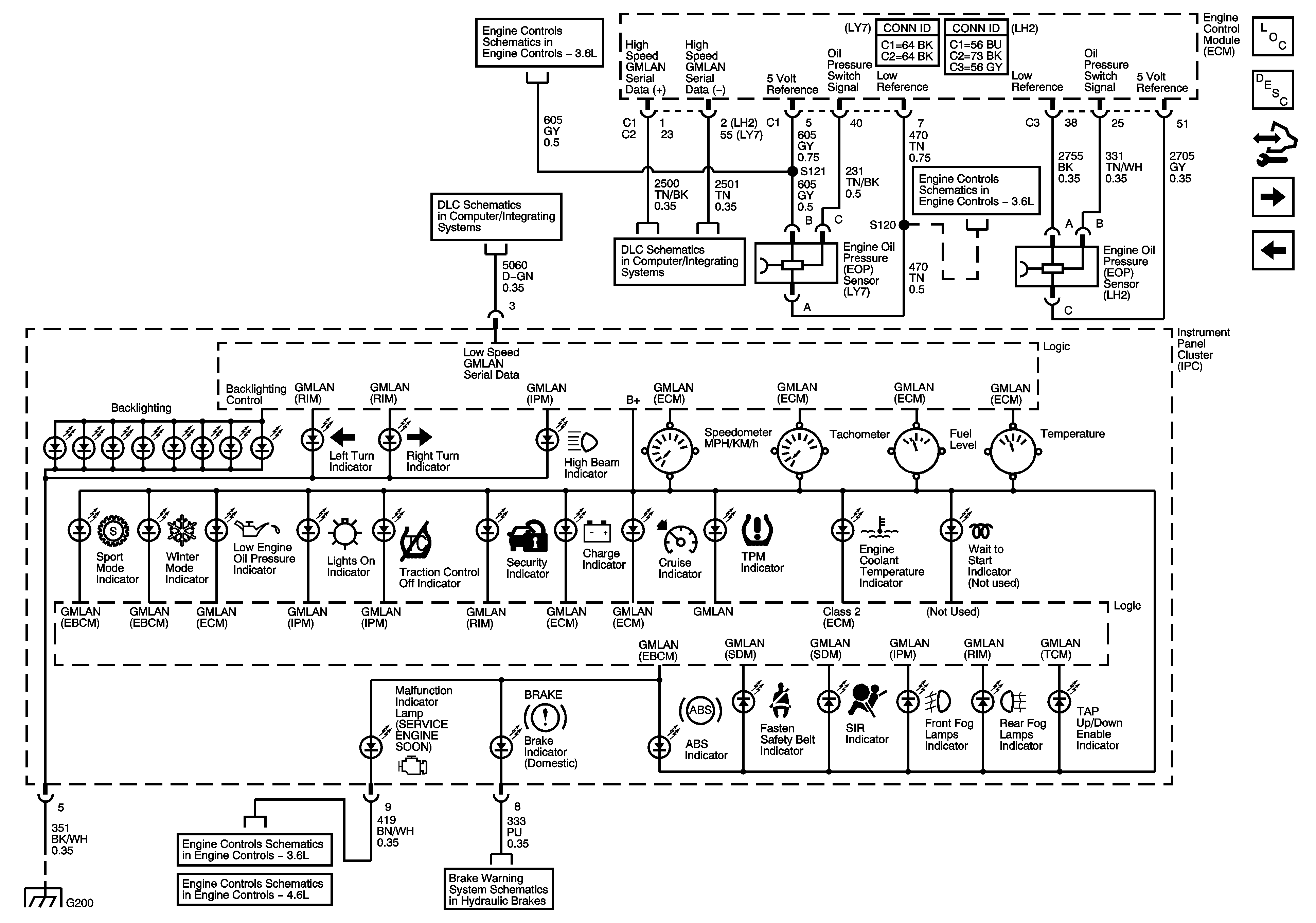
Figure
2:
Indicators
Master Electrical Component List
Instrument Cluster Description and Operation
Control Module References
DIC/Dimmer Switch
Power, Ground, Odometer and Clock
Engine Data Sensors - 5 Volt Reference Bus
GMLAN Low Speed 2 of 2
GMLAN High Speed - Domestic w/UE1
Engine Data Sensors - Low Reference Bus
ECM Power, Ground, DLC and MIL
Brake Warning System Schematics
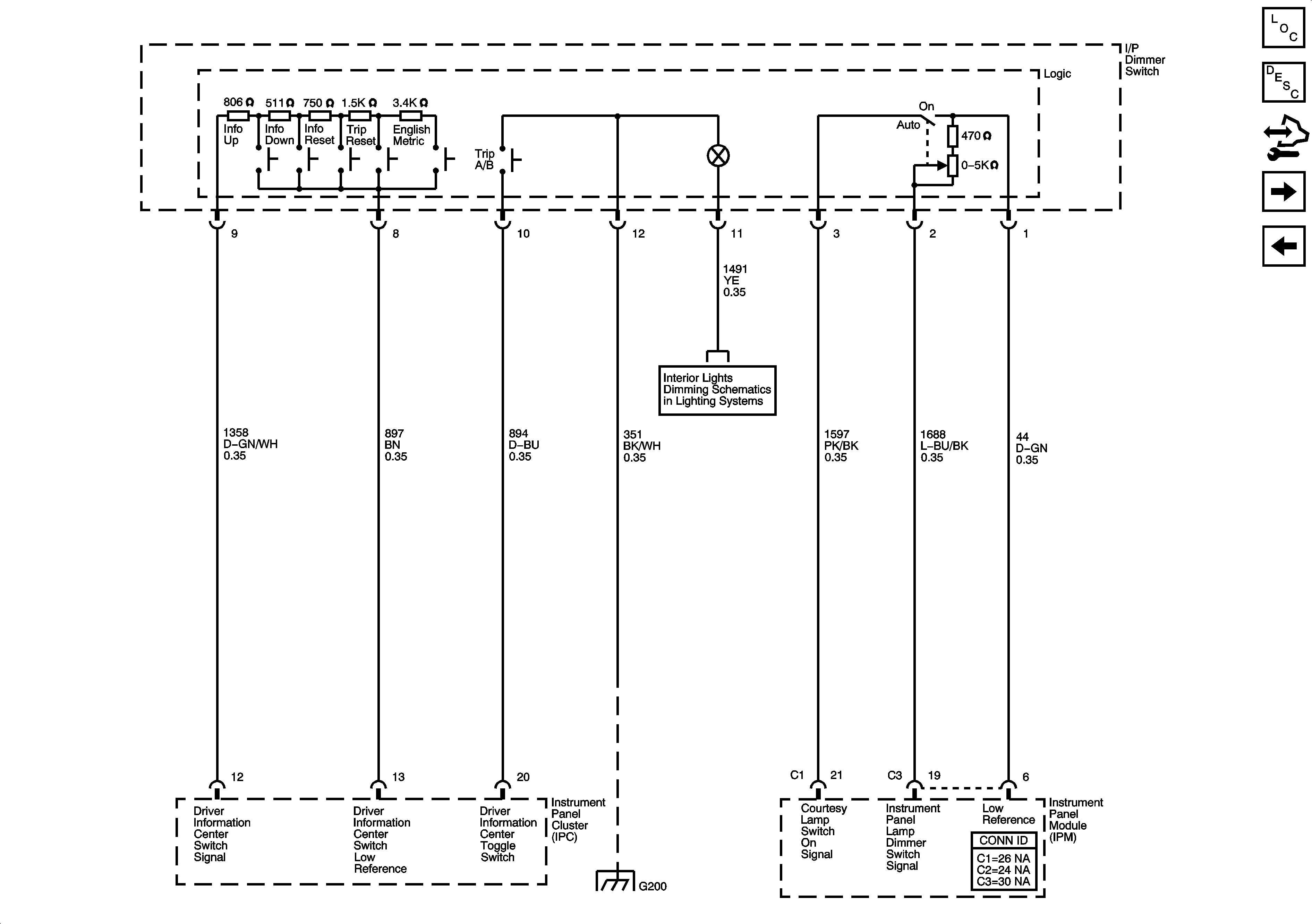
Figure
3:
DIC/Dimmer Switch
Master Electrical Component List
Instrument Cluster Description and Operation
Control Module References
Instrument Panel Cluster Schematic - Engine Oil and Fuel Tank Level
Indicators
Dimming Lamps (1 of 3)
G200 (2 of 2)
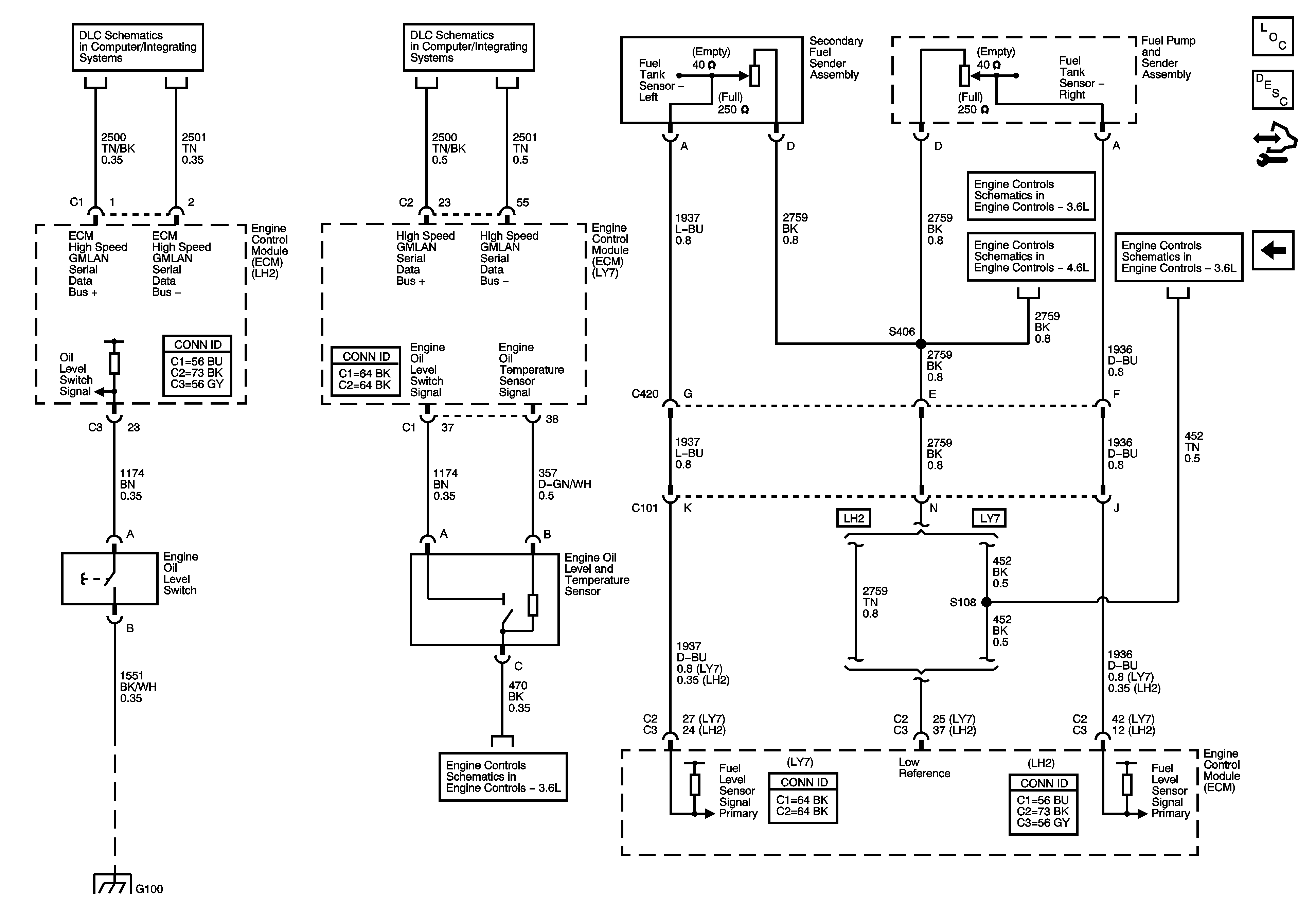
Figure
4:
Master Electrical Component List
Instrument Cluster Description and Operation
Control Module References
DIC/Dimmer Switch
GMLAN High Speed - Domestic w/UE1
Engine Data Sensors - Low Reference Bus
Engine Data Sensors, 5 Volt and Low References
Engine Data Sensors - Low Reference Bus