GM Service Manual Online
For 1990-2009 cars only
Figure 1:

ECM Power, Ground, Serial Data, and MIL
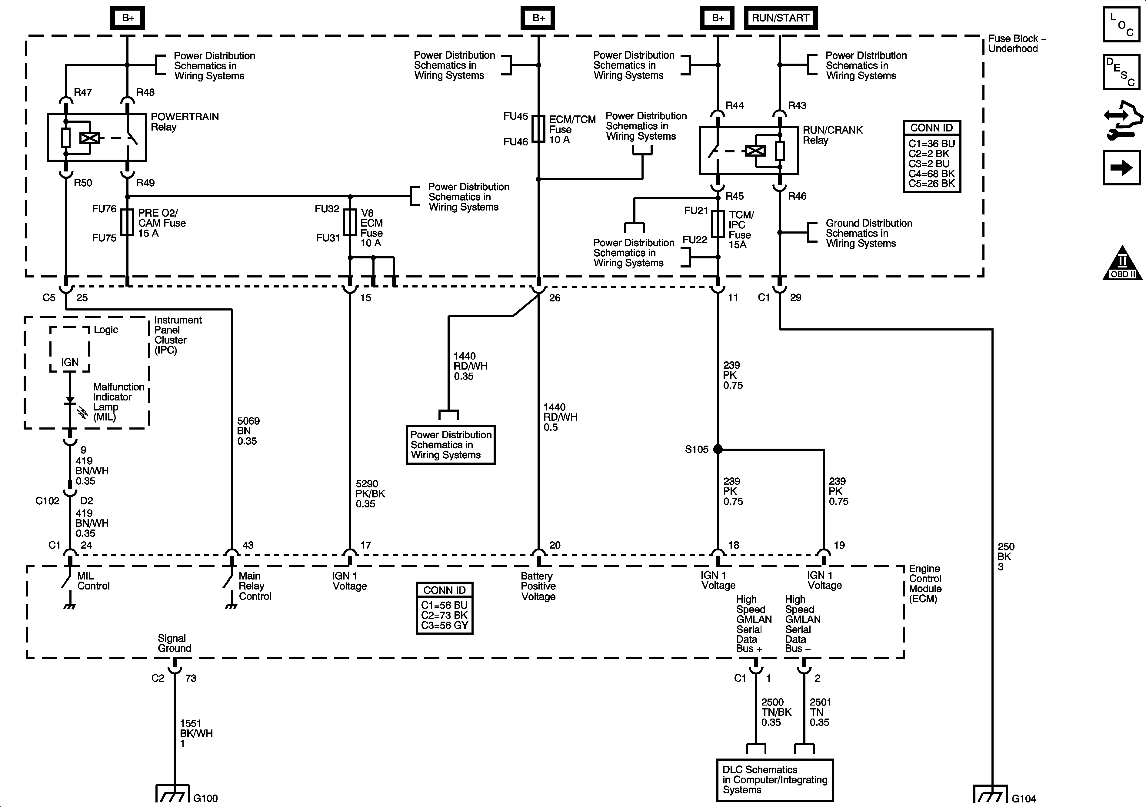

Object Number: 1349788  Size: FS
Master Electrical Component List
Engine Control Module Description
Control Module References
Engine Data Sensors, 5 Volt and Low References
Engine Controls Schematic Icons
Fuse Block Underhood Bussing
Fuse Block-Underhood Fuses/Relay: IPM/ALDL, Auto Headlamp Dimming, CCP, ECM/TCM, WPR MOD, WPR SW/VICS and Rain Sensor/HDLP Wash Fuses. Accessory Relay
Fuse Block-Underhood: Starter IGN 1 Relays; Starter, Starter Relay, CCP, TCM/IPM/ECM, MAF, ABS and Washer Nozzle/ACC Fuses
Fuse Block Right Rear: LT Turn Signal, RIM(1), Rear Fog Lamp, FT Passenger Door Module, Heated Steering Column, IGN 1, RIM(2) and Airbag Fuses; Rear Fog Lamp and IGN 1 Relays
G104 (1 of 2)
Fuse Block-Underhood Fuses/Relay: IPM/ALDL, Auto Headlamp Dimming, CCP, ECM/TCM, WPR MOD, WPR SW/VICS and Rain Sensor/HDLP Wash Fuses. Accessory Relay
G100 (LH2)
G104 (1 of 2)
Figure 2:

Engine Data Sensors - 5-Volt and Low Reference
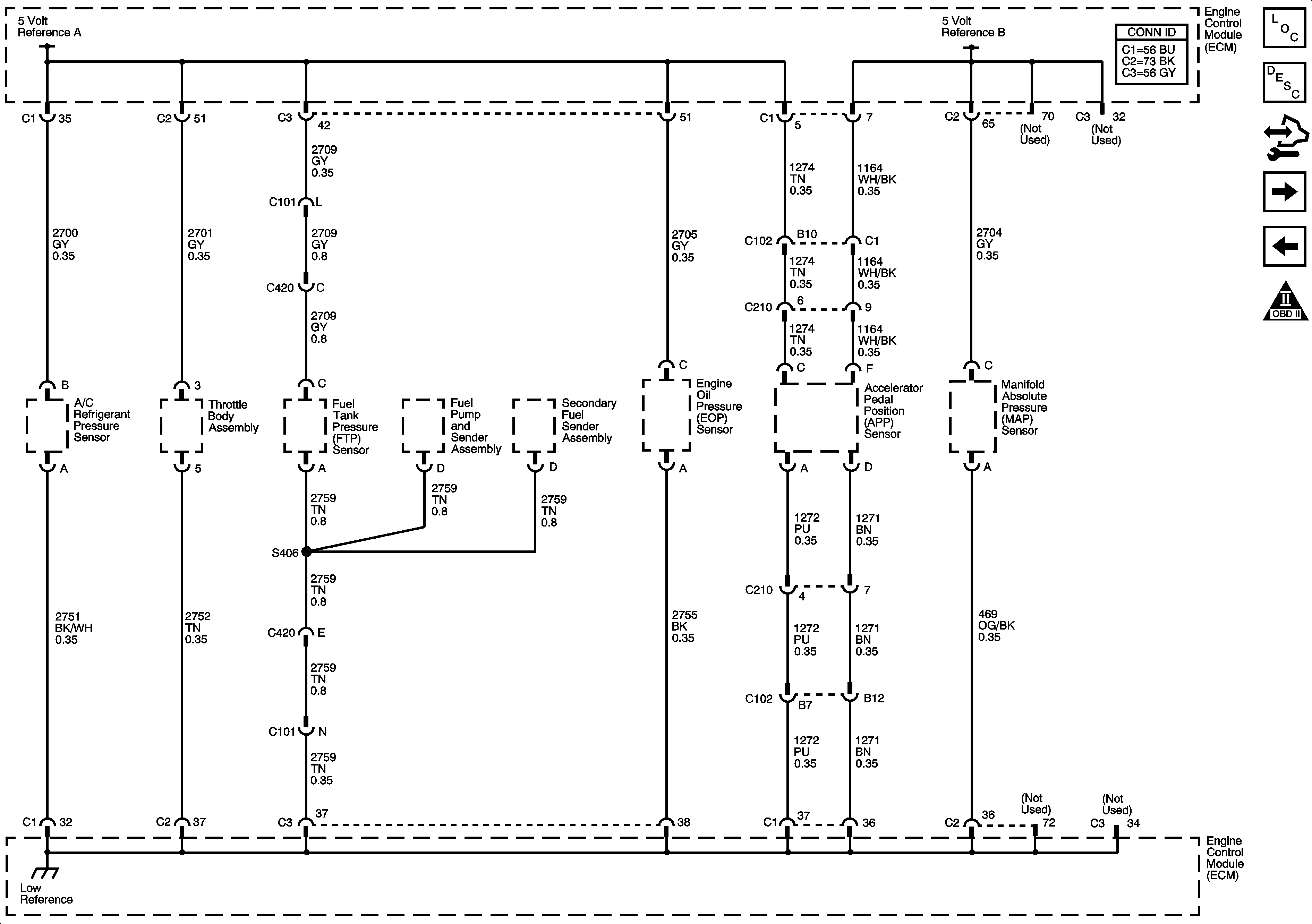

Object Number: 1349780  Size: FS
Master Electrical Component List
Engine Control Module Description
Control Module References
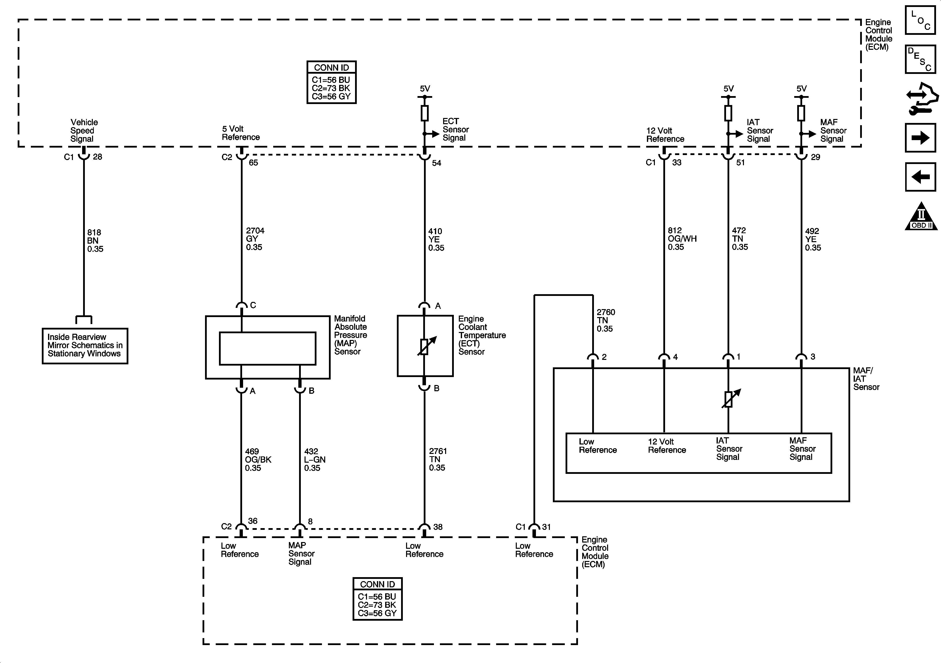
Engine Data Sensors - Pressure, Temperature, MAF, VSS
ECM Power, Ground, DLC and MIL
Engine Controls Schematic Icons
Figure 3:

Engine Data Sensors - Pressure, Temperature, MAF, VSS


Object Number: 1349763  Size: FS
Master Electrical Component List
Air Intake System Description
Control Module References
Engine Data Sensors - Oxygen Sensors
Engine Data Sensors, 5 Volt and Low References
Engine Controls Schematic Icons
Automatic Headlamp Dimming Signals, VSS (TT6)
Figure 4:

Engine Data Sensors - Oxygen Sensors


Object Number: 1349759  Size: FS
Master Electrical Component List
Fuel System Description
Control Module References
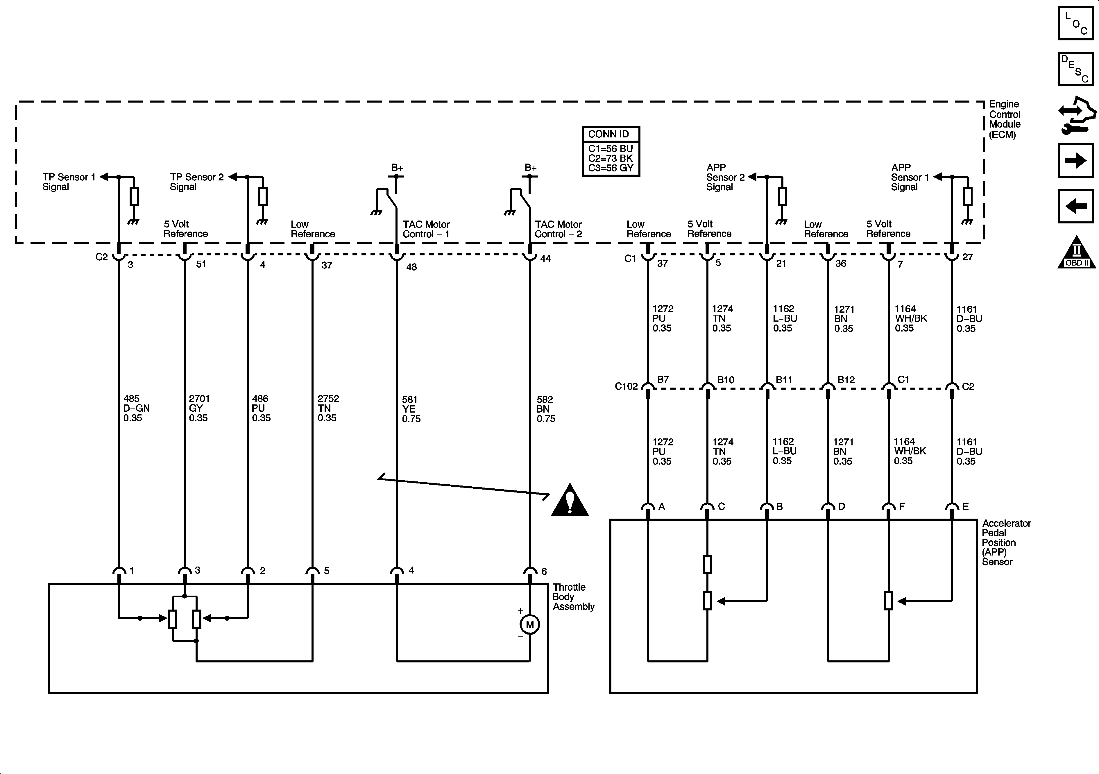
Engine Data Sensors - Electronic Throttle Controls
Engine Data Sensors - Pressure, Temperature, MAF, VSS
Engine Controls Schematic Icons
Fuse Block Underhood Bussing
Figure 5:

Engine Data Sensors - Electronic Throttle Controls


Object Number: 1349793  Size: FS
Master Electrical Component List
Throttle Actuator Control (TAC) System Description
Control Module References
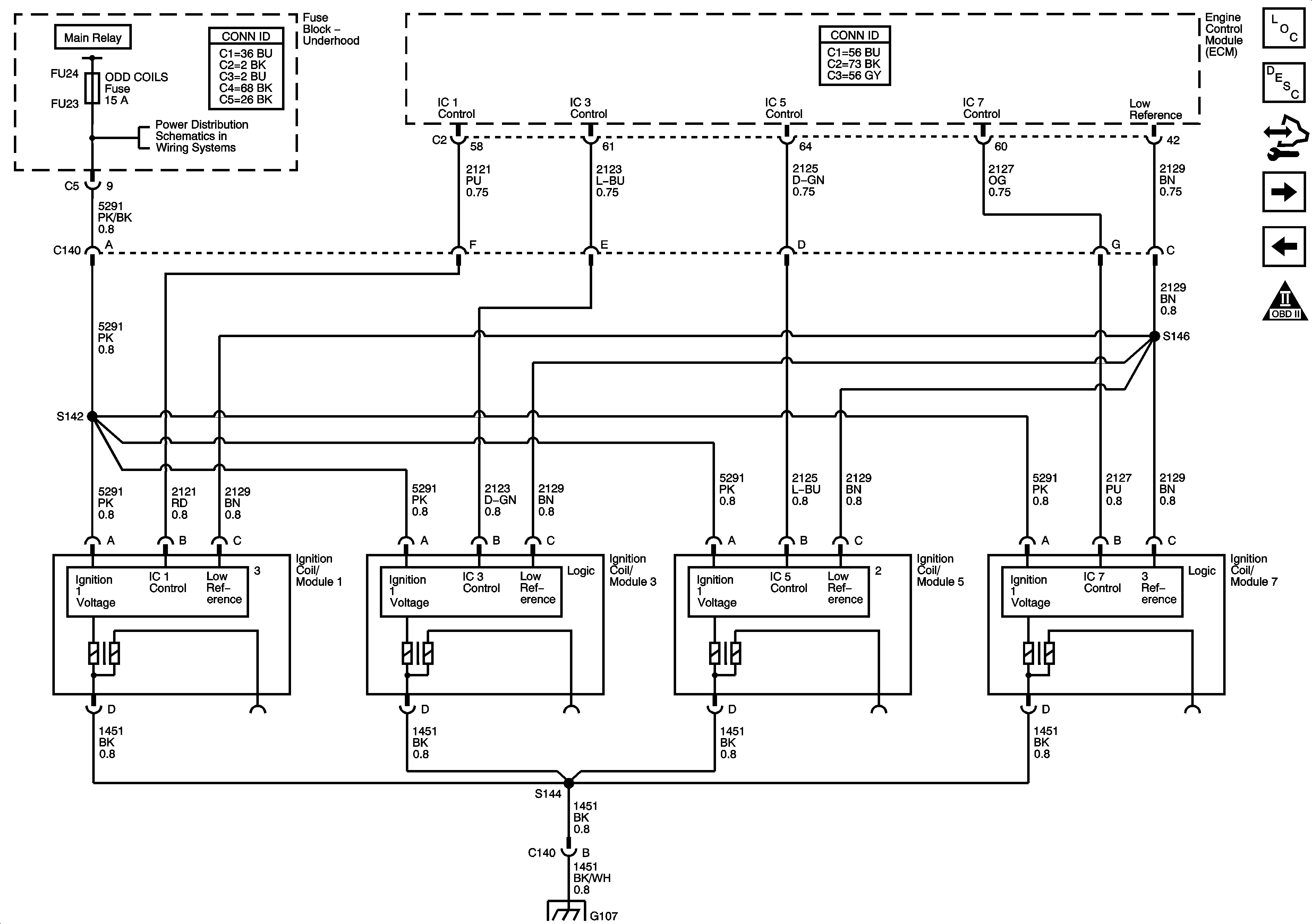
Igniton Controls - Ignition System Bank 1
Engine Data Sensors - Oxygen Sensors
Engine Controls Schematic Icons
Figure 6:

Ignition Controls - Ignition System Bank 1

Object Number: 1349784  Size: FS
Master Electrical Component List
Electronic Ignition (EI) System Description
Control Module References
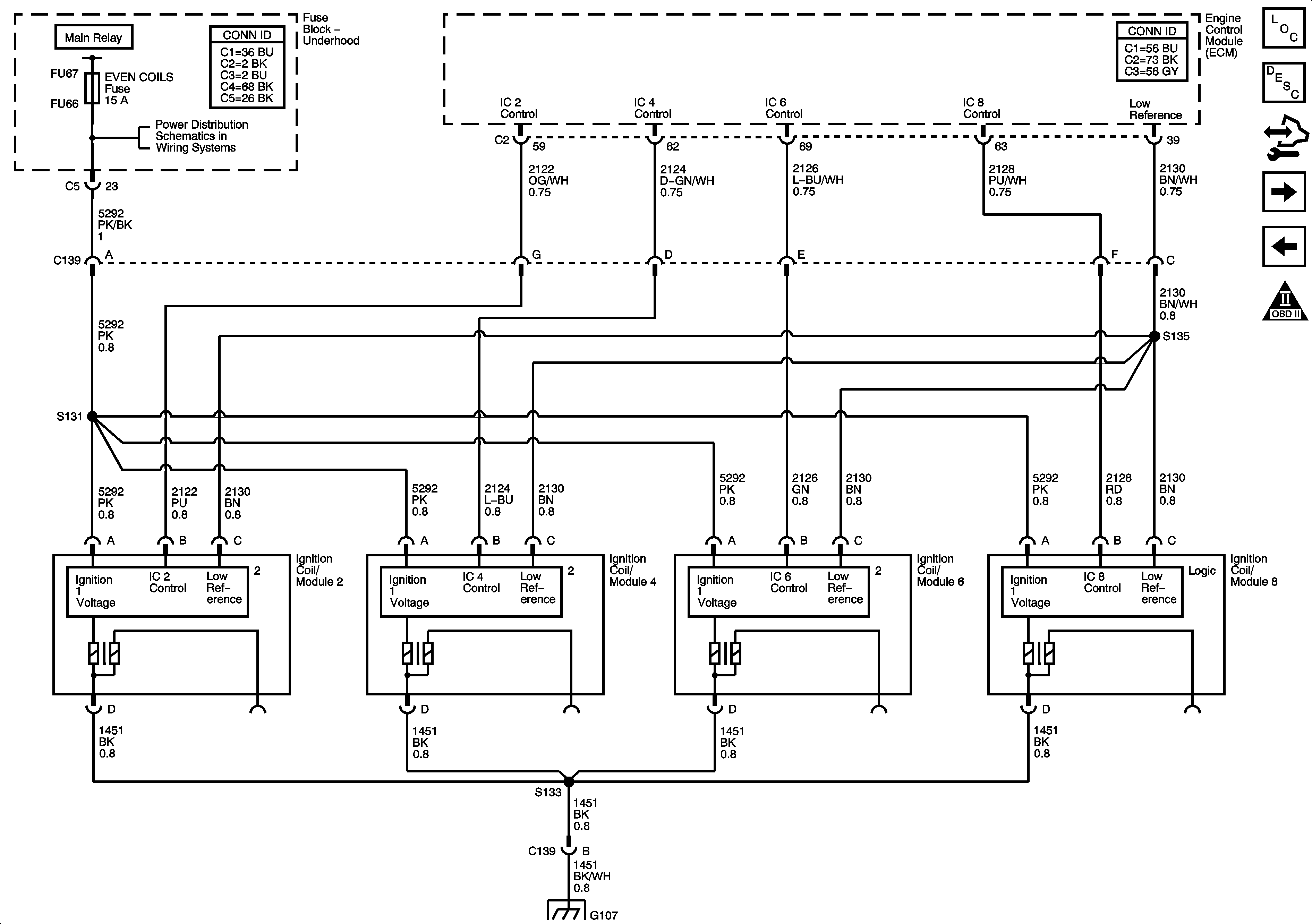
Ignition Controls - Ignition System Bank 2
Engine Data Sensors - Electronic Throttle Controls
Engine Controls Schematic Icons
Fuse Block Underhood: Odd INJ/COILS, Even INJ/COILS and POST 02 Fuses
G107 (LH2), G113 (LY7)
Figure 7:

Ignition Controls - Ignition System Bank 2


Object Number: 1349754  Size: FS
Master Electrical Component List
Electronic Ignition (EI) System Description
Control Module References
Camshaft Position (CMP) Sensors and Actuators
Igniton Controls - Ignition System Bank 1
Engine Controls Schematic Icons
Fuse Block Underhood: Odd INJ/COILS, Even INJ/COILS and POST 02 Fuses
G107 (LH2), G113 (LY7)
Figure 8:

Ignition Controls - CMP Sensors and Solenoids
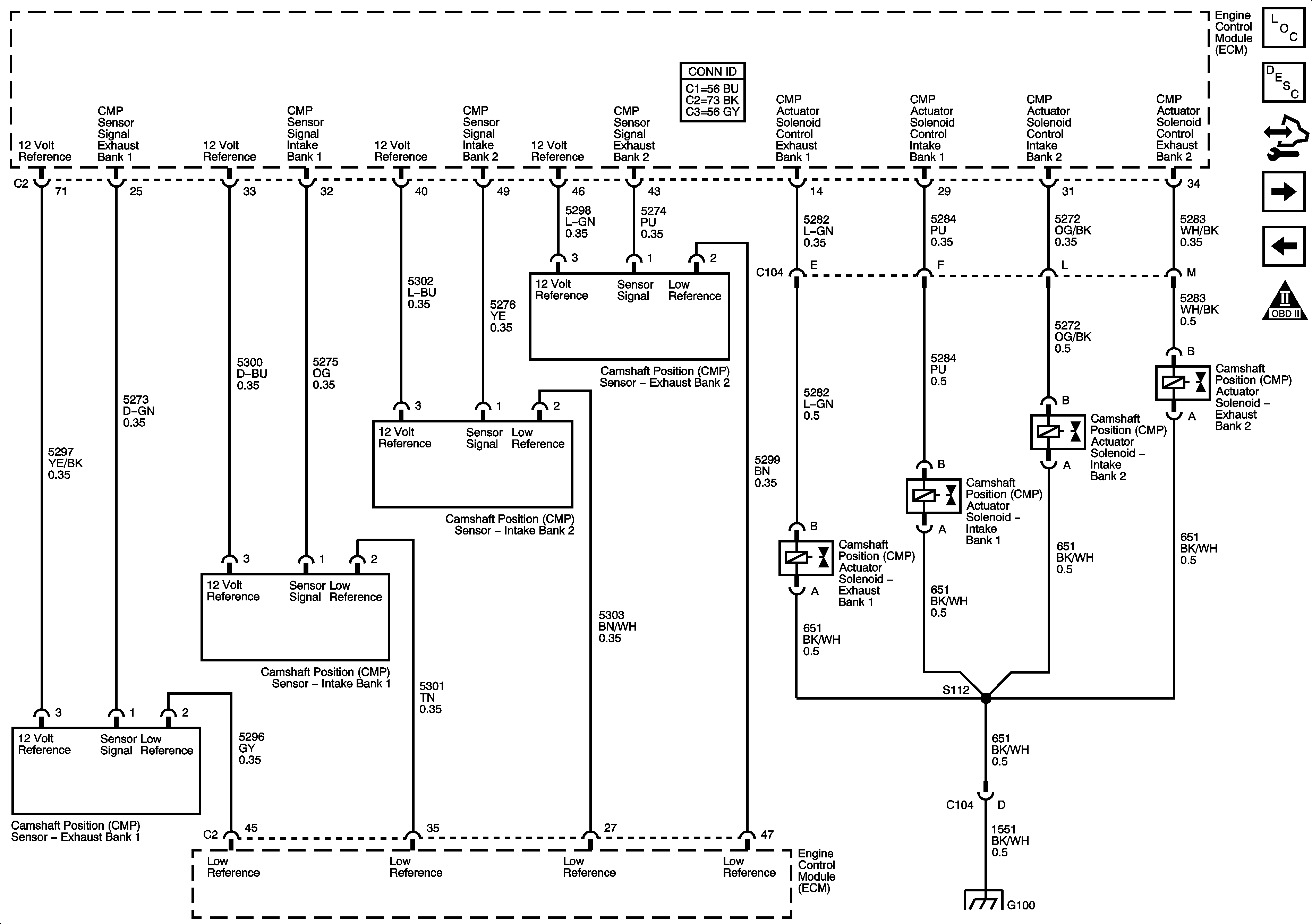

Object Number: 1349786  Size: FS
Master Electrical Component List
Camshaft Actuator System Description
Control Module References
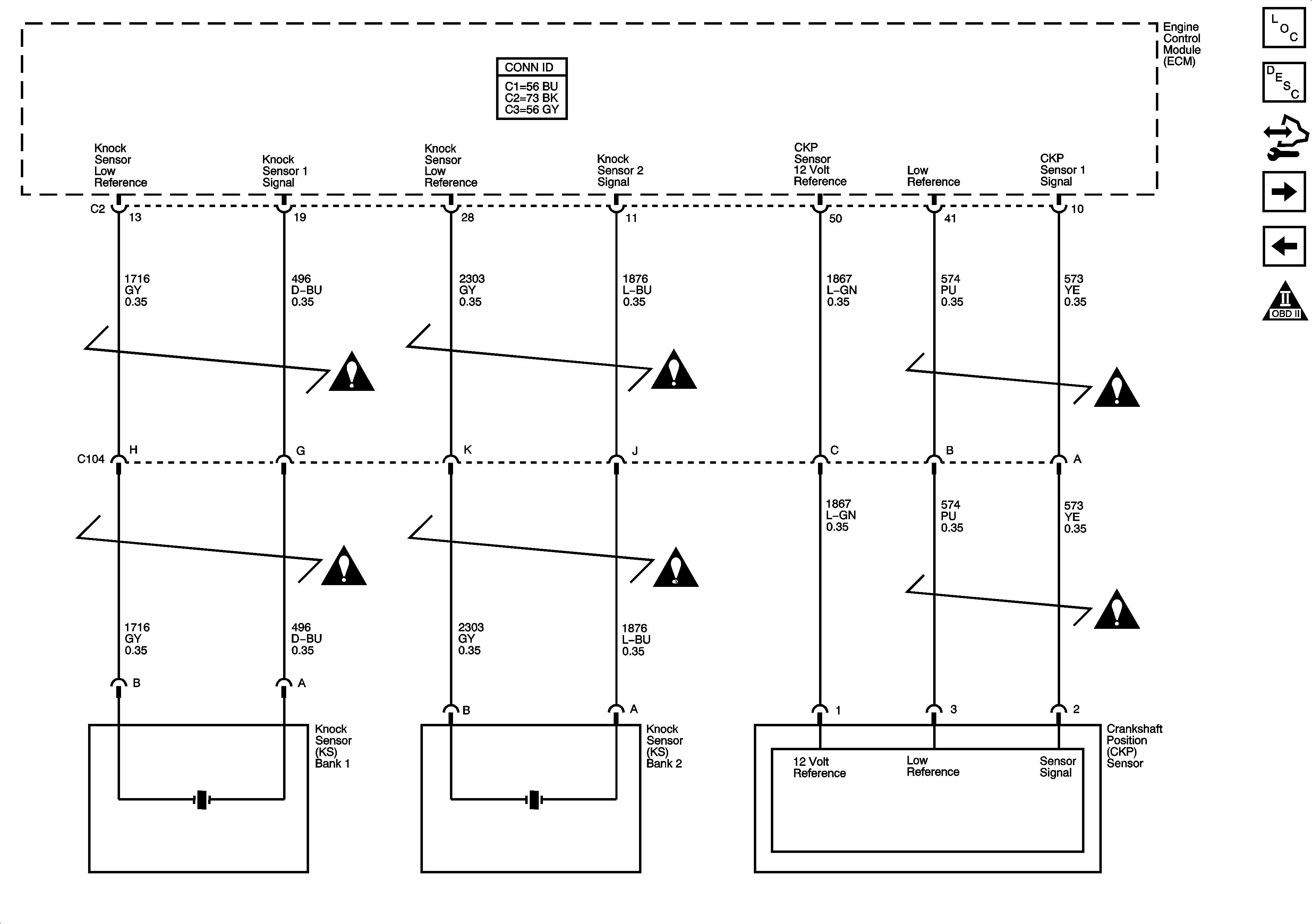
Ignition Controls - Crankshaft Position (CKP) Sensor and Knock Sensors
Ignition Controls - Ignition System Bank 2
Engine Controls Schematic Icons
G100 (LH2)
Figure 9:

Crankshaft Position (CKP) Sensor and Knock Sensors


Object Number: 1349792  Size: FS
Master Electrical Component List
Knock Sensor (KS) System Description
Control Module References
Fuel Controls - Injectors and Pump
Camshaft Position (CMP) Sensors and Actuators
Engine Controls Schematic Icons
Figure 10:

Fuel Controls - Injectors and Pump


Object Number: 1349734  Size: FS
Master Electrical Component List
Fuel System Description
Control Module References
Fuel Controls - EVAP and Fuel Tank Pressure (FTP) Sensor
Ignition Controls - Crankshaft Position (CKP) Sensor and Knock Sensors
Engine Controls Schematic Icons
Fuse Block Underhood: Odd INJ/COILS, Even INJ/COILS and POST 02 Fuses
Fuse Block Underhood Bussing
G401 (1 of 2)
G401 (1 of 2)
Instrument Panel Cluster Schematic - Engine Oil and Fuel Tank Level
Figure 11:

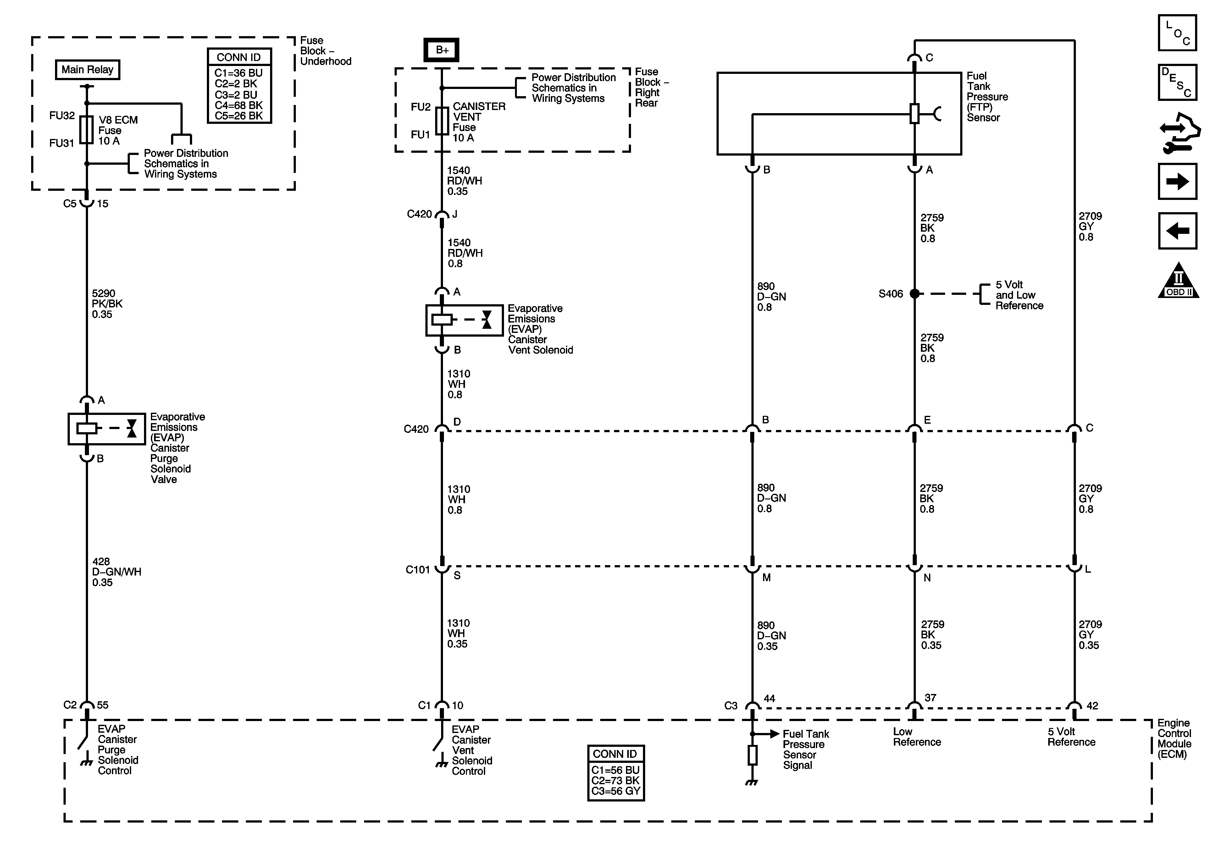
Fuel Controls - EVAP and Fuel Tank Pressure (FTP) Sensor


Object Number: 1349791  Size: FS
Master Electrical Component List
Evaporative Emission Control System Description
Control Module References
Controlled/Monitored Subsystem References
Fuel Controls - Injectors and Pump
Engine Controls Schematic Icons
Fuse Block Underhood LO SPD FAN, HI SPD FAN, V8 ECM, PRE 02/CAM and HFV6 ECM Fuses; Main, LO SPD, HI SPD and S/P FAN Relays
Fuse Block - Right Rear Bussing
Engine Data Sensors, 5 Volt and Low References
Figure 12:

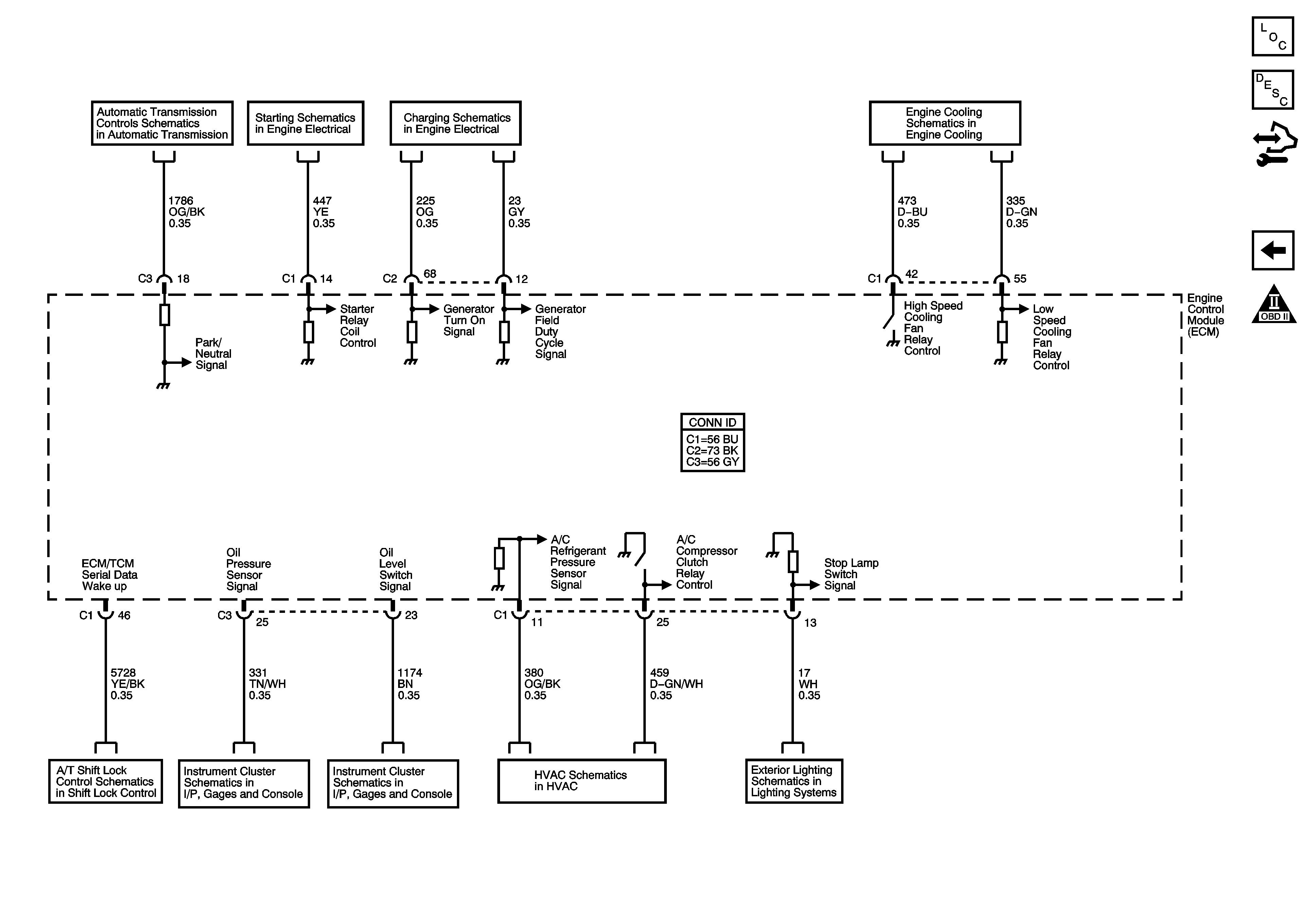
Controlled/Monitored Subsystem References


Object Number: 1349795  Size: FS
Master Electrical Component List
Engine Control Module Description
Control Module References
Fuel Controls - EVAP and Fuel Tank Pressure (FTP) Sensor
Engine Controls Schematic Icons
TCM Power, Grounds and DLC
Starting System - LH2
Charging System
Cooling Fans
Shift Lock Control Schematics
Indicators
Instrument Panel Cluster Schematic - Engine Oil and Fuel Tank Level
A/C Refrigerant Pressure Sensor and Compressor Clutch
Backup Lamps, CHMSL - Domestic and Export