For 1990-2009 cars only
Removal Procedure
The automatic adjustment park brake pedal assembly and the front park brake cable are serviced as a unit. The front park brake cable has no threads and is not adjustable.
- Raise and suitably support the vehicle. Refer to Lifting and Jacking the Vehicle in General Information.
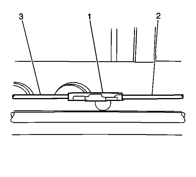
- Pull down on the intermediate park brake cable near the park brake connector (2).
- Remove the front park brake cable (3) from the park brake cable connector (1).
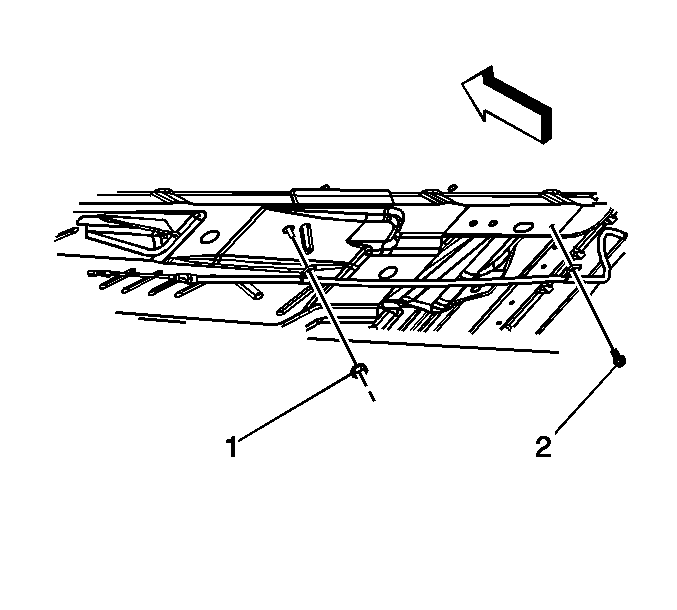
- Remove the park brake cable guide bolt (2).
- Remove the park brake cable guide nut (1).
- Disconnect the park brake cable retainer from the floor pan by compressing the retaining tabs.
- Lower the vehicle.
- Remove the left closeout/insulator panel to access the park brake lever assembly. Refer to Instrument Panel Insulator Panel Replacement - Left Side in Instrument Panel, Gages, and Console.
- Remove the left knee bolster. Refer to Knee Bolster Replacement in Instrument Panel, Gages, and Console.
- Remove the left instrument panel end cap. Refer to Instrument Panel Outer Trim Cover Replacement - Left Side in Instrument Panel, Gages, and Console.
- Remove the left front carpet retainer. Refer to Front Carpet Retainer Replacement in Interior Trim.
- Pull the carpet back in order to expose park brake cable.
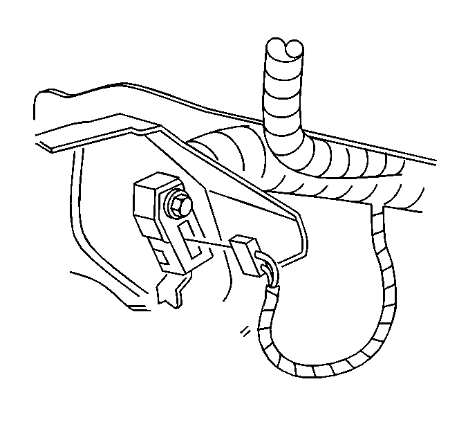
- Disconnect the electrical connector from the park brake warning lamp switch.
- Remove the park brake warning lamp switch wiring harness retainer from the park brake pedal assembly and position the harness out of the way.
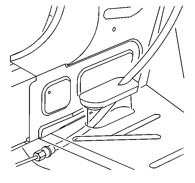
- Remove the grommet from the floor pan.
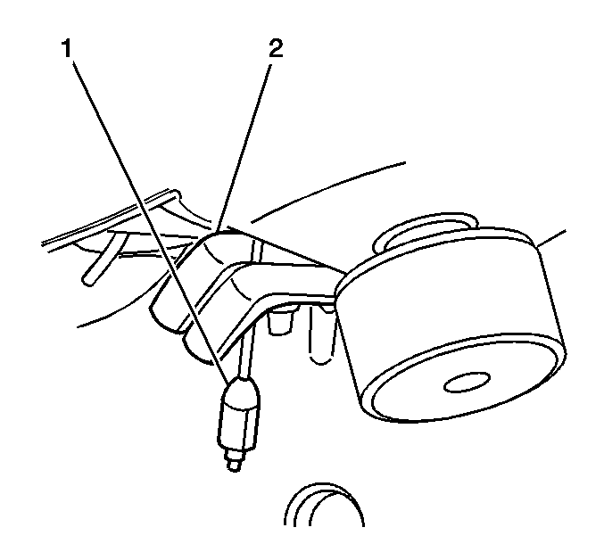
- Disconnect the park brake release cable (1) from the park brake pedal assembly release lever (2).
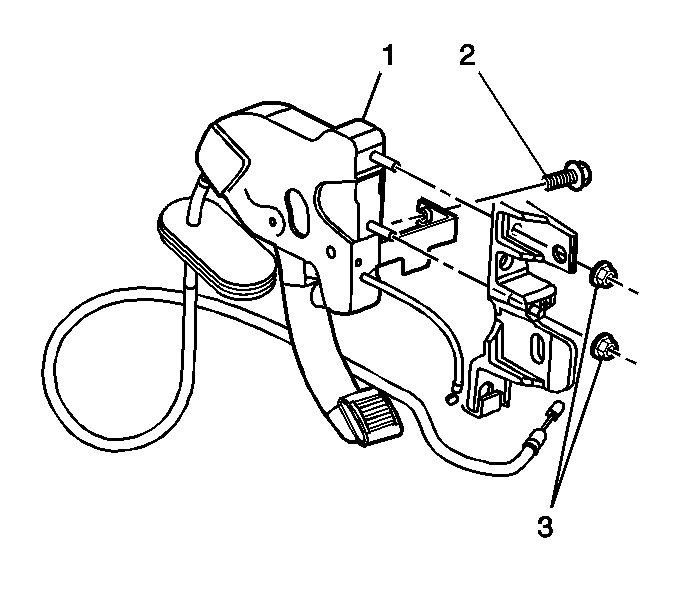
- Remove the park brake pedal assembly (1) attaching nuts (3).
- Remove the park brake pedal assembly (1) attaching bolt (2).
- Remove the park brake pedal and cable assembly (1) from the vehicle.
Installation Procedure
- Connect the park brake release cable (1) to the park brake pedal assembly release lever (2).
- Install the park brake pedal and front park brake cable assembly (1) to the mounting bracket.
- Install the park brake pedal assembly attaching nuts (3).
- Install the park brake pedal assembly cross bar mounting bolt (2).
- Install the grommet to the floor pan.
- Connect the electrical connector to the park brake warning lamp switch.
- Install the park brake warning lamp switch wiring harness retainer to the park brake pedal assembly.
- Reposition the carpet.
- Install the left front carpet retainer. Refer to Front Carpet Retainer Replacement in Interior Trim.
- Raise the vehicle. Refer to Lifting and Jacking the Vehicle in General Information.
- Install the park brake cable retainer to the floor pan by pulling the park brake cable retainer into place.
- Connect the front park brake cable (3) to the park brake cable connector (1).
- Lower the vehicle.
- Install the left instrument panel end cap. Refer to Instrument Panel Outer Trim Cover Replacement - Left Side in Instrument Panel, Gages, and Console.
- If a new park brake pedal assembly is being installed, the cable tension set pin has to be removed to set the cable tension.
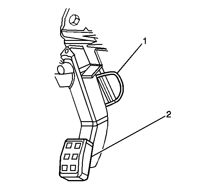
- To set the park brake cable tension, rotate the pin (1) forward then rotate the pin to the left.
- Remove the pin.
- Apply the park brake pedal (2) 3 full cycles to complete the tension set.
- Install the left knee bolster. Refer to Knee Bolster Replacement in Instrument Panel, Gages, and Console.
- Install the left closeout/insulator panel. Refer to Instrument Panel Insulator Panel Replacement - Left Side in Instrument Panel, Gages, and Console.


Notice: Refer to Fastener Notice in the Preface section.
Tighten
Tighten the park brake pedal assembly mounting nuts
to 25 N·m (18 lb ft).
Tighten
Tighten the park brake pedal cross bar mounting
bolt to 10 N·m (88 lb in).


