SMU - Revised Steering Knuckle Replacement Procedure

| Subject: | Revised Steering Knuckle Replacement Procedure |
| Models: | 2005 Cadillac STS |
This bulletin is being issued to revise the Steering Knuckle Replacement procedure in the Front Suspension sub-section of the Service Manual. Please replace the current information in the Service Manual with the following information.
The following information has been updated within SI. If you are using a paper version of this Service Manual, please make a reference to this bulletin on the affected page.
Steering Knuckle Replacement (RWD)
Notice: The ball stud must not rotate during disassembly/reassembly. Hand tools must be used to keep the ball stud from rotating. If air tools are used, and the stud is allowed to rotate, damage to the ball stud may occur.
Notice: Do not free the ball stud by using a pickle fork or a wedge-type tool. Damage to the seal or bushing may result.
Removal Procedure
- Raise and support the vehicle. Refer to Lifting and Jacking the Vehicle.
- Remove the tire and wheel. Refer to Tire and Wheel Removal and Installation.
- Remove the wheel bearing/hub. Refer to Wheel Bearing/Hub Replacement - Front.
- Remove the outer tie rod to steering knuckle. Refer to Rack and Pinion Outer Tie Rod End Replacement.
- Remove the brake hose bracket to steering knuckle retaining bolts.
- Remove the upper control arm ball stud from the steering knuckle. Refer to Shock Module Replacement.
- Remove the lower control arm ball stud from the steering knuckle. Refer to Lower Control Arm Replacement.
- Remove the steering knuckle.
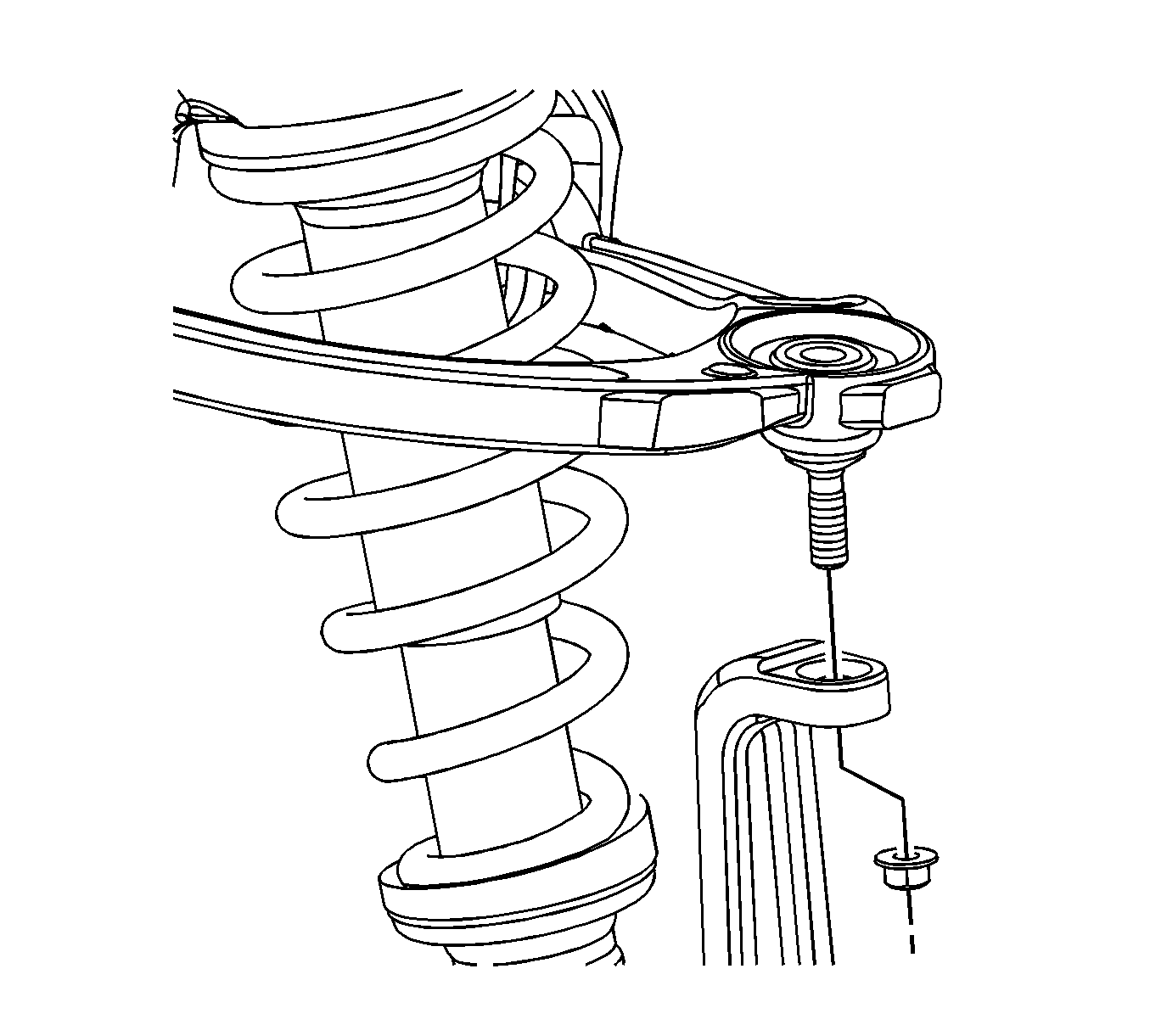
Installation Procedure
- Install the steering knuckle to the lower control arm ball stud. Refer to Lower Control Arm Replacement.
- Install the upper control arm ball stud to the steering knuckle. Refer to Shock Module Replacement.
- Install the brake hose bracket to the steering knuckle retaining bolts.
- Install the outer tie rod to the steering knuckle. Refer to Rack and Pinion Outer Tie Rod End Replacement.
- Install the wheel bearing/hub. Refer to Wheel Bearing/Hub Replacement - Front.
- Install the tire and wheel. Refer to Tire and Wheel Removal and Installation.
- Lower the vehicle.

Notice: Refer to Fastener Notice.
Tighten
Tighten the bolts to 14 N·m (10 lb ft).
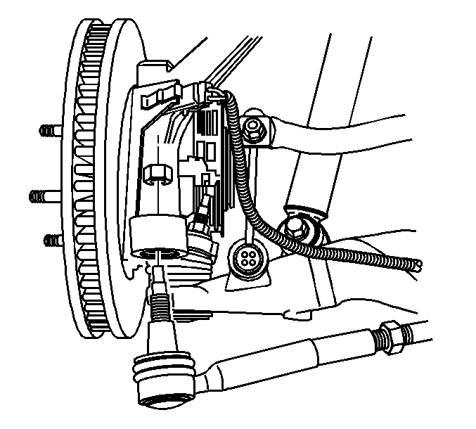
Steering Knuckle Replacement (AWD)
Notice: The ball stud must not rotate during disassembly/reassembly. Hand tools must be used to keep the ball stud from rotating. If air tools are used, and the stud is allowed to rotate, damage to the ball stud may occur.
Notice: Do not free the ball stud by using a pickle fork or a wedge-type tool. Damage to the seal or bushing may result.
Removal Procedure
- Raise and support the vehicle. Refer to Lifting and Jacking the Vehicle.
- Remove the tire and wheel. Refer to Tire and Wheel Removal and Installation.
- Remove the wheel bearing/hub. Refer to Wheel Bearing/Hub Replacement.
- Remove the outer tie rod from the steering knuckle. Refer to Rack and Pinion Outer Tie Rod End Replacement.
- Remove the brake hose bracket to steering knuckle retaining bolts.
- Remove the upper control arm ball stud from the steering knuckle retaining nut. Refer to Shock Module Replacement.
- Remove the lower control arm ball stud from the steering knuckle. Refer to Lower Control Arm Replacement.
- Remove the steering knuckle.
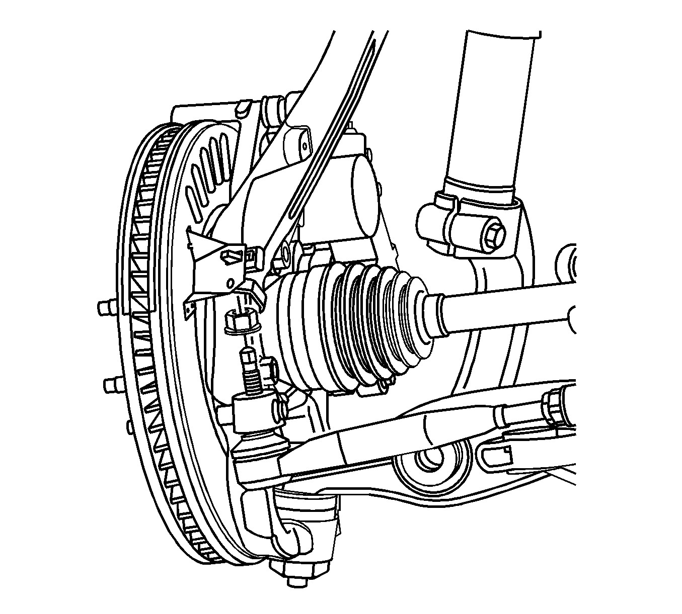
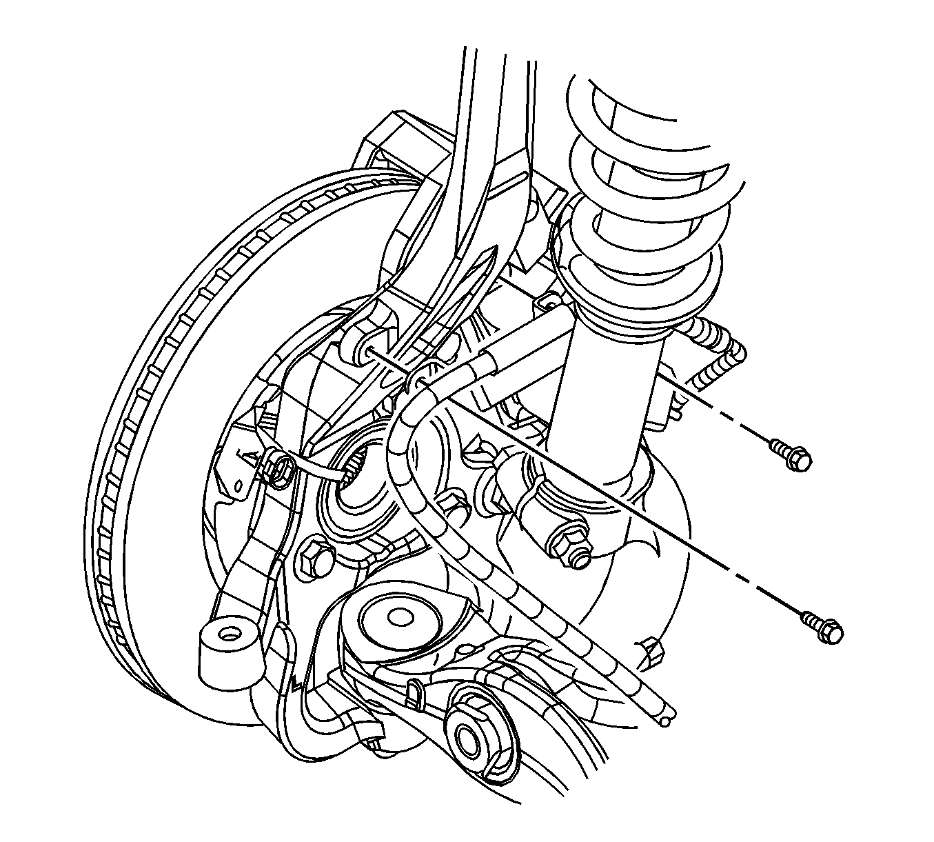

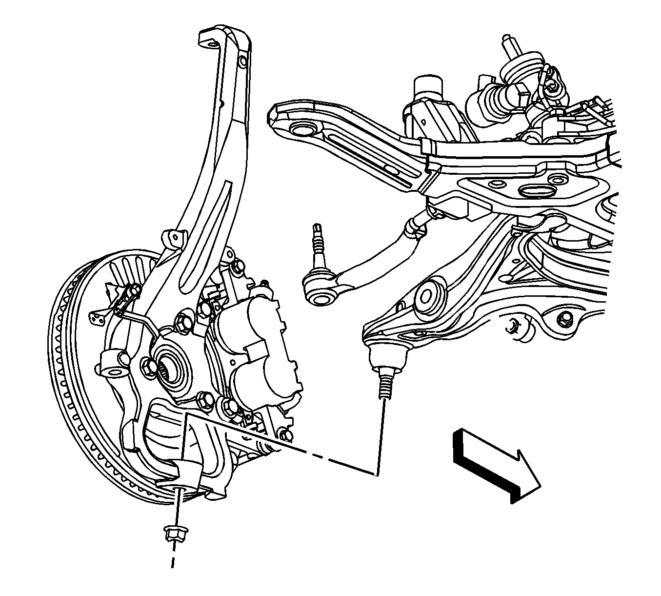
Installation Procedure
- Install the steering knuckle to the lower control arm ball stud.
- Install a new lower control arm ball stud retaining nut. Refer to Lower Control Arm Replacement.
- Install the upper control arm ball stud to the steering knuckle.
- Install a new upper control arm ball stud retaining nut. Refer to Shock Module Replacement.
- Install the brake hose bracket to the steering knuckle retaining bolts.
- Connect the outer tie rod to the steering knuckle. Refer to Rack and Pinion Outer Tie Rod End Replacement.
- Install the wheel bearing/hub. Refer to Wheel Bearing/Hub Replacement - Front.
- Install the tire and wheel. Refer to Tire and Wheel Removal and Installation.
- Lower the vehicle.


Notice: Refer to Fastener Notice.
Tighten
Tighten the bolts to 14 N·m (10 lb ft).

