Water Outlet Replacement LH2
Removal Procedure
- Drain the cooling system. Refer to Cooling System Draining and Filling .
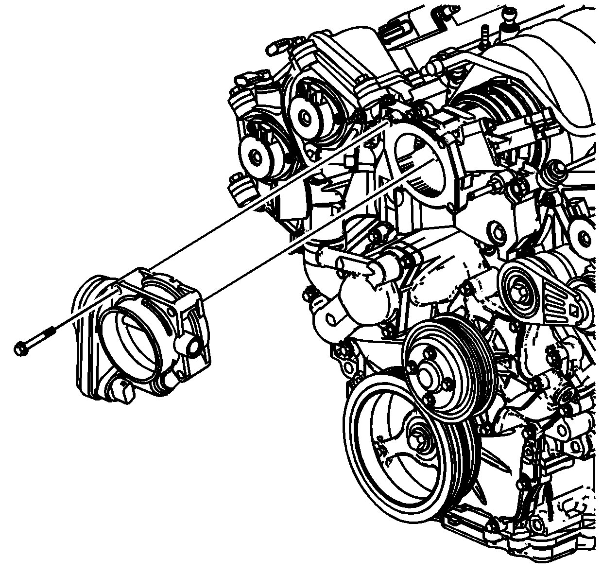
- Remove the throttle body. Refer to Throttle Body Assembly Replacement .
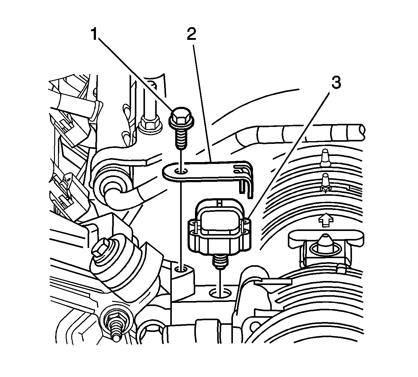
- Remove the manifold absolute pressure (MAP) sensor (3). Refer to Manifold Absolute Pressure Sensor Replacement .
- Disconnect the evaporative emission (EVAP) canister purge solenoid valve hose and electrical connector. Refer to Evaporative Emission Canister Purge Solenoid Valve Replacement .
- Compress the clamps and remove the following hoses from the thermostat and the water housing:
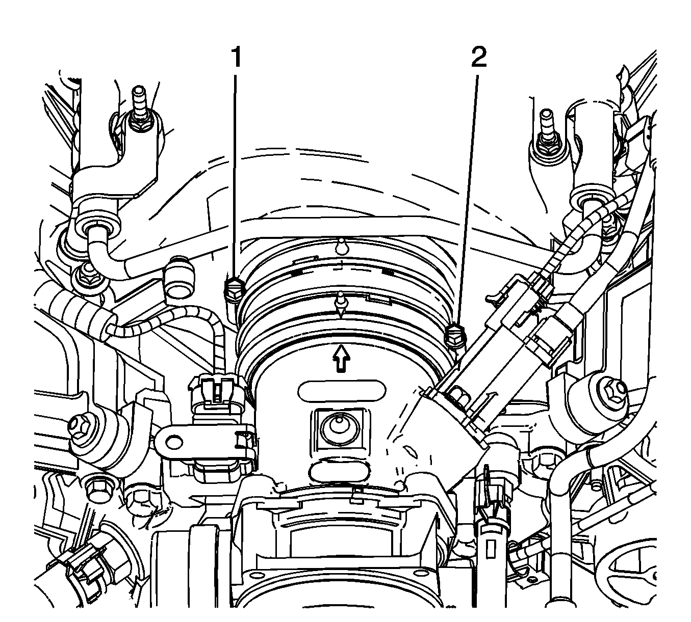
- Loosen the intake manifold duct clamp (1).
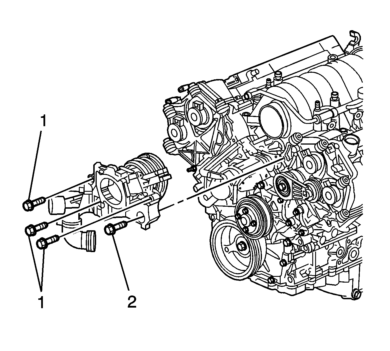
- Remove the bolts (1, 2) securing the water outlet housing to the cylinder heads.
- Remove the water outlet housing from the vehicle.
- Discard the water outlet housing gaskets.
- Clean and inspect the water outlet housing. Refer to Water Outlet Housing Cleaning and Inspection .
- Remove the following components from the water outlet housing if replacement is necessary:
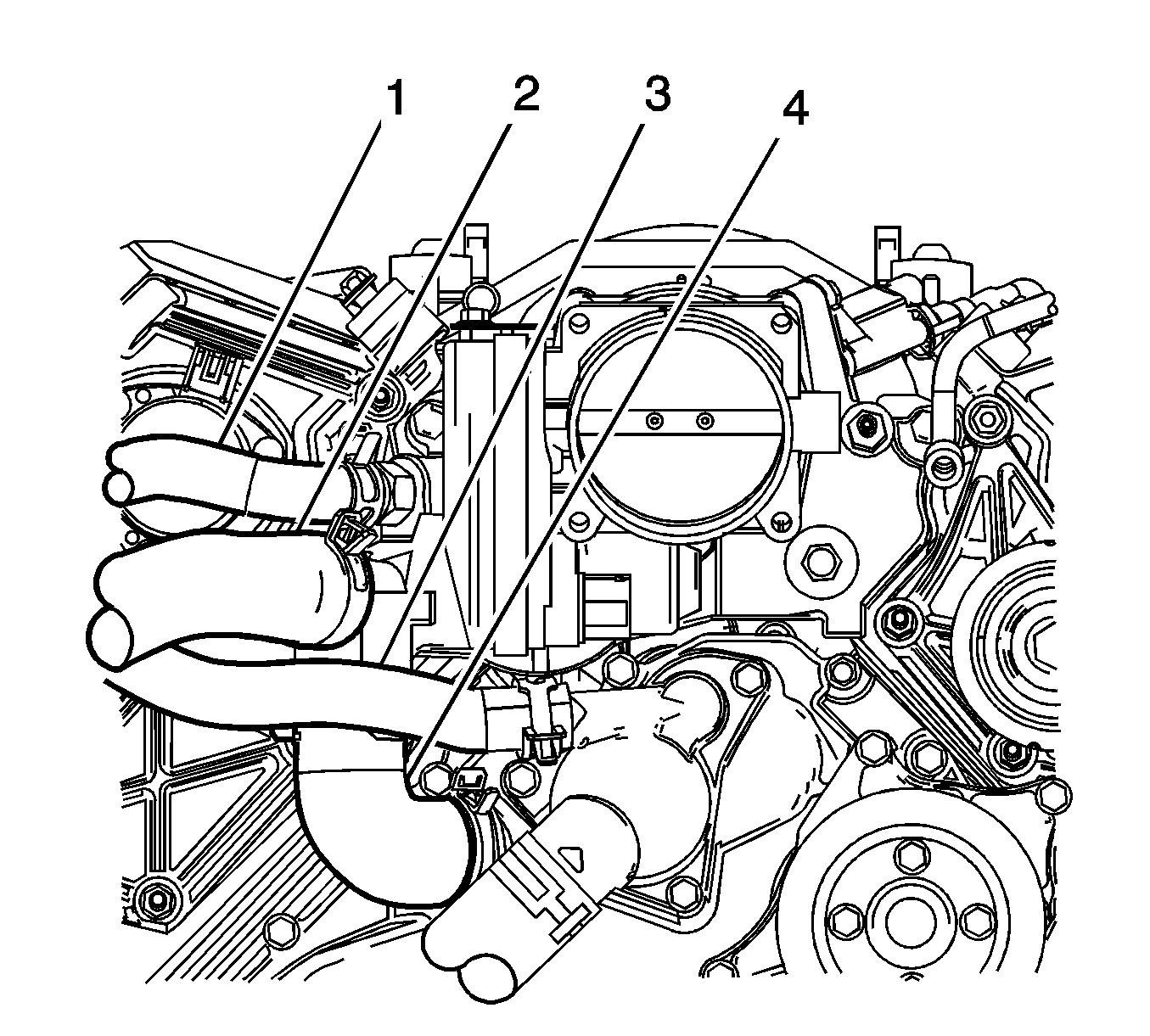
| • | The heater inlet hose (1) |
| • | The radiator inlet hose (2) |
| • | The heater outlet hose (3) |
| • | The bypass hose (4) |
| • | The surge tank inlet hose |
| • | The intake manifold inlet duct and clamp |
| • | The surge tank inlet hose fitting |
| • | The heater inlet hose fitting |
| • | The evaporative emission (EVAP) canister purge solenoid valve--Refer to Evaporative Emission Canister Purge Solenoid Valve Replacement . |
Installation Procedure
- Install the following components to the water outlet housing if previously removed:
- Install NEW water outlet housing gaskets.
- Install the water outlet housing to the vehicle.
- Install the water outlet housing bolts.
- Install the intake manifold duct clamp (1).
- Compress the clamps and install the following hoses to the thermostat and the water housing:
- Connect the evaporative emission (EVAP) canister purge solenoid valve hose and electrical connector. Refer to Evaporative Emission Canister Purge Solenoid Valve Replacement .
- Install the manifold absolute pressure (MAP) sensor (3). Refer to Manifold Absolute Pressure Sensor Replacement .
- Install the throttle body. Refer to Throttle Body Assembly Replacement .
- Fill the cooling system. Refer to Cooling System Draining and Filling .
Notice: Refer to Fastener Notice in the Preface section.

| • | The intake manifold inlet duct and clamp |
Tighten
Tighten the manifold inlet duct clamp to 6 N·m (53 lb in).
| • | The surge tank inlet hose fitting |
Tighten
Tighten the surge tank inlet hose fitting to 18 N·m (13 lb ft).
| • | The heater inlet hose fitting |
Tighten
Tighten the heater inlet hose fitting to 20 N·m (15 lb ft).
| • | The (EVAP) canister purge solenoid valve |
Tighten
Tighten the purge solenoid valve bolt to 12 N·m (106 lb in).
Important: The water outlet housing uses two different size bolts. Bolt (2) is approximately 10 mm longer than the other 3 bolts (1).
Tighten
Tighten the water outlet housing bolts to 25 N·m (18 lb ft).

Tighten
Tighten the intake manifold inlet duct clamp to 6 N·m (53 lb in).

| • | The heater inlet hose (1) |
| • | The radiator inlet hose (2) |
| • | The heater outlet hose (3) |
| • | The bypass hose (4) |
| • | The surge tank inlet hose |


Water Outlet Replacement LY7, LLT
Removal Procedure
- Partially drain the cooling system. Refer to Cooling System Draining and Filling .
- For the LLT engine, remove the throttle body. Refer to Throttle Body Assembly Replacement .
- Remove the radiator hose from the water outlet. Refer to Radiator Inlet Hose Replacement .
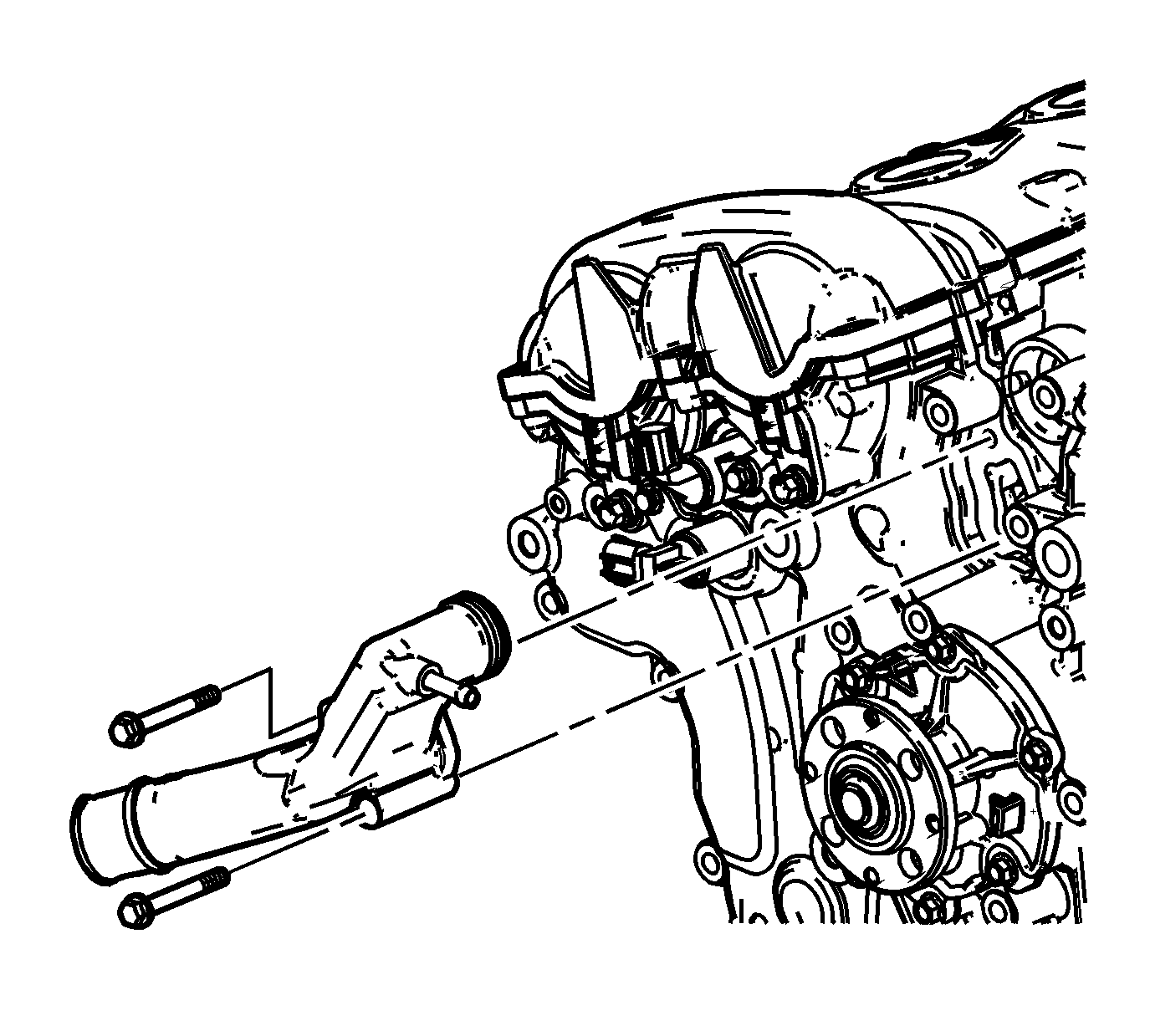
- Remove the water outlet housing bolts.
- Remove the water outlet.
- Remove and discard the water outlet seals.
- Clean the water outlet housing sealing surfaces.
Installation Procedure
- Install NEW water outlet housing seals.
- Install the water outlet.
- Install the water outlet bolts.
- Install the radiator hose to the water outlet. Refer to Radiator Inlet Hose Replacement .
- For the LLT engine, install the throttle body. Refer to Throttle Body Assembly Replacement .
- Fill the cooling system. Refer to Cooling System Draining and Filling .

Notice: Refer to Fastener Notice in the Preface section.
Tighten
Tighten the water outlet housing bolts to 10 N·m(89 lb in).
Water Outlet Replacement LC3
Removal Procedure
- Drain the engine cooling system. Refer to Cooling System Draining and Filling .
- Drain the charge air cooling system. Refer to Charge Air Cooling System Draining and Filling .
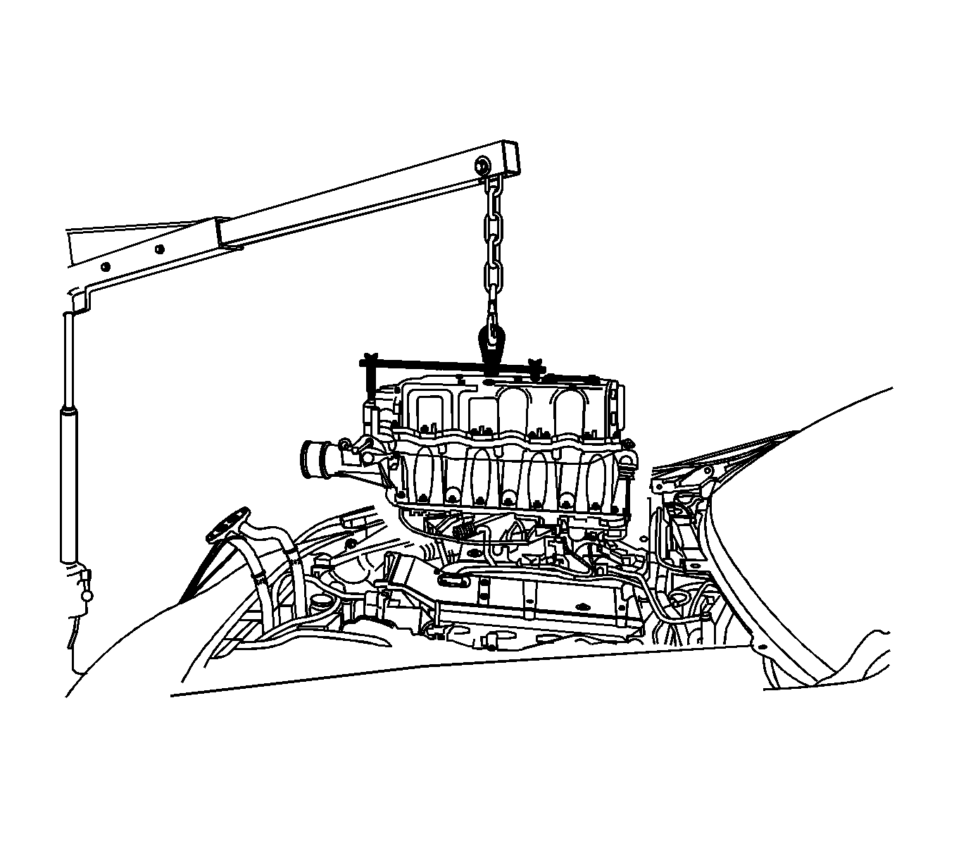
- Remove the supercharger assembly. Refer to Supercharger Replacement .
- Remove the supercharger belt tensioner. Refer to Drive Belt Tensioner Replacement - Supercharger .
- Remove the inboard supercharger idler pulley. Refer to Belt Idler Pulley Replacement - Supercharger .
- Remove the two coolant hoses from the water outlet housing. Refer to Radiator Surge Tank Inlet Hose/Pipe Replacement .
- Remove the radiator hose from the water outlet housing. Refer to Radiator Inlet Hose Replacement .
- Reposition the lower clamp on the bypass hose.
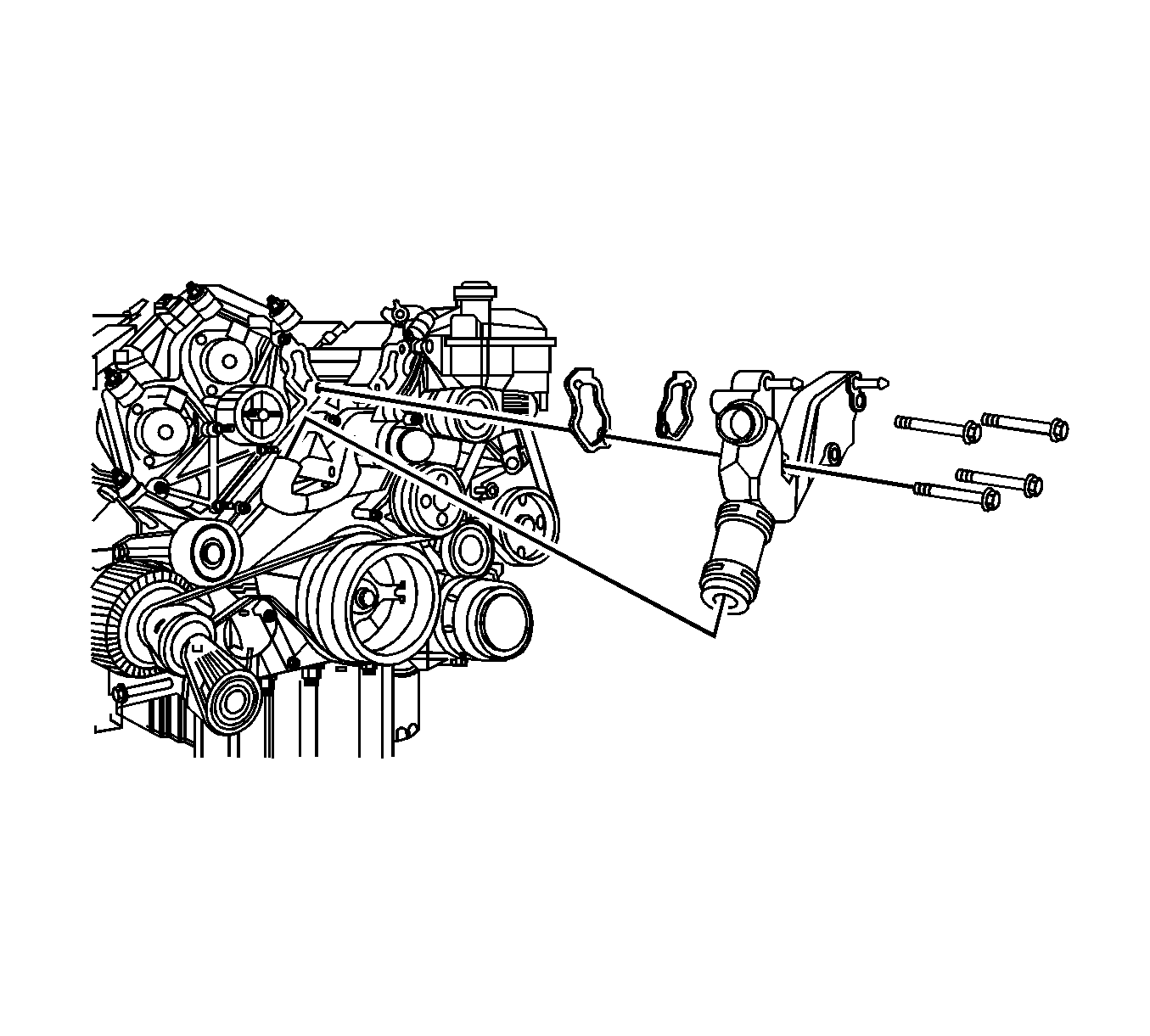
- Remove the bolts securing the water outlet housing to the cylinder heads.
- Remove the water outlet housing along with the bypass hose from the engine.
- Discard the water outlet housing gaskets.
- Disassemble the water outlet housing if necessary. Refer to Water Outlet Housing Disassemble
- Clean and inspect the water outlet housing. Refer to Water Outlet Housing Cleaning and Inspection .
Installation Procedure
- Assemble the water outlet housing if necessary. Refer to Water Outlet Housing Assemble .
- Install NEW water outlet housing gaskets.
- Install the water outlet housing with bypass hose to the vehicle.
- Install the water outlet housing bolts.
- Install the bypass hose clamp in the proper position.
- Install the radiator hose to the water outlet housing. Refer to Radiator Inlet Hose Replacement .
- Install the two coolant hoses to the water outlet housing. Refer to Radiator Surge Tank Inlet Hose/Pipe Replacement .
- Install the supercharger idler pulley. Refer to Belt Idler Pulley Replacement - Supercharger .
- Install the supercharger belt tensioner. Refer to Drive Belt Tensioner Replacement - Supercharger .
- Install the supercharger assembly. Refer to Supercharger Replacement .
- Fill the charge air cooling system with coolant. Refer to Charge Air Cooling System Draining and Filling .
- Fill the engine cooling system with coolant. Refer to Cooling System Draining and Filling .
- Check the engine cooling system for leaks.
- Check the charge air cooling system for leaks.

Notice: Refer to Fastener Notice in the Preface section.
Tighten
Tighten the water outlet housing bolts to 25 N·m (18 lb ft).

