GM Service Manual Online
For 1990-2009 cars only
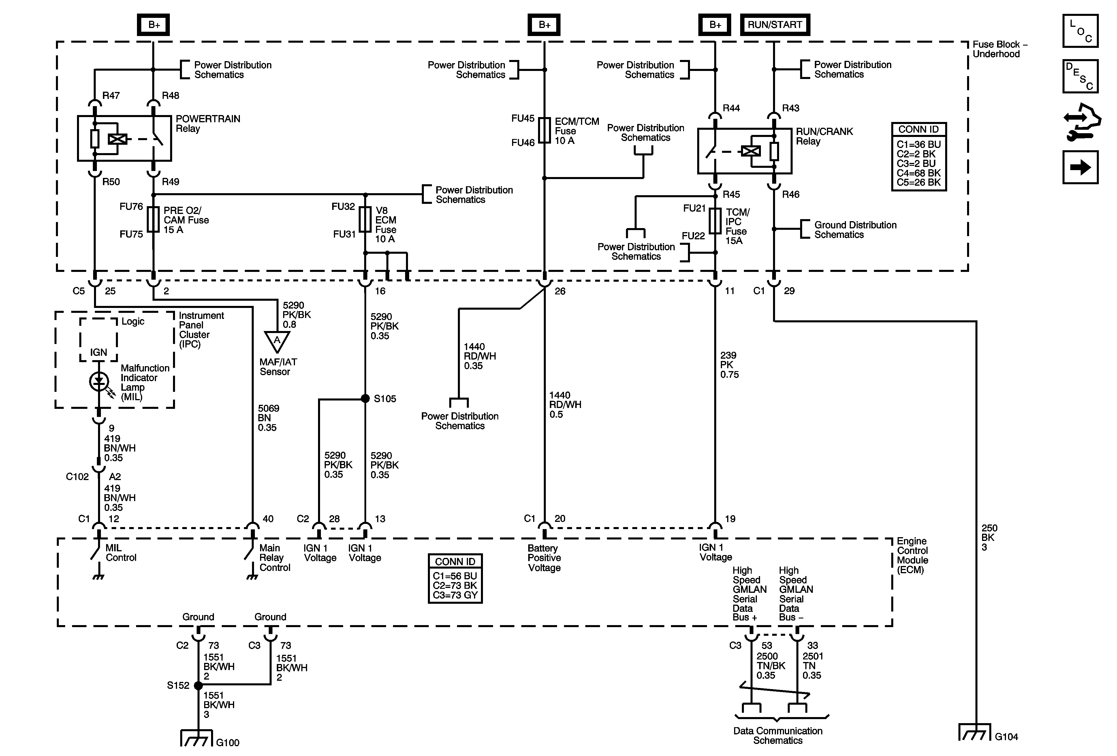
Figure 1:

ECM Power, Ground, Serial Data, and MIL

Object Number: 1821910  Size: FS
Master Electrical Component List
Engine Control Module Description
Control Module References
Engine Data Sensors - 5-Volt and Low References 1 of 2
Fuse Block Underhood Wiring Bussing
Fuse Block - Right Rear - Lt Turn Signal, RIM 1, Rear Fog Lamp, Ft Pass Door Module, Htd Stg Clm, IGN 1, RIM 2 and Airbag Fuses, Rear Fog Lamp and Ign 1 Relays
Fuse Block - Underhood Fuses/Relays: IPM/ALDL, Auto Headlamp Dimming, CCP, ECM/TCM, WPR MOD, WPR SW/VICS and Rain Sensor/HDLP Wash Fuses; ACC Relay
Fuse Block Underhood Wiring Bussing
Engine Data Sensors - Pressure, Temperature, MAF, VSS
Fuse Block - Underhood Fuses/Relays: IPM/ALDL, Auto Headlamp Dimming, CCP, ECM/TCM, WPR MOD, WPR SW/VICS and Rain Sensor/HDLP Wash Fuses; ACC Relay
Fuse Block - Underhood: Starter, RUN/CRANK Relays; Starter, Starter Relay, CCP, TCM/IPM/ECM, MAF, ABS and Washer Nozzle/ACC Fuses
G100 (LH2/LC3)
GM LAN - High Speed, Domestic w/ UE1
G104 (1 of 2)
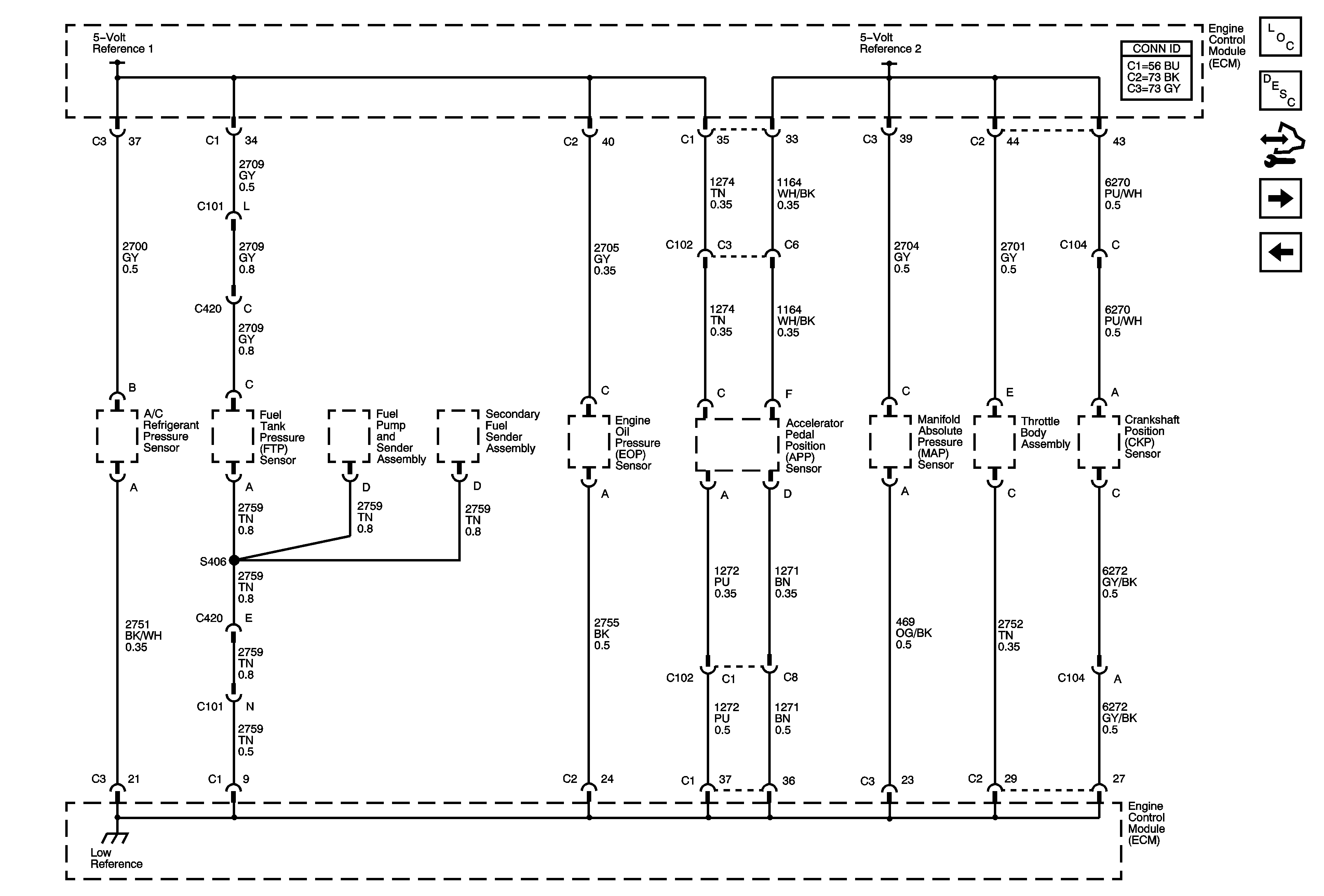
Figure 2:

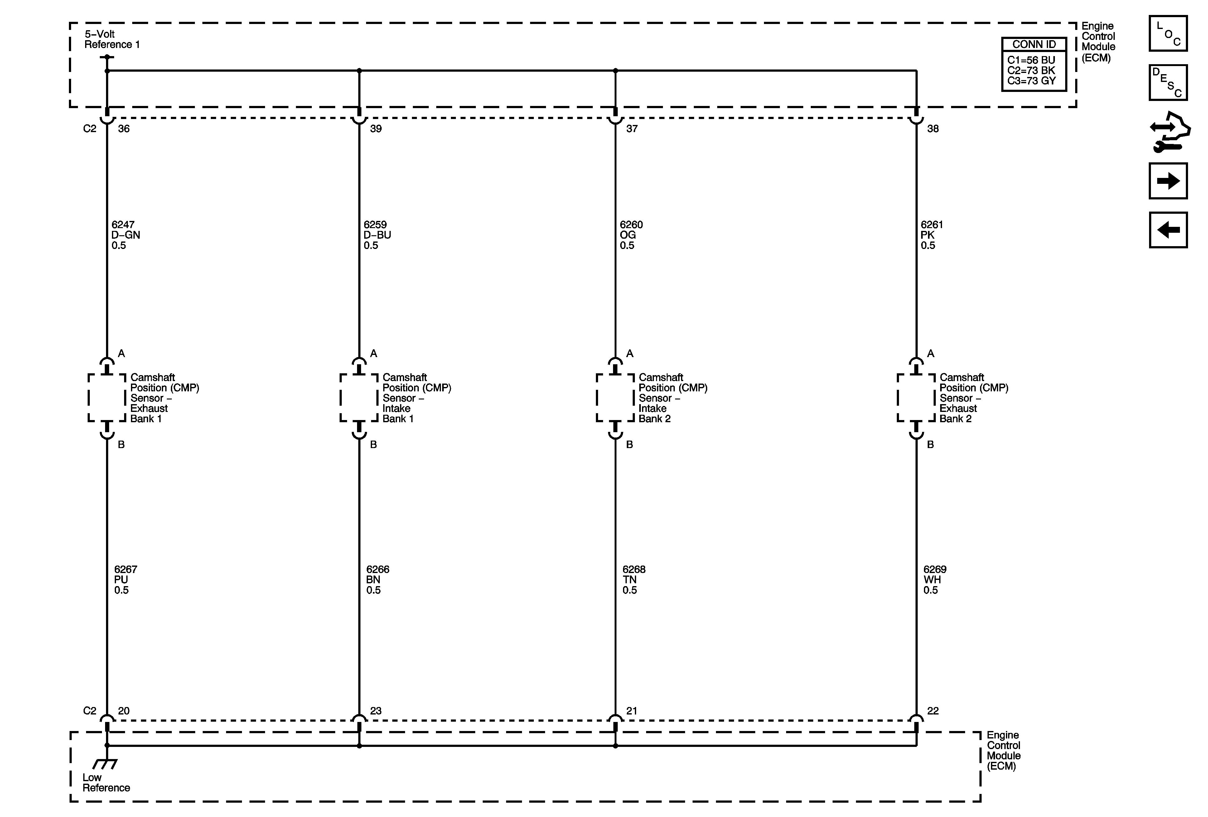
Engine Data Sensors - 5-Volt and Low Reference

Object Number: 1821913  Size: FS
Master Electrical Component List
Engine Control Module Description
Control Module References
Ignition Controls - CMP Sensors and Solenoids
ECM Power, Ground, Serial Data, and MIL
Figure 3:

Ignition Controls - CMP Sensors and Solenoids


Object Number: 1845306  Size: FS
Master Electrical Component List
Engine Control Module Description
Control Module References
Engine Data Sensors - Pressure, Temperature, MAF, VSS
Engine Data Sensors - 5-Volt and Low References 1 of 2
Figure 4:

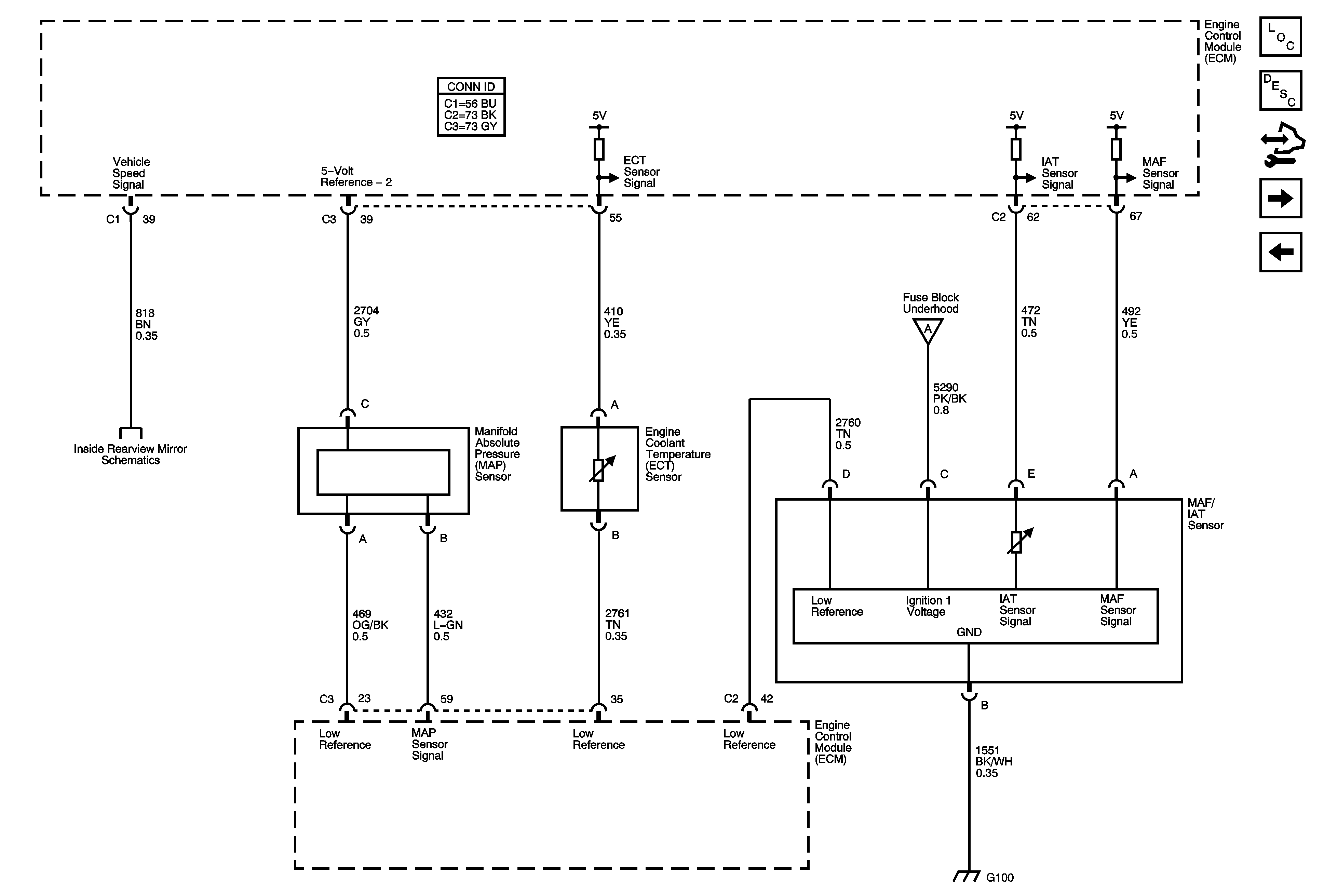
Engine Data Sensors - Pressure, Temperature, MAF, VSS


Object Number: 1821929  Size: FS
Master Electrical Component List
Engine Control Module Description
Control Module References
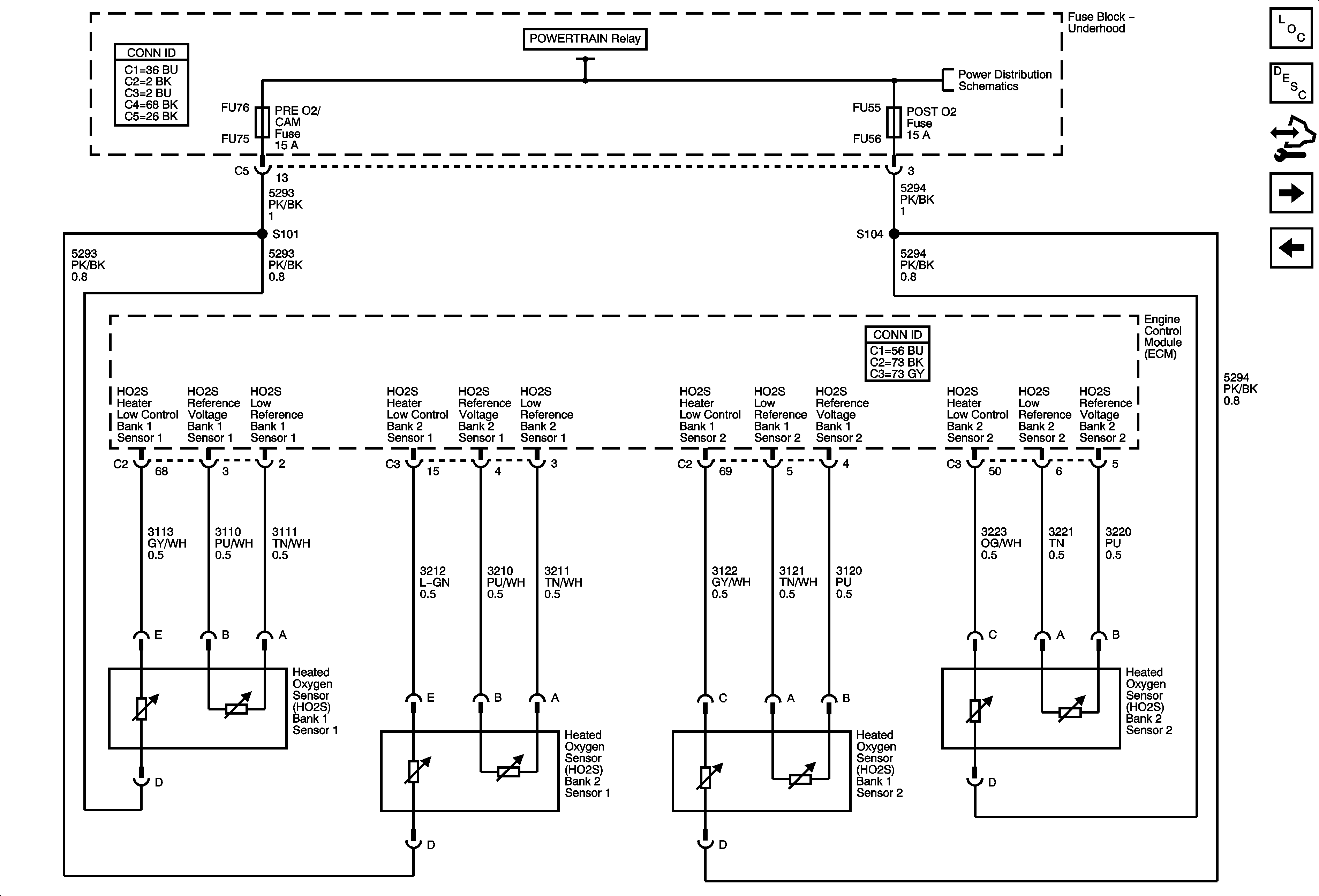
Engine Data Sensors - Oxygen Sensors
Ignition Controls - CMP Sensors and Solenoids
ECM Power, Ground, Serial Data, and MIL
Automatic Headlamp Dimming Signals
07 STS Ground Distribution - G100 (LH2/LC3)
Figure 5:

Engine Data Sensors - Oxygen Sensors


Object Number: 1820888  Size: FS
Master Electrical Component List
Engine Control Module Description
Control Module References
Engine Data Sensors - Electronic Throttle Controls
Engine Data Sensors - Pressure, Temperature, MAF, VSS
Fuse Block - Underhood: Main, Low Speed, Hi Speed, and S/P Fan Relays, V8 ECM, PRE O2/CAM, HFV6 ECM, Low Speed Fan, Hi Speed Fan Fuses
Figure 6:

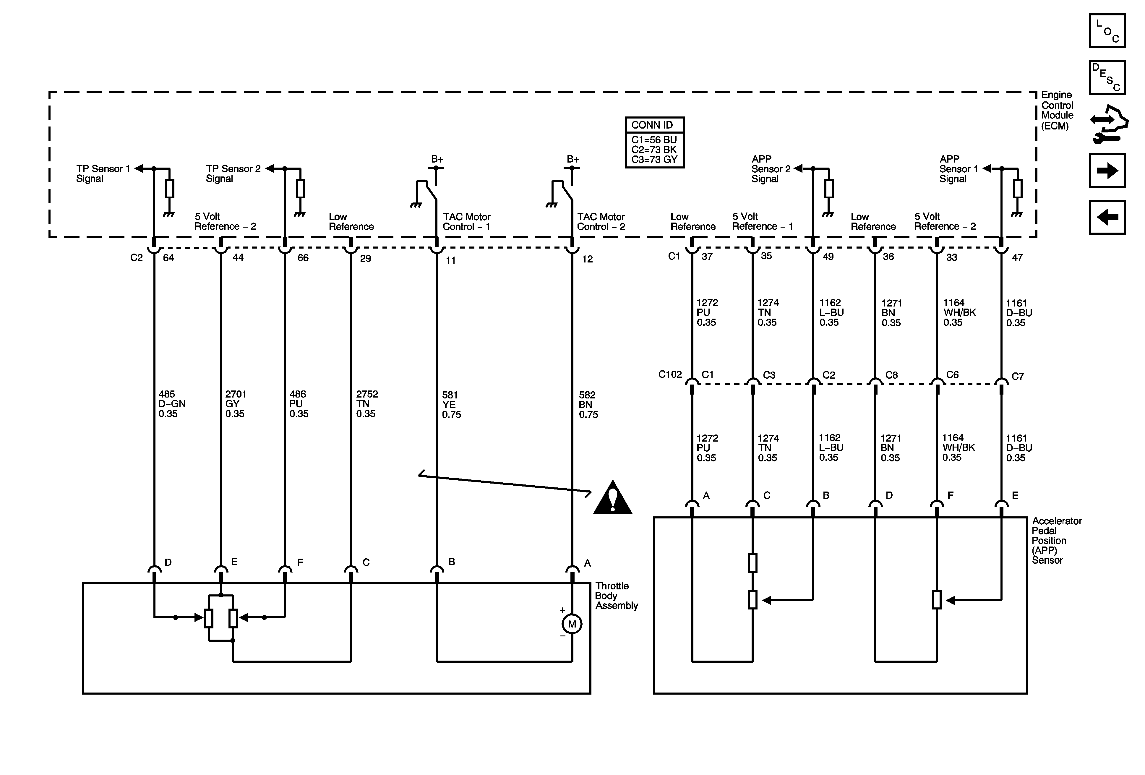
Engine Data Sensors - Electronic Throttle Controls


Object Number: 1821988  Size: FS
Master Electrical Component List
Engine Control Module Description
Control Module References
Ignition Controls - Ignition System Bank 1
Engine Data Sensors - Oxygen Sensors
Figure 7:

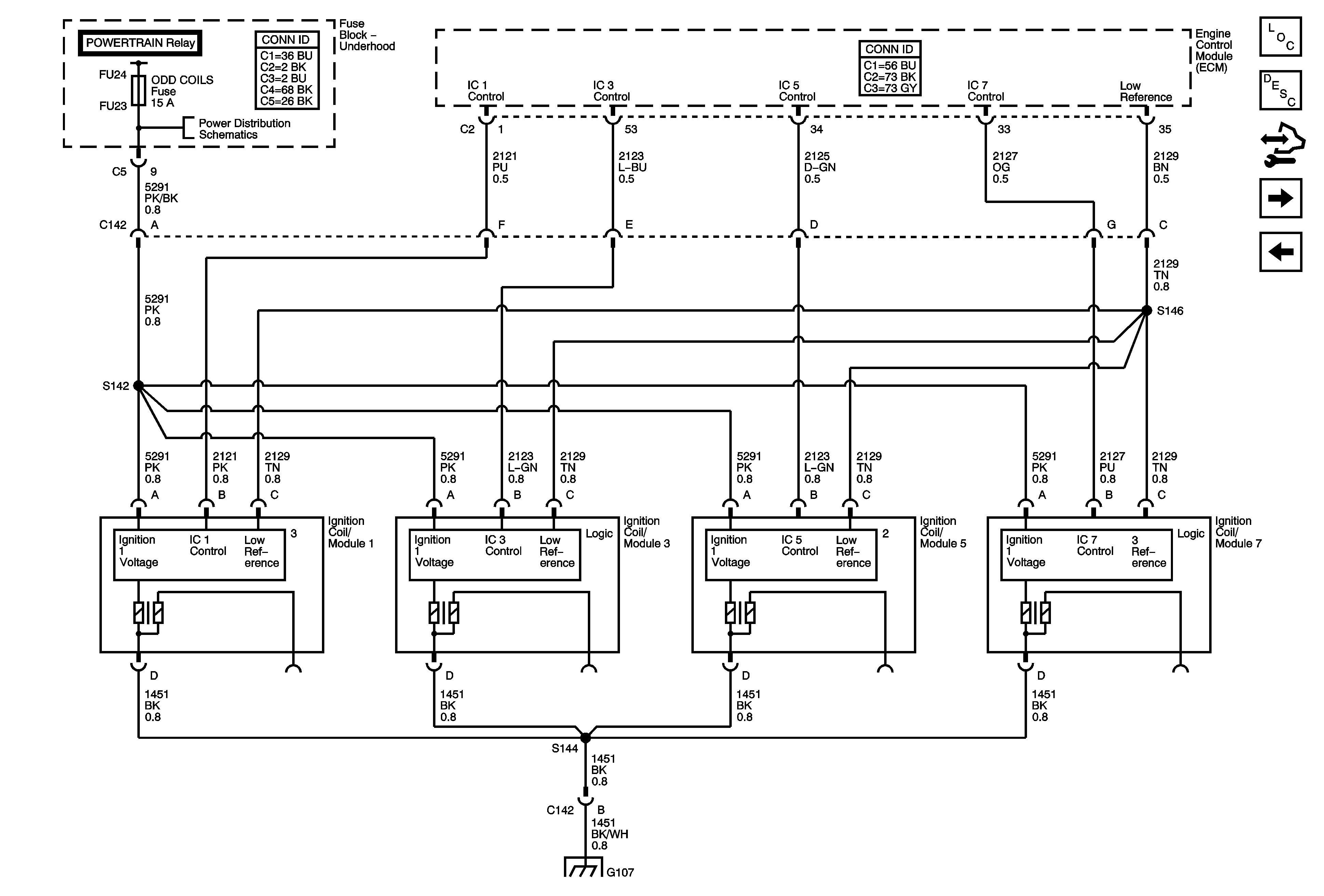
Ignition Controls - Ignition System Bank 1


Object Number: 1821933  Size: FS
Master Electrical Component List
Engine Control Module Description
Control Module References
Ignition Controls - Ignition System Bank 2
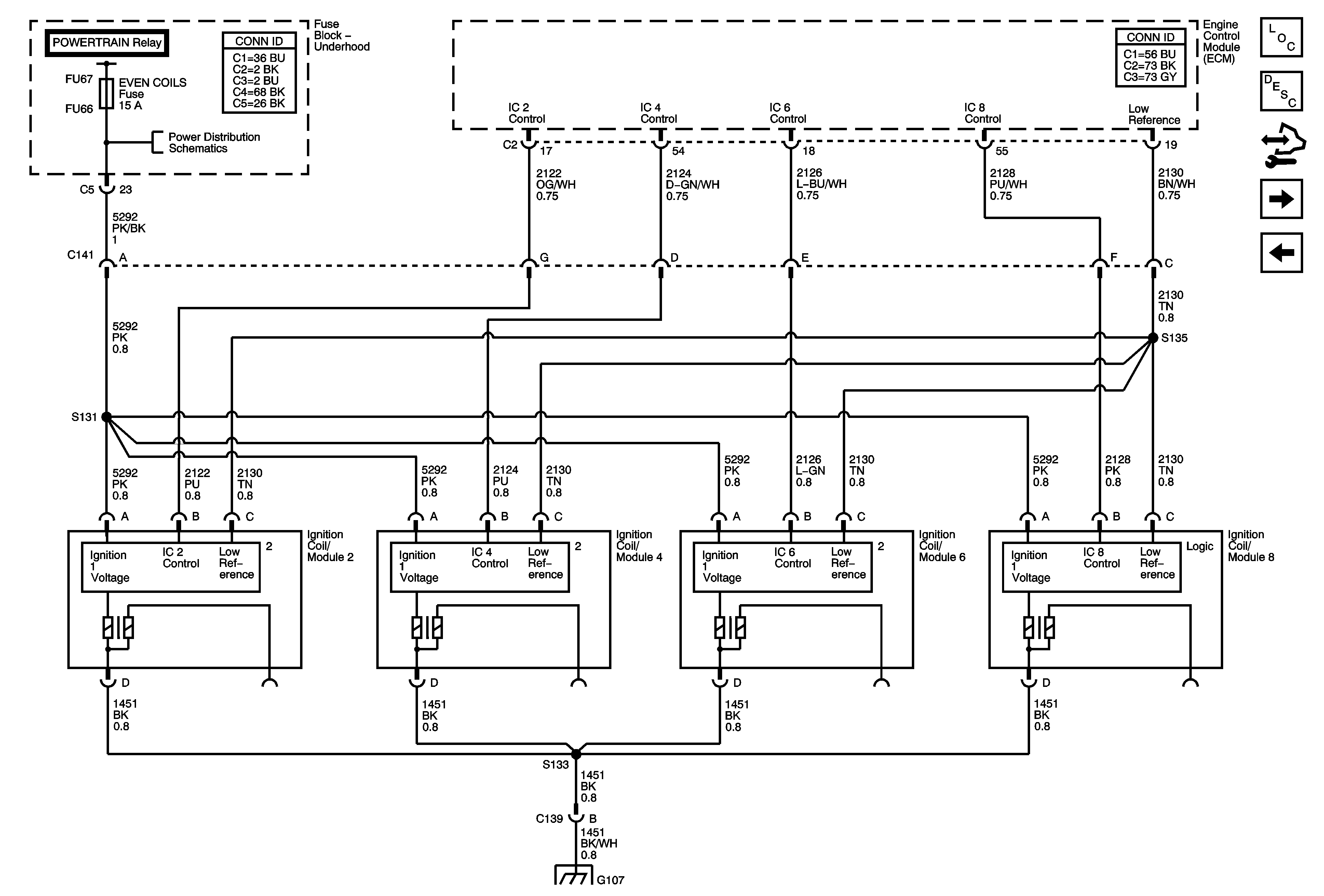
Engine Data Sensors - Electronic Throttle Controls
Fuse Block - Underhood: Odd Inj/Coils, Even Inj/Coils and Post O2 Fuses
G107 (LH2/LC3), G113 (LY7)
Figure 8:

Ignition Controls - Ignition System Bank 2


Object Number: 1821998  Size: FS
Master Electrical Component List
Engine Control Module Description
Control Module References
Ignition Controls - CMP Sensors and Solenoids
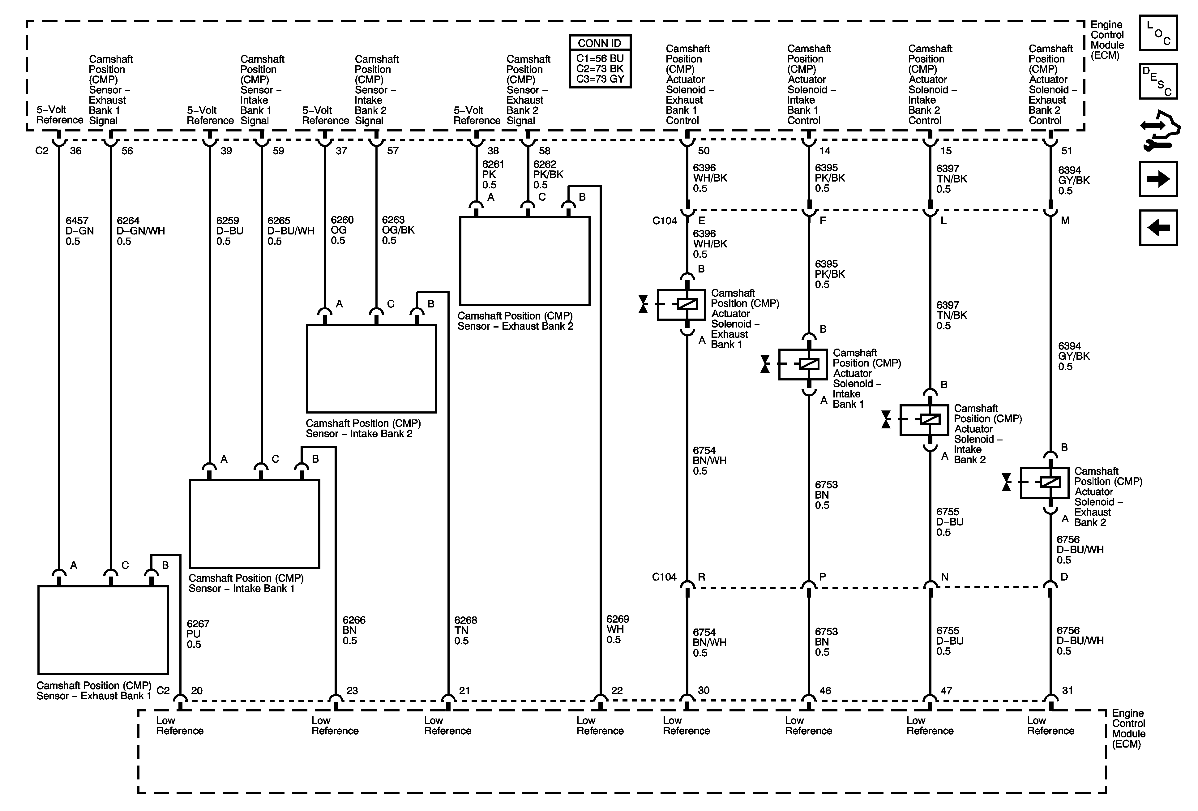
Ignition Controls - Ignition System Bank 1
Fuse Block - Underhood: Odd Inj/Coils, Even Inj/Coils and Post O2 Fuses
G107 (LH2/LC3), G113 (LY7)
Figure 9:

Ignition Controls - CMP Sensors and Solenoids


Object Number: 1822002  Size: FS
Master Electrical Component List
Engine Control Module Description
Control Module References
Crankshaft Position (CKP) Sensor and Knock Sensors
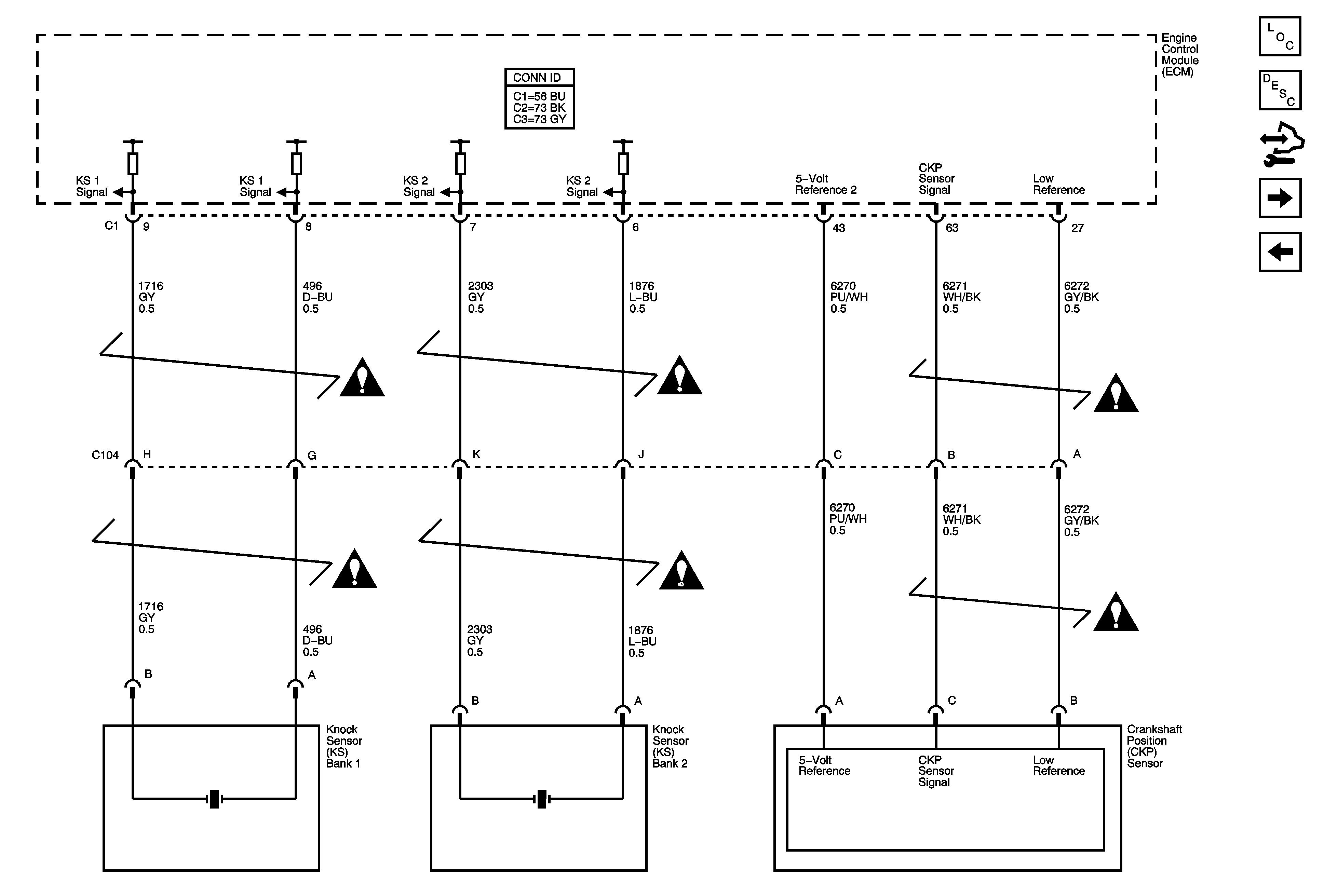
Ignition Controls - Ignition System Bank 2
Figure 10:

Crankshaft Position (CKP) Sensor and Knock Sensors


Object Number: 1822009  Size: FS
Master Electrical Component List
Engine Control Module Description
Control Module References
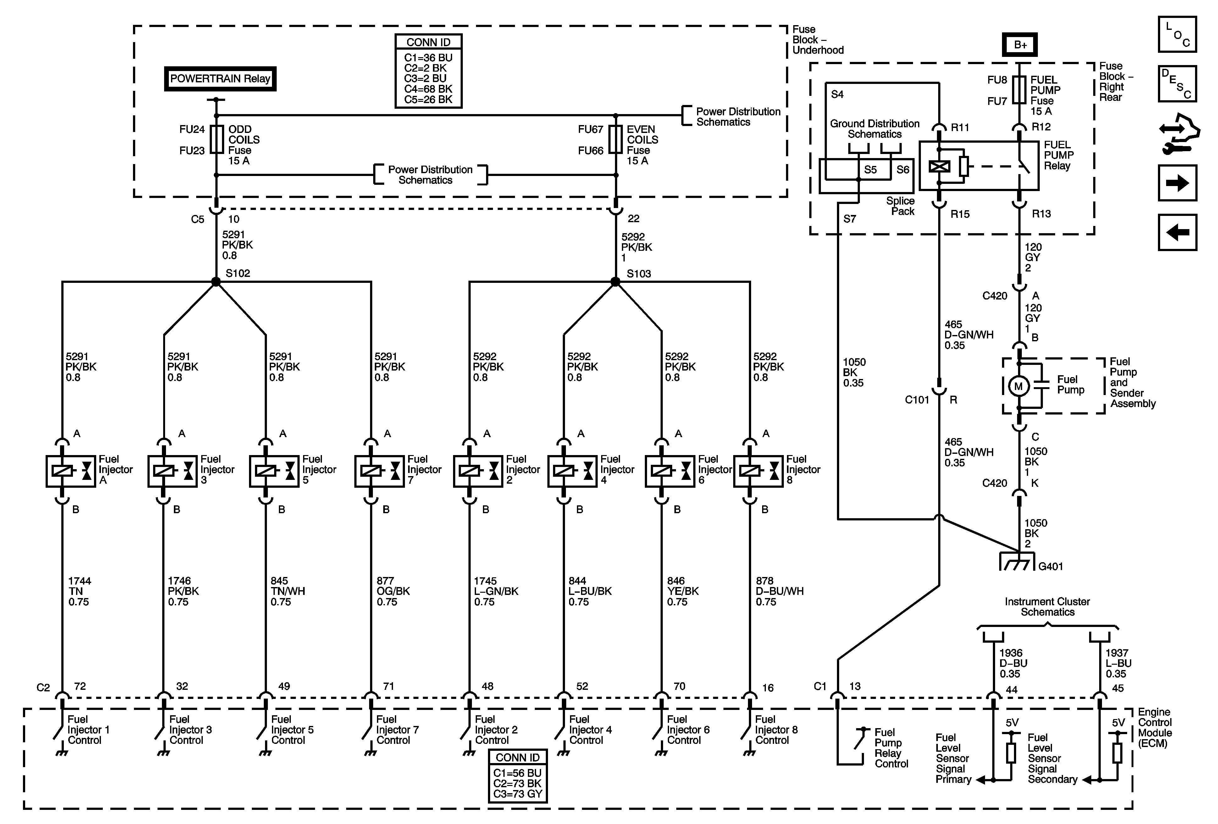
Fuel Controls - Injector and Pump
Ignition Controls - CMP Sensors and Solenoids
Engine Controls Schematic Icons
Figure 11:

Fuel Controls - Injectors and Pump


Object Number: 1822013  Size: FS
Master Electrical Component List
Engine Control Module Description
Control Module References
Fuel Controls - EVAP and Fuel Tank Pressure (FTP) Sensor
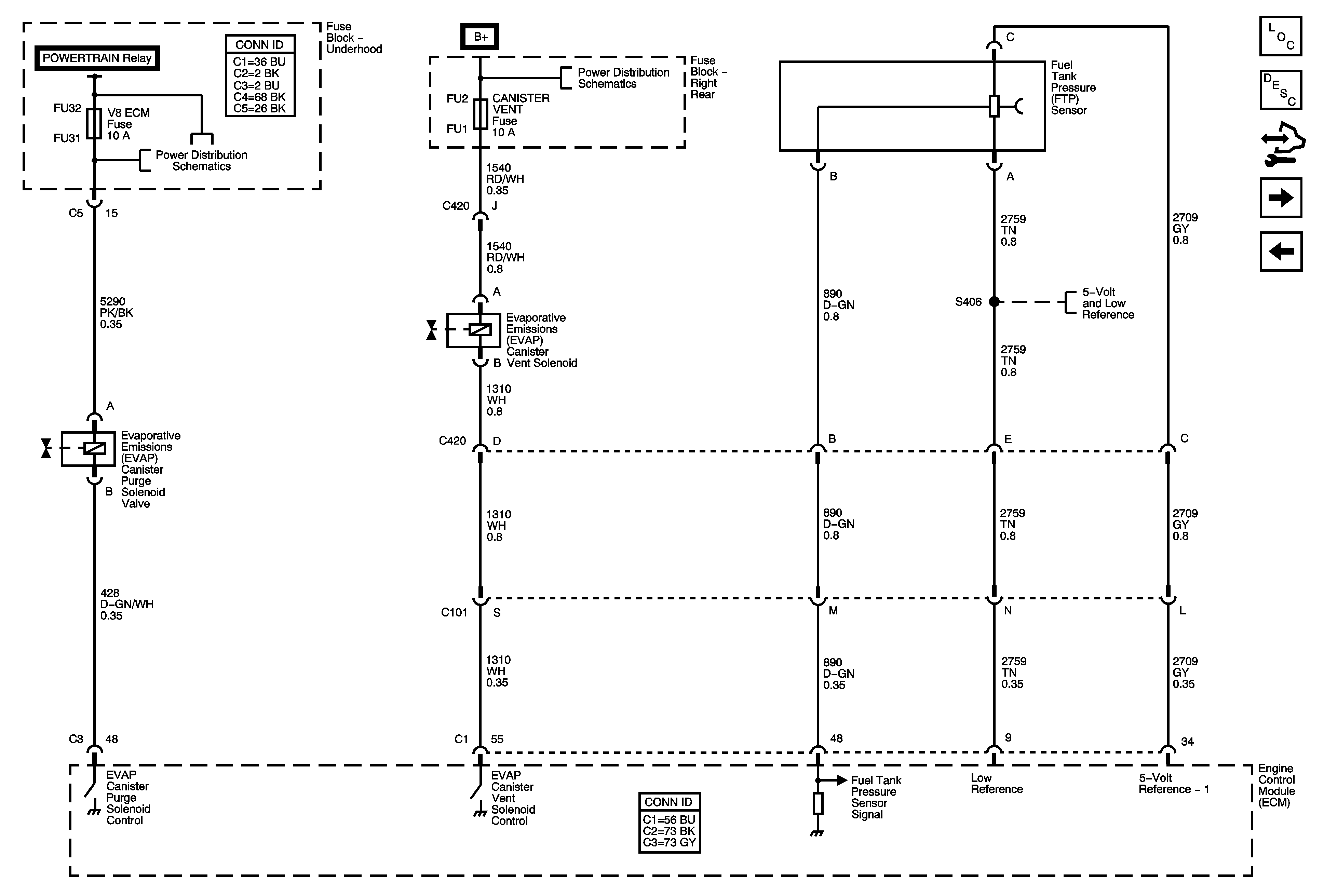
Crankshaft Position (CKP) Sensor and Knock Sensors
Fuse Block - Underhood: Odd Inj/Coils, Even Inj/Coils and Post O2 Fuses
G401 (1 of 2)
G401 (1 of 2)
Engine Oil and Fuel Tank Level
Figure 12:

Fuel Controls - EVAP and Fuel Tank Pressure (FTP) Sensor


Object Number: 1822050  Size: FS
Master Electrical Component List
Engine Control Module Description
Control Module References
Fuel Controls - Controlled/Monitored Subsystem References
Fuel Controls - Injector and Pump
Fuse Block - Underhood: Main, Low Speed, Hi Speed, and S/P Fan Relays, V8 ECM, PRE O2/CAM, HFV6 ECM, Low Speed Fan, Hi Speed Fan Fuses
Fuse Block - Left Rear Bussing
Engine Data Sensors - 5-Volt and Low References 1 of 2
Figure 13:

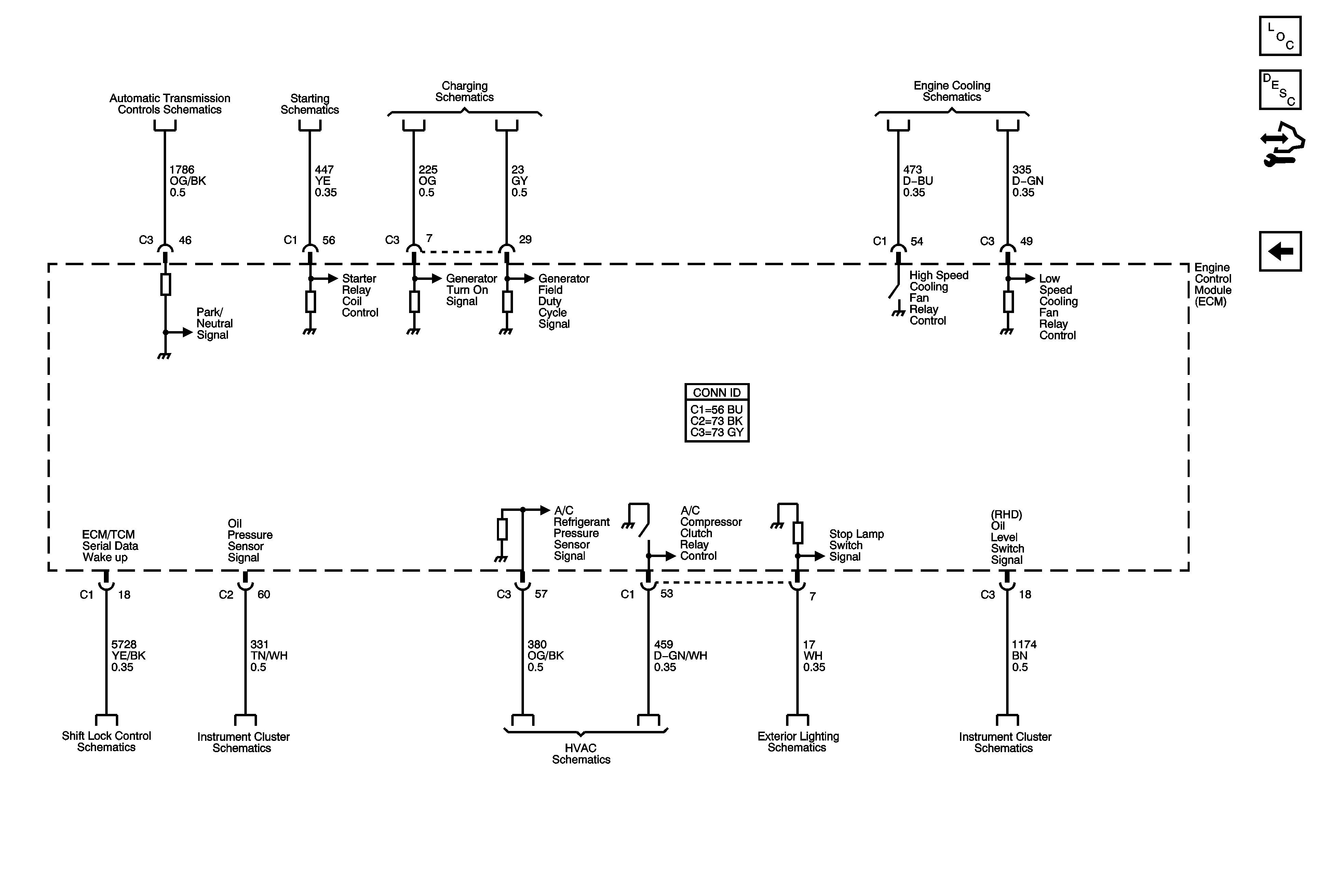
Controlled/Monitored Subsystem References


Object Number: 1822055  Size: FS
Master Electrical Component List
Engine Control Module Description
Control Module References
Fuel Controls - EVAP and Fuel Tank Pressure (FTP) Sensor
TCM Power, Grounds, and DLC (LY7/LH2)
Starting System - LH2
Charging System
Cooling Fans
Automatic Transmission Shift Lock Control Schematics
Indicators
A/C Refrigerant Pressure Sensor and Compressor Clutch
Backup Lamps, CHMSL - Domestic and Export
Engine Oil and Fuel Tank Level