Tools Required
| • | EN-47814 Supercharger Bypass Valve Actuator Setting Tool |
| • | EN-47833 Supercharger Service Holding Fixture |
Disassemble Procedure
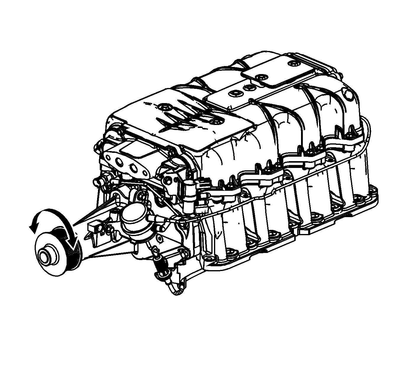
- Ensure the supercharger will spin.
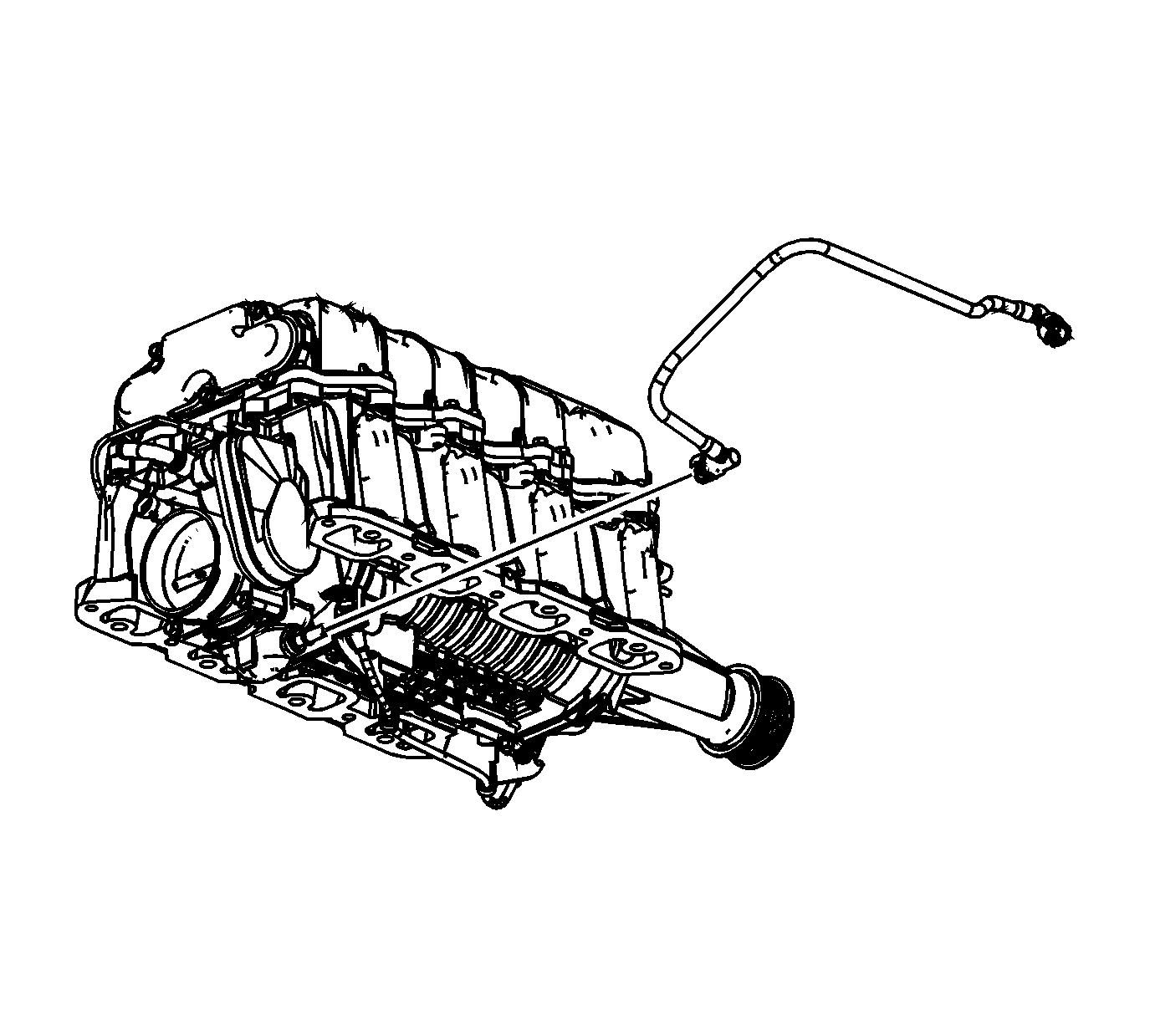
- Disconnect and remove the dirty air positive crankcase ventilation (PCV) tube from the supercharger.
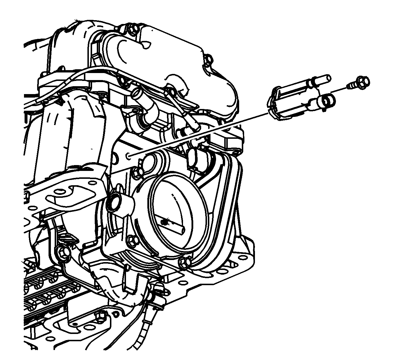
- Remove the evaporative emission (EVAP) canister purge solenoid valve bolt.
- Remove the EVAP canister purge solenoid valve.
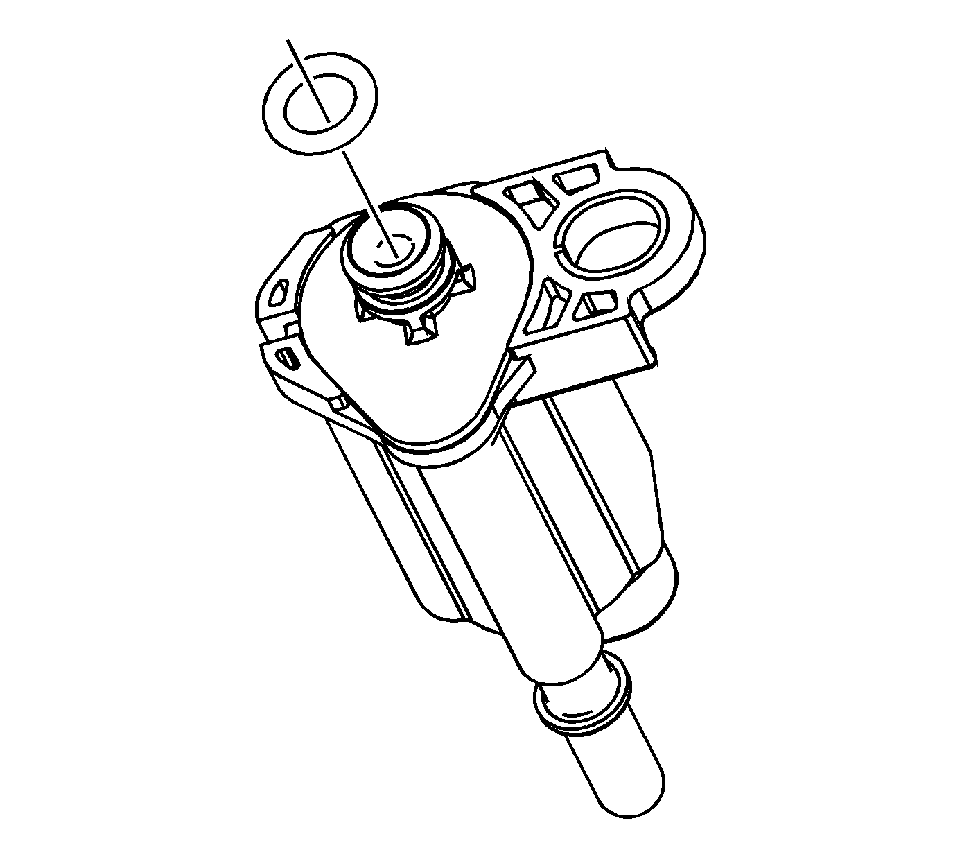
- Remove and discard the O-ring from the EVAP canister purge solenoid valve.
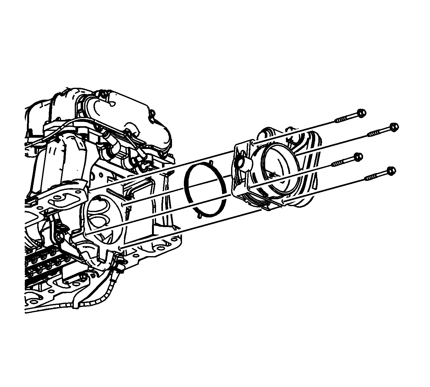
- Remove the throttle body bolts.
- Remove the throttle body.
- Remove and discard the throttle body O-ring.
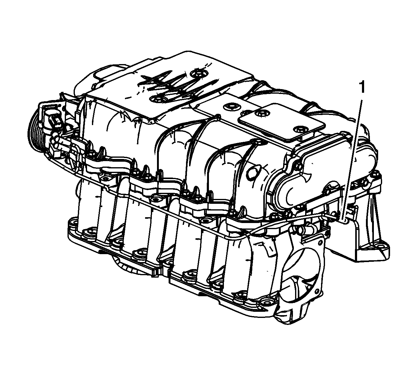
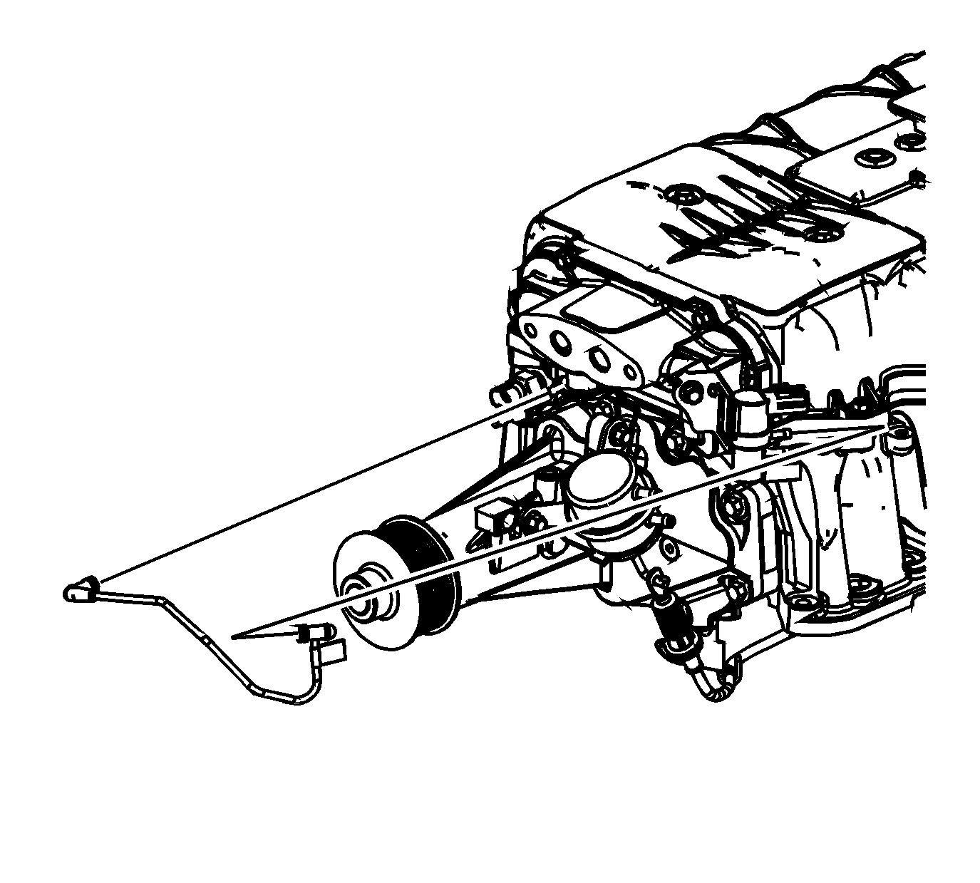
- Disconnect the bypass valve actuator vacuum hose at the vacuum port of the supercharger (1).
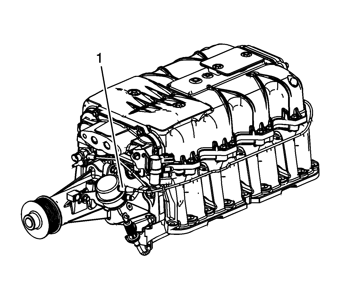
- Disconnect the bypass valve actuator vacuum hose at the supercharger bypass valve actuator (1).
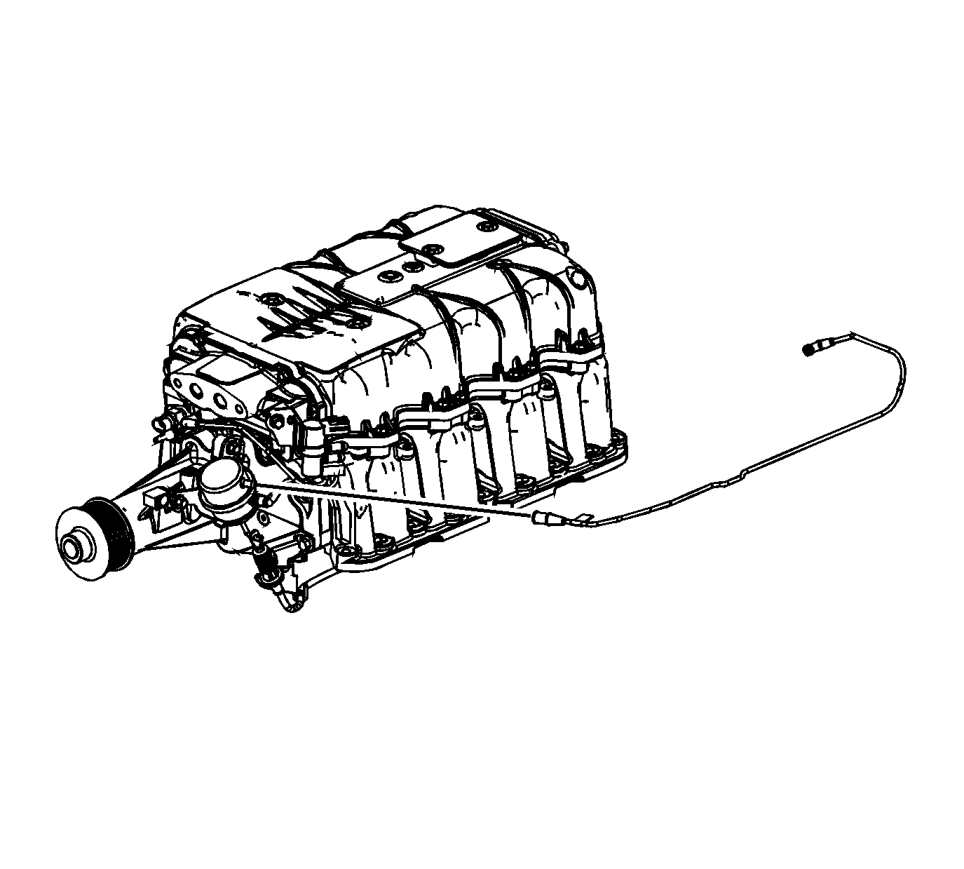
- Remove the bypass valve actuator vacuum hose from the supercharger.
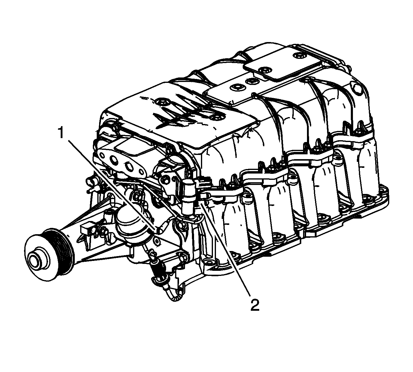
- Disconnect the bypass valve actuator pressure hose at the supercharger bypass valve actuator (1).
- Disconnect the bypass valve actuator pressure hose at the charge air bypass regulator solenoid valve (2).
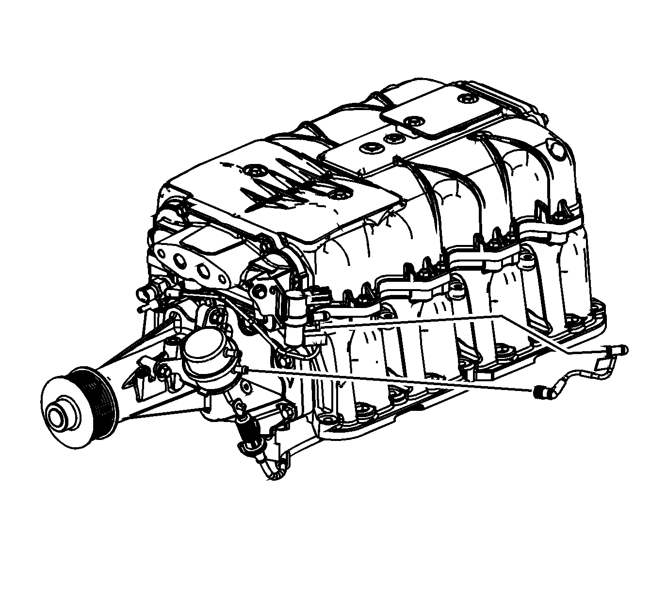
- Remove the bypass valve actuator pressure hose.
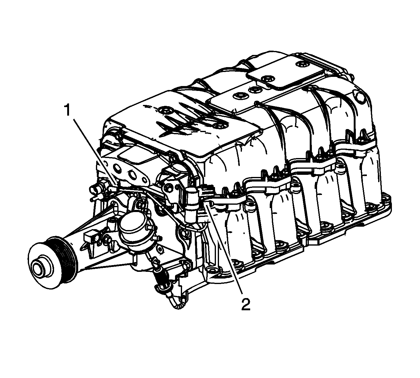
- Disconnect the charge air bypass regulator solenoid valve pressure hose at the supercharger pressure port (1).
- Disconnect the charge air bypass regulator solenoid valve pressure hose at the charge air bypass regulator solenoid valve (2).
- Remove the charge air bypass regulator solenoid valve pressure hose.
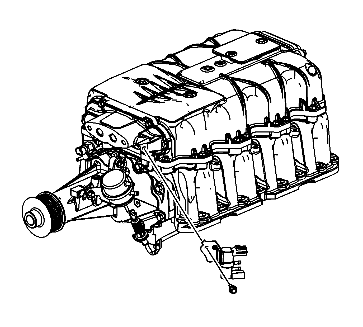
- Remove the charge air bypass regulator solenoid valve bolt.
- Remove the charge air bypass regulator solenoid valve.
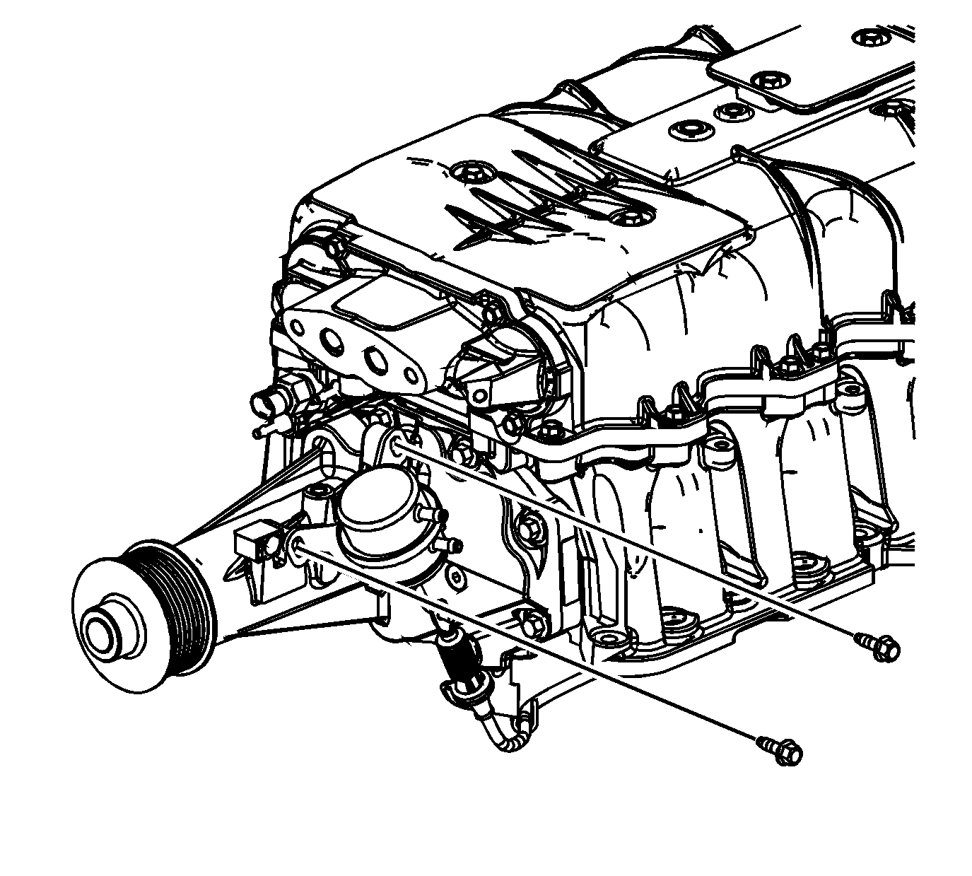
- Remove the bypass valve actuator bolts.
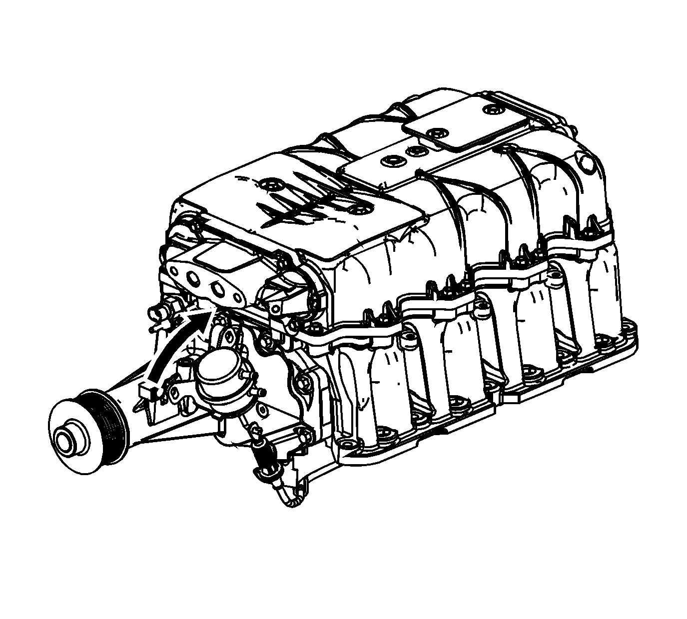
- Pivot the bypass valve actuator clockwise in order to remove the bypass valve actuator from the bypass valve actuator cable.
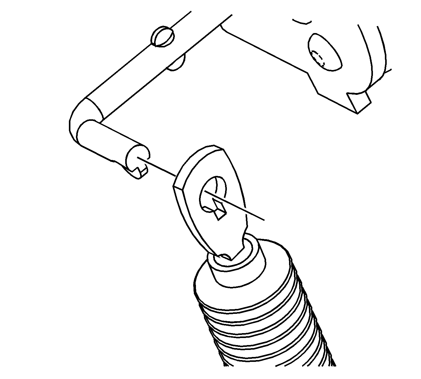
- Align the tab on the bypass valve actuator rod with the slot in the bypass valve actuator cable end.
- Slide the bypass valve actuator rod out of the bypass valve actuator cable.
- Remove the bypass valve actuator.
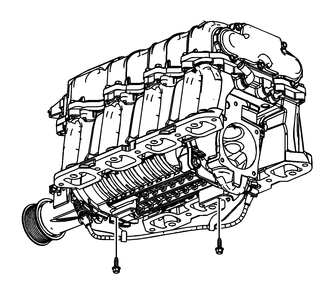
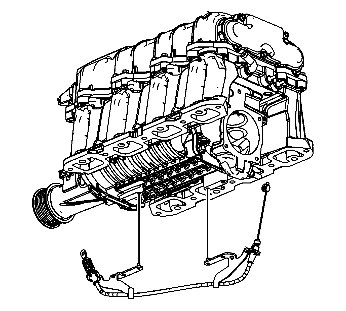
- Remove the bypass valve actuator cable bracket bolts from the supercharger.
- Slide the bypass valve actuator cable clip off of the pin on the supercharger bypass valve.
- Remove the bypass valve actuator cable.
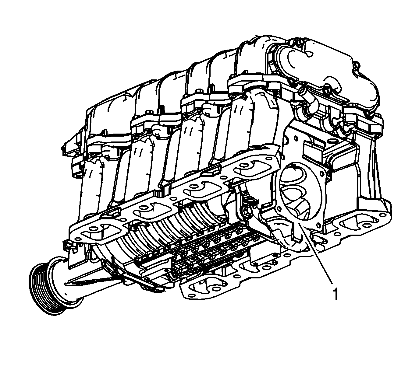
- Do NOT remove the supercharger bypass valve (1) from the supercharger.
- Remove the fuel injection fuel rail crossover tube clip.
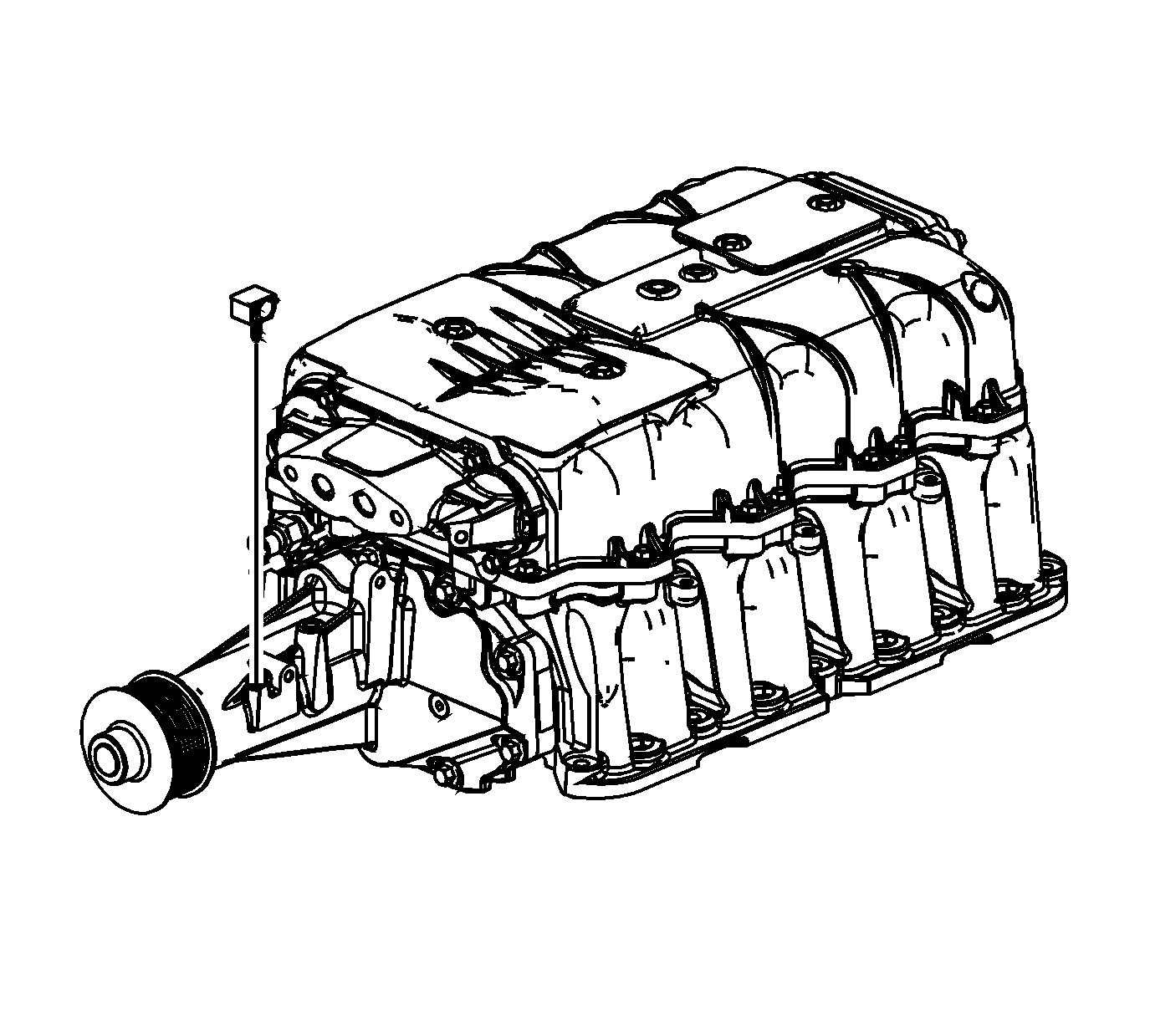
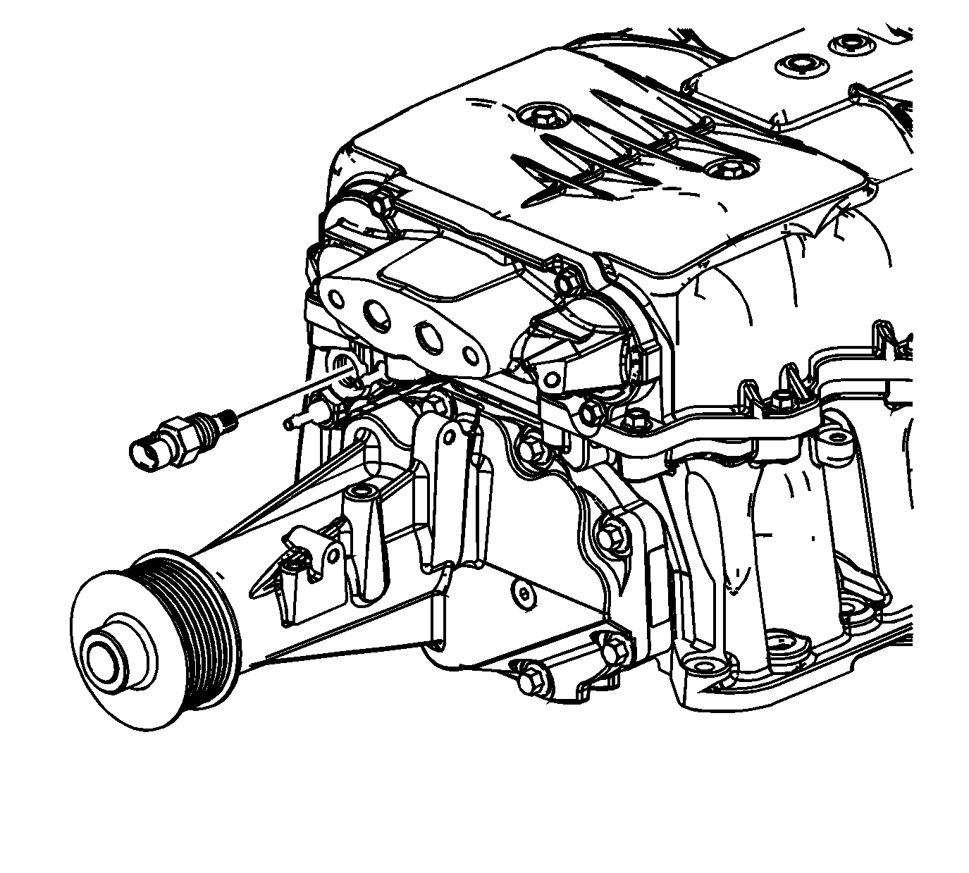
- Remove the intake air temperature (IAT) sensor 2 from the supercharger.
- Do NOT remove the following supercharger components:
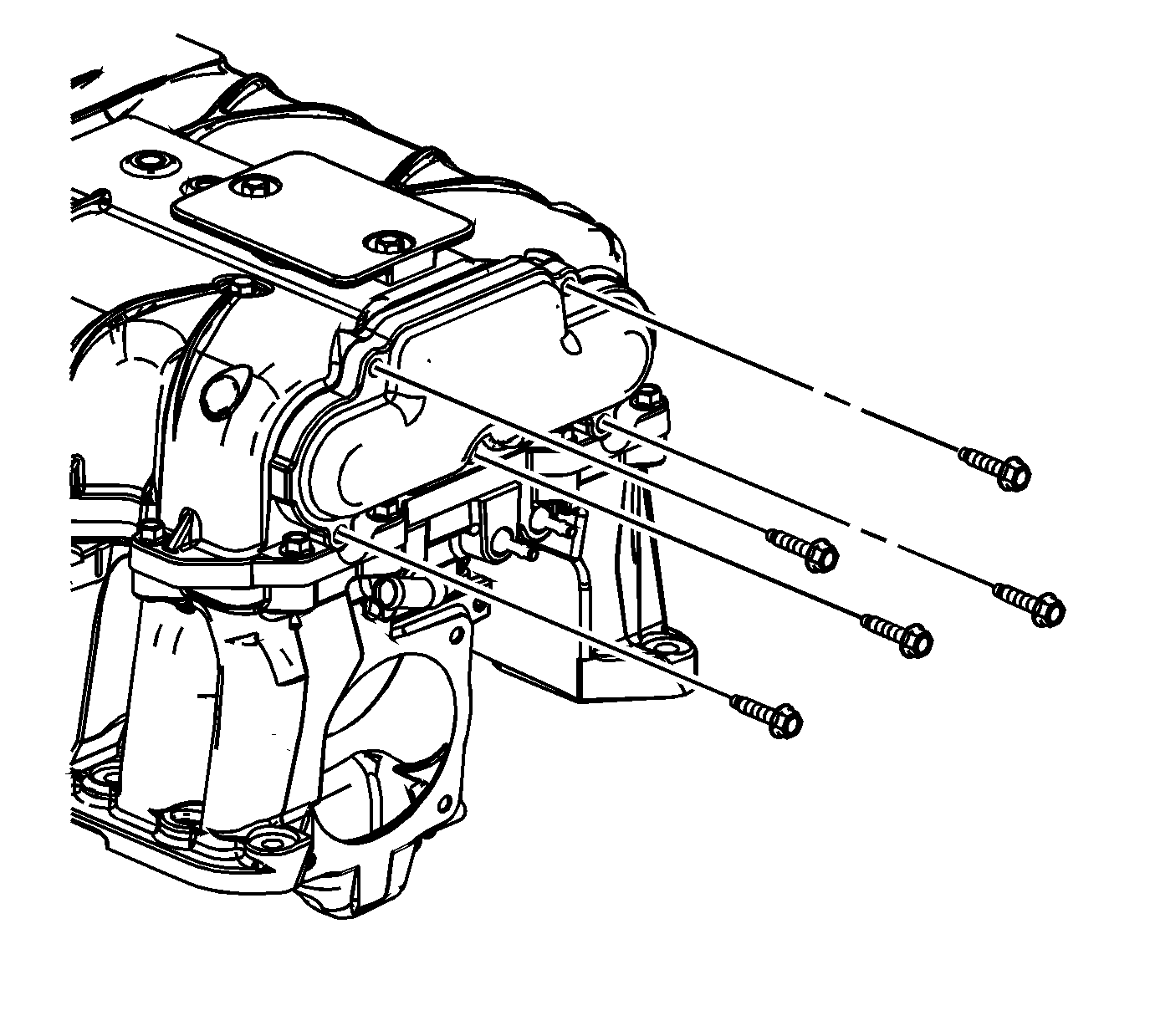
- Remove the charge air cooler front manifold bolts.
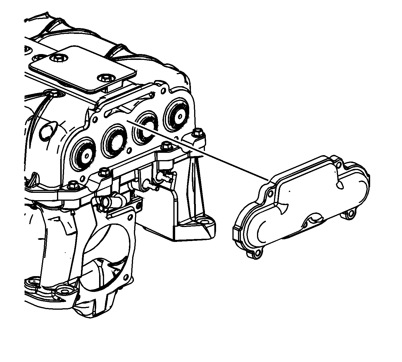
- Remove the charge air cooler front manifold.
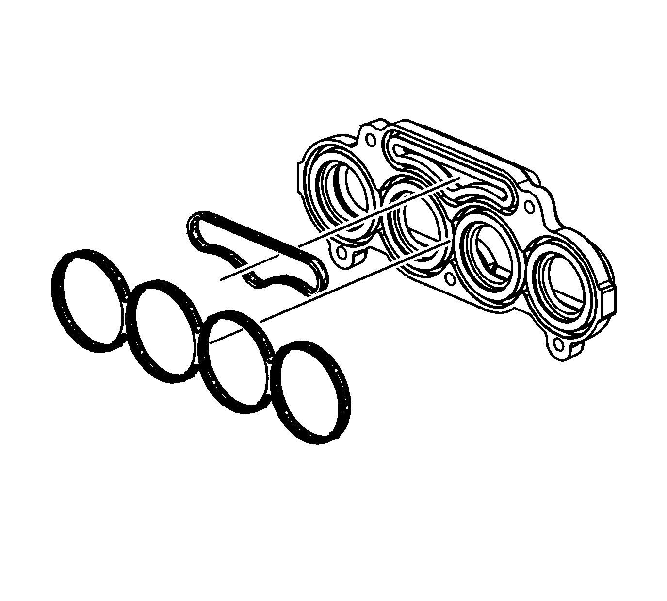
- Remove and discard the charge air cooler front manifold gasket.
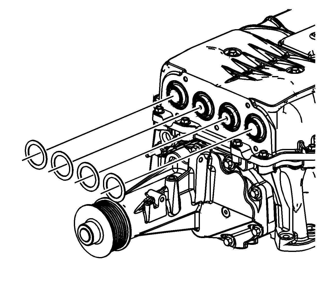
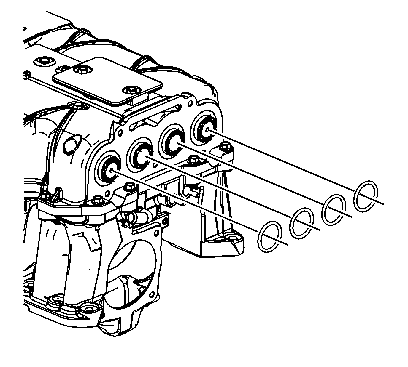
- Remove and discard the charge air cooler cooling tube front O-rings.
- Remove the charge air cooler cooling tube front spacers.
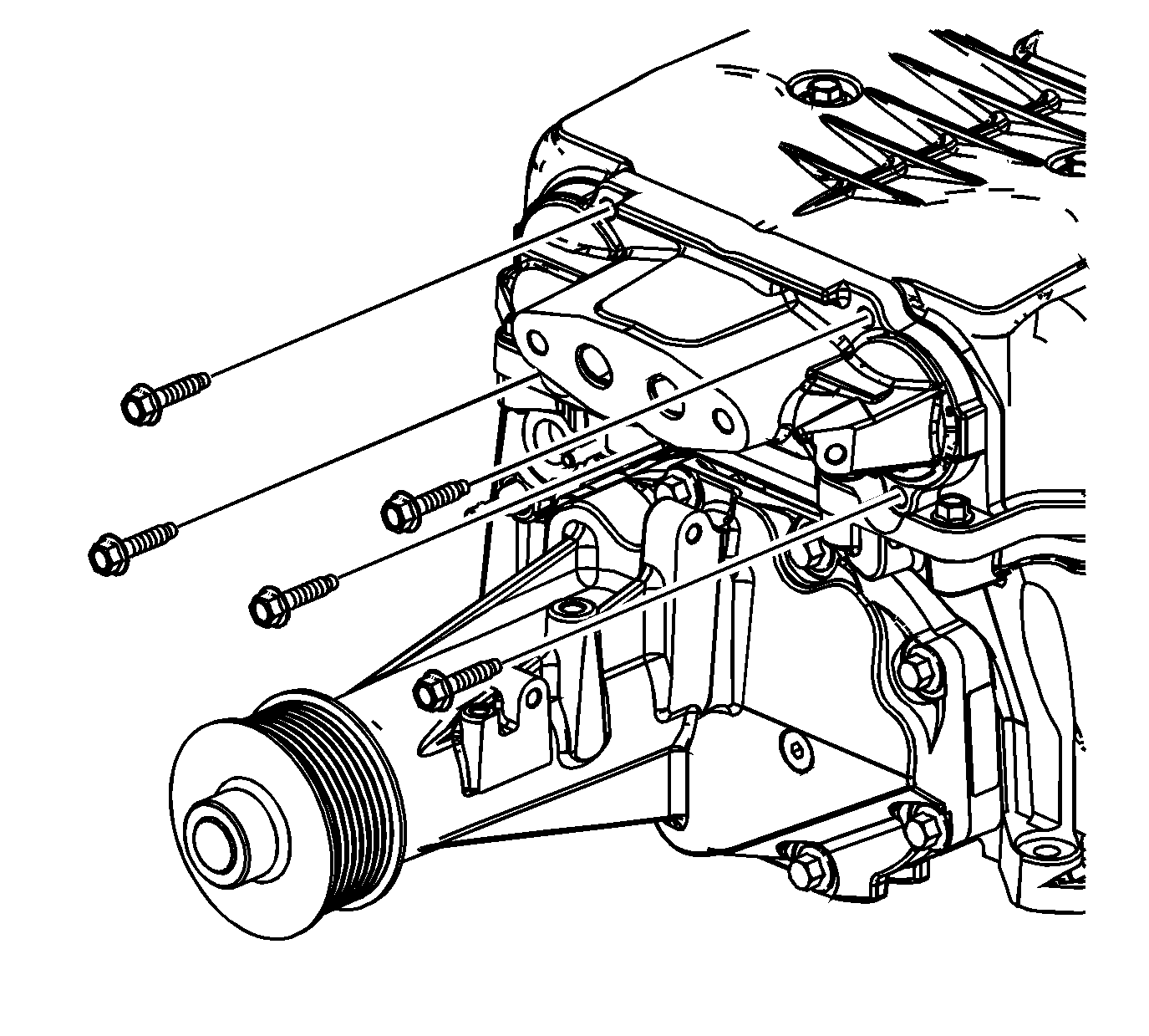
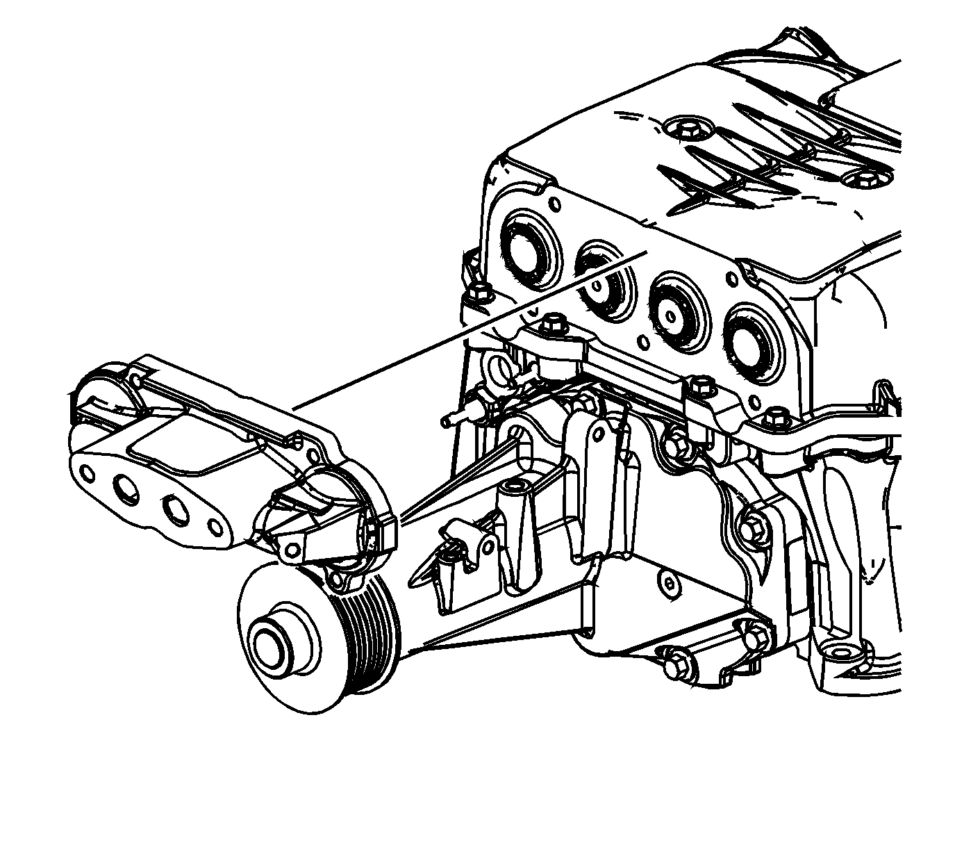
- Remove the charge air cooler rear manifold bolts.
- Remove the charge air cooler rear manifold.
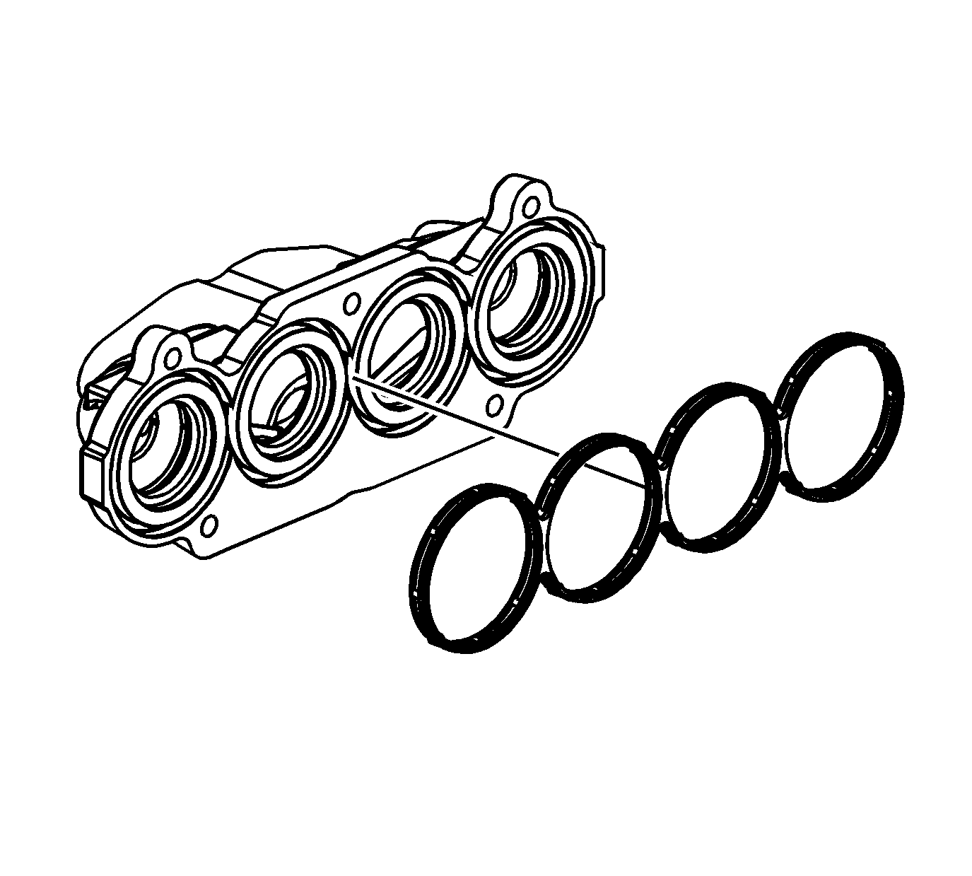
- Remove and discard the charge air cooler rear manifold gaskets.
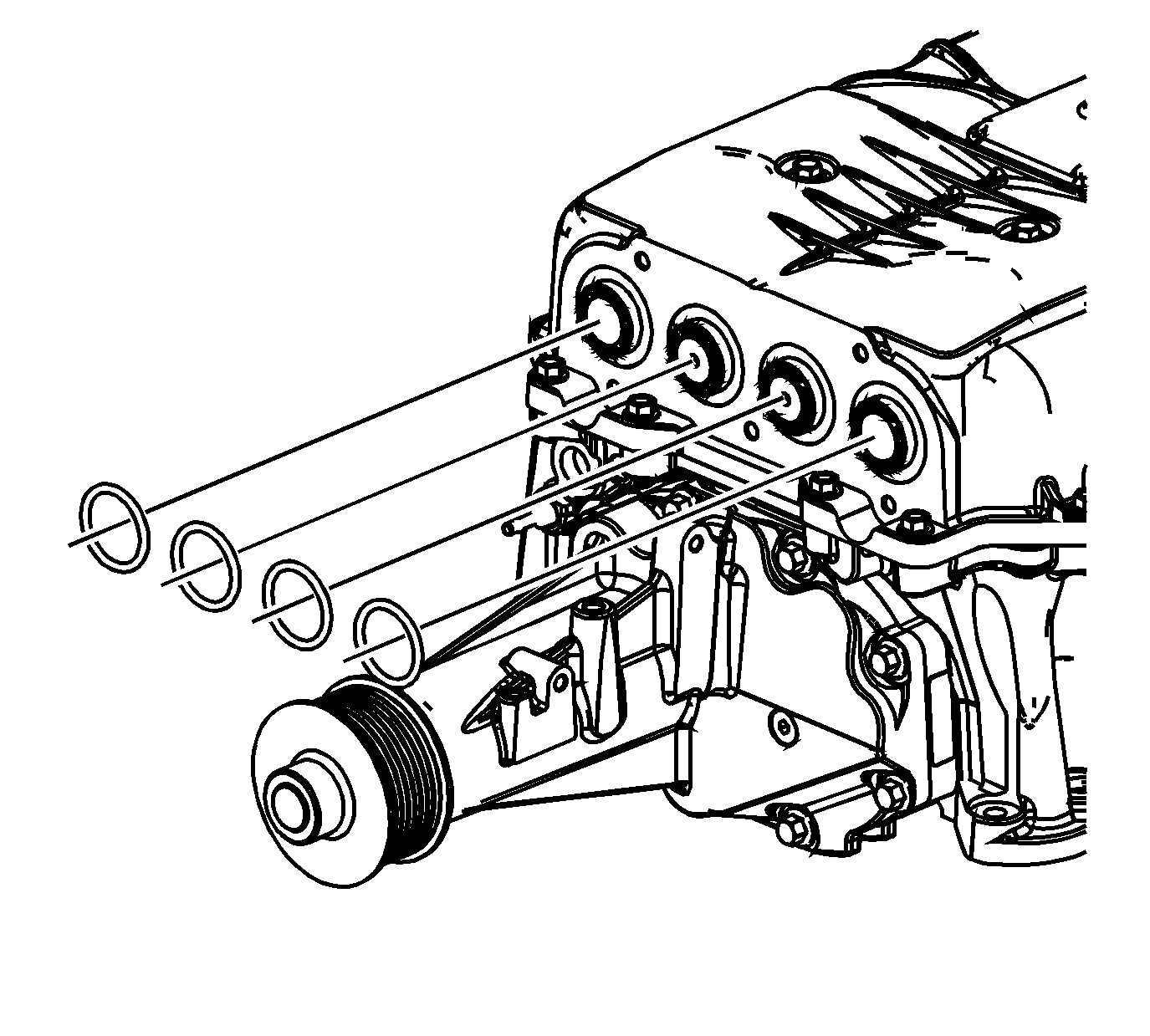
- Remove and discard the charge air cooler cooling tube rear O-rings.
- Remove the charge air cooler cooling tube rear spacers.
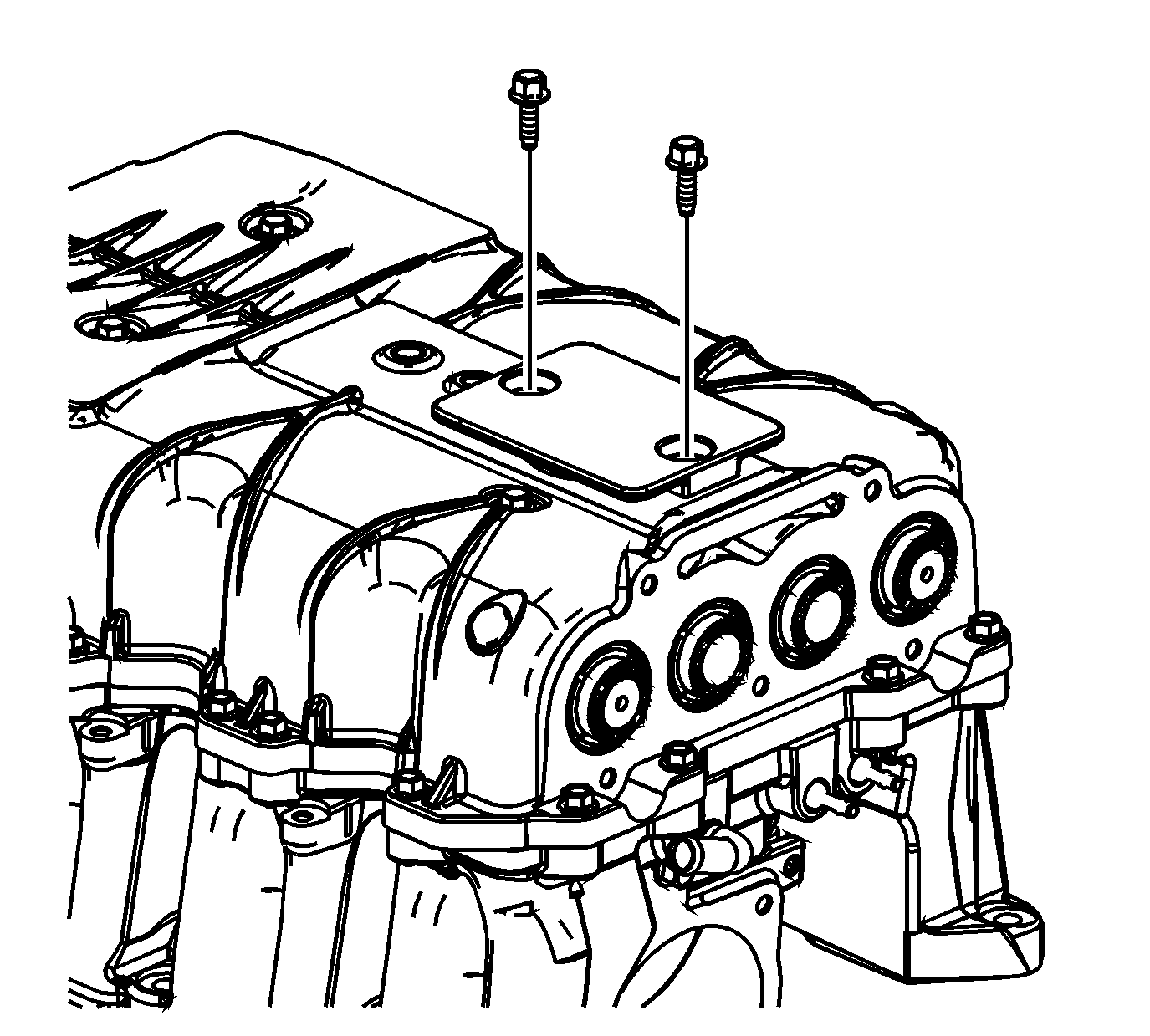
- Remove the charge air cooler cooling fill cap bolts.
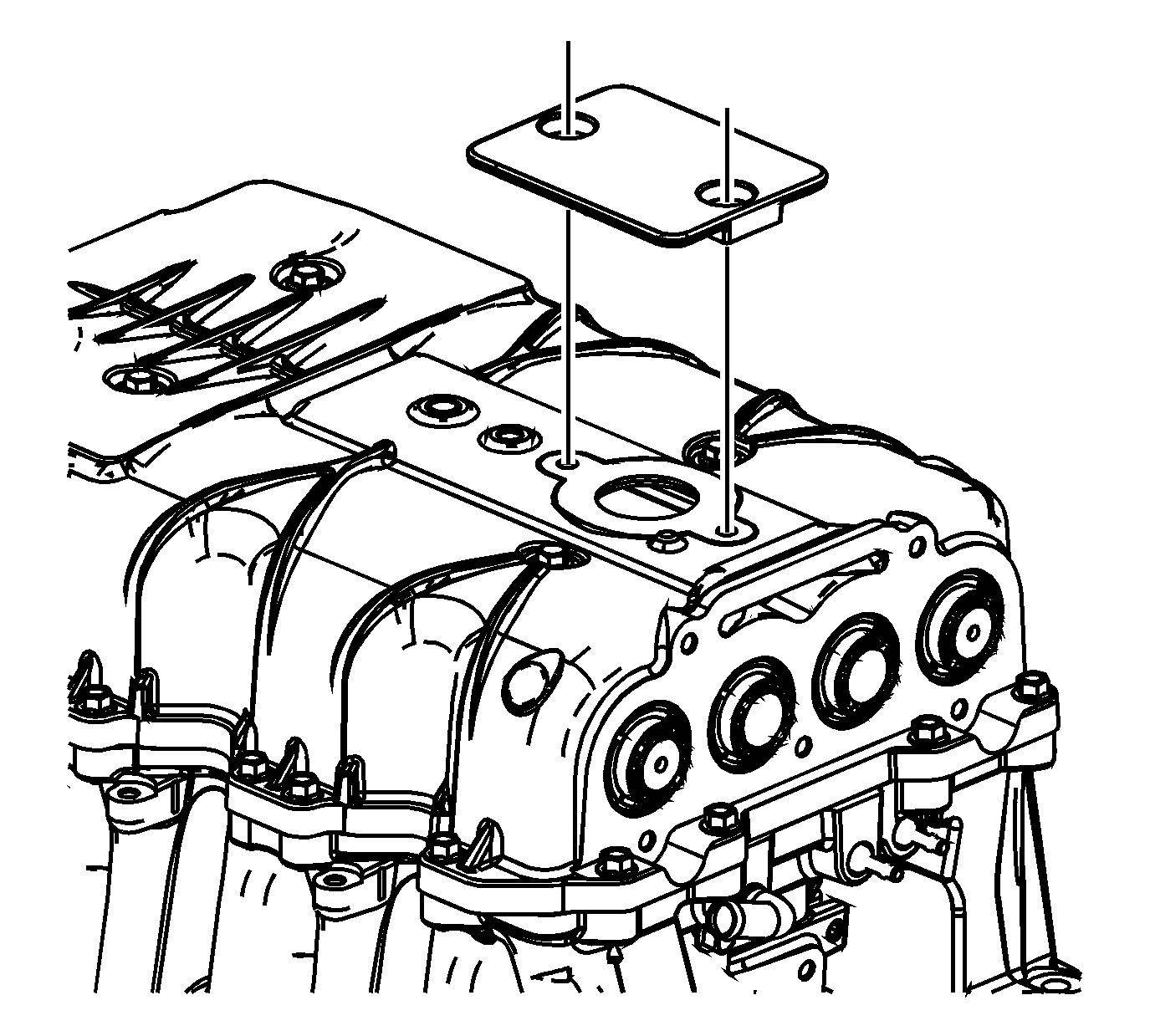
- Remove the charge air cooler cooling fill cap.
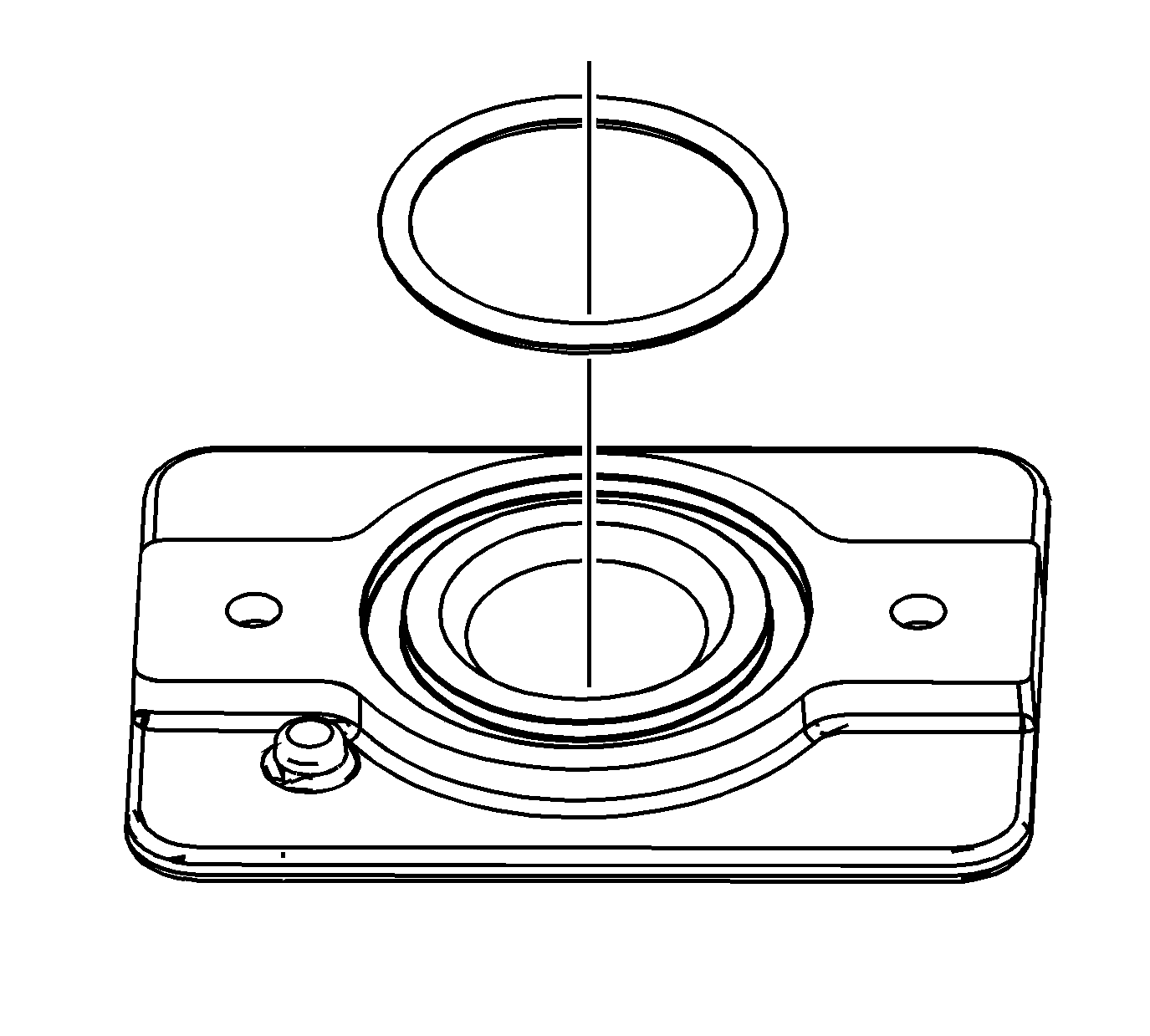
- Remove and discard the charge air cooler cooling fill cap O-ring.
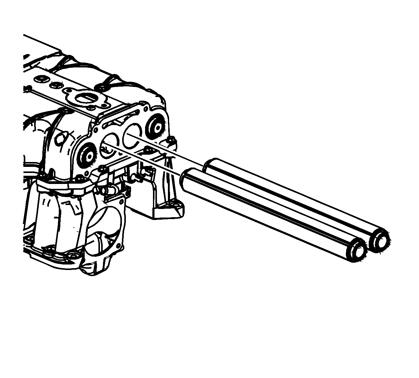
- Carefully remove the inboard charge air cooler cooling tubes.
- The charge air cooler cooling tubes are fragile and must be placed in a protected area.
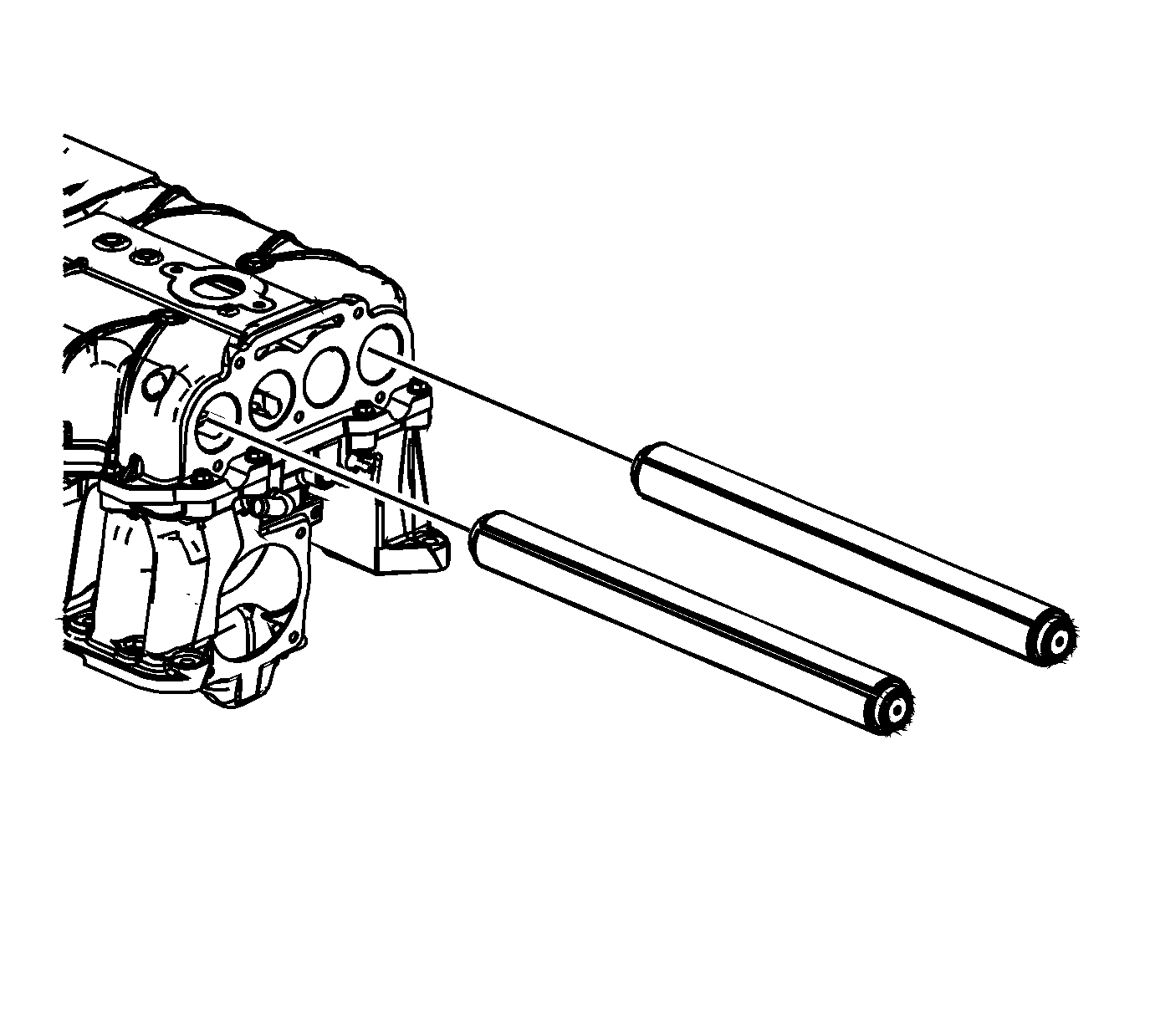
- Carefully remove the outboard charge air cooler cooling tubes.
- The charge air cooler cooling tubes are fragile and must be placed in a protected area.
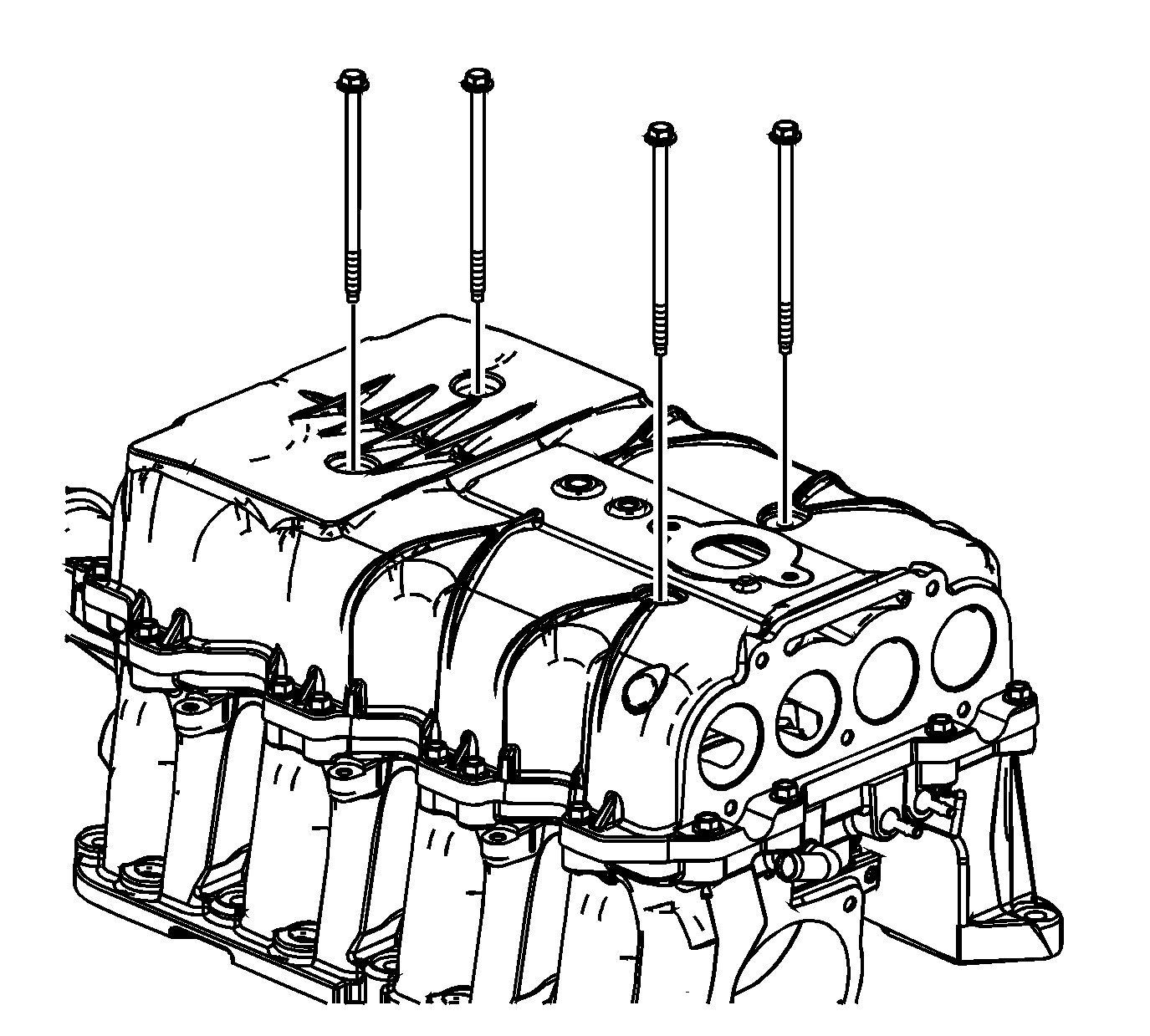
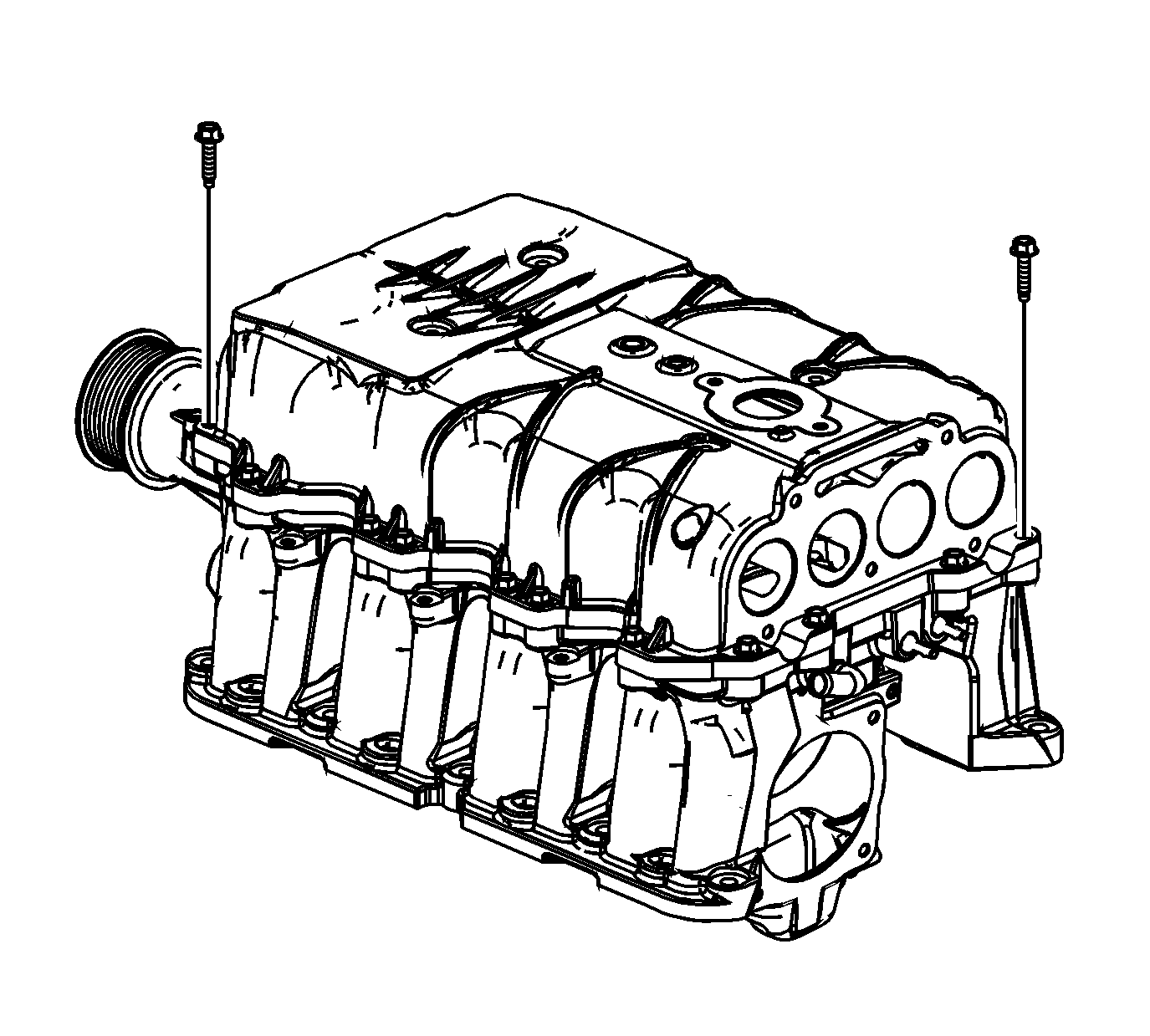
- Remove the long charge air cooler bolts.
- Remove the short charge air cooler perimeter bolts.
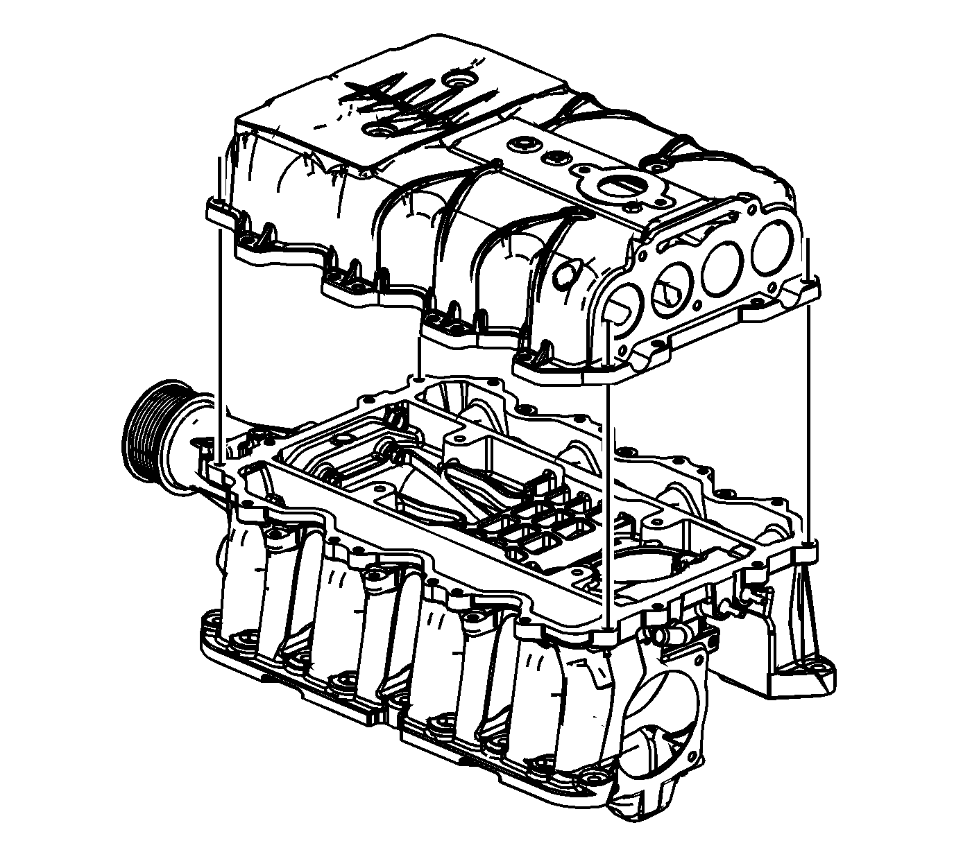
- Remove the charge air cooler housing.
- Remove and discard the charge air cooler housing perimeter gasket.
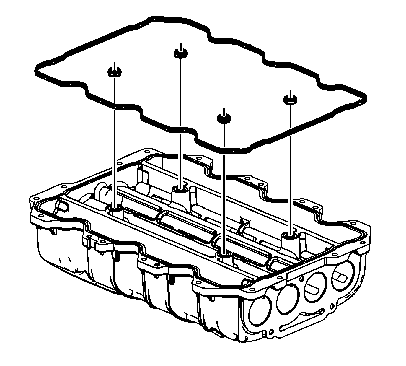
- Remove and discard the charge air cooler housing interior O-ring gaskets.
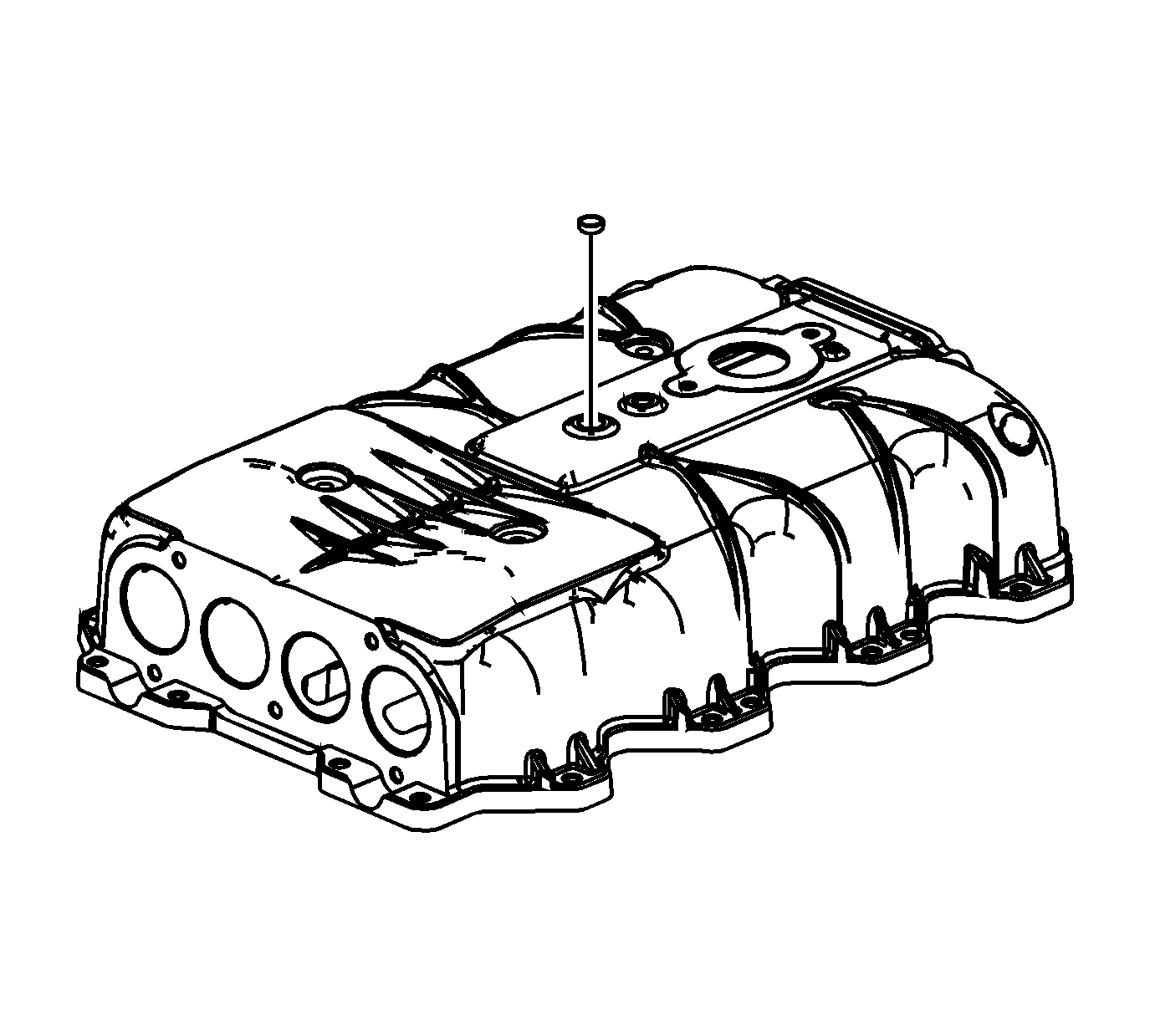
- Remove and discard the charge air cooler housing expansion plug.
Important: In order to protect and service components, on the supercharger, ensure the EN-47833 is on the supercharger during the disassembly and assembly.
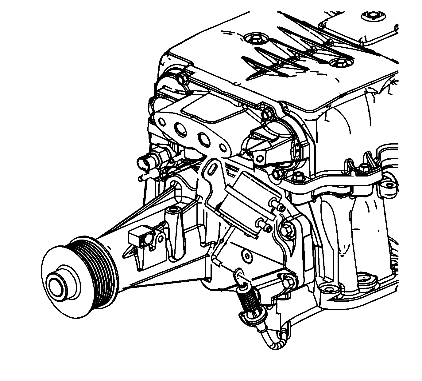
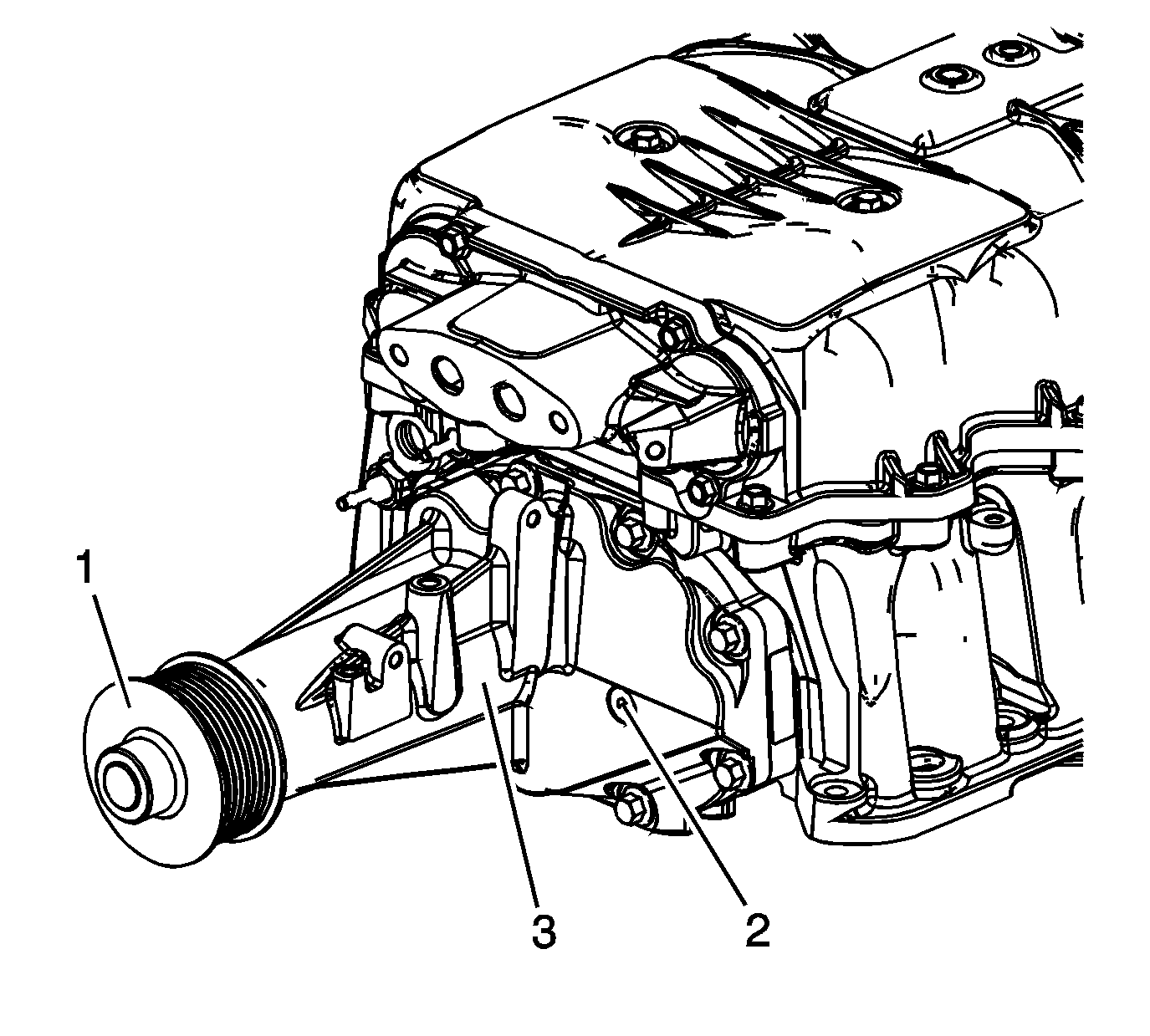
| • | Drive pulley (1) |
| • | Oil level plug (2) |
| • | Front housing (3) |
| • | Bearings |
| • | Rotors |
| • | Gears |
Cleaning Procedure
- Remove any old thread sealant and gasket material or sealant.
- Do NOT soak the supercharger, bypass valve actuator, charge air bypass regulator solenoid valve, EVAP solenoid, bypass cable or throttle body in solvent.
- Carefully clean the outside of the supercharger. Do NOT allow any debris or solvent to enter the inside of the supercharger. Replace the supercharger if there is any damage to the rotors.
- Carefully clean the outside charge air cooler cooling tube. Do NOT allow any debris to enter the inside of the tubes. Replace the tube if there are any damaged, missing or bent fins. Replace the tube if the coolant passages are blocked by debris.
- Clean the charge air cooler housing with solvent compatible with aluminum and the painted exterior. Clean all threaded and through holes with solvent.
- Clean the PCV, vacuum and pressure tubes.
- Carefully dry the components with compressed air.
Important: Do NOT allow any debris to enter the supercharger.
Caution: Refer to Safety Glasses Caution in the Preface section.
Inspection Procedure
- Inspect the interior of the charge air cooler front manifold for the following:
- Inspect the exterior of the charge air cooler front manifold for the following:
- Repair or replace the charge air cooler front manifold as necessary.
- Inspect the interior of the charge air cooler rear manifold for the following:
- Inspect the exterior of the charge air cooler rear manifold for the following:
- Repair or replace the charge air cooler rear manifold as necessary.
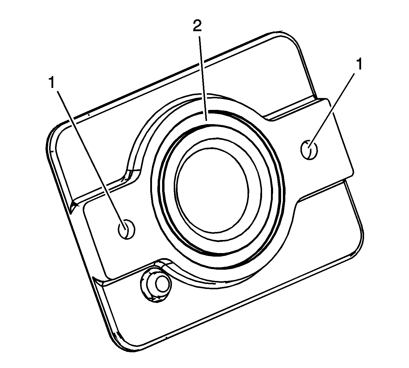
- Inspect the charge air cooler cooling fill cap for damage or corrosion (1, 2).
- Repair or replace the charge air cooler cooling fill cap as necessary.
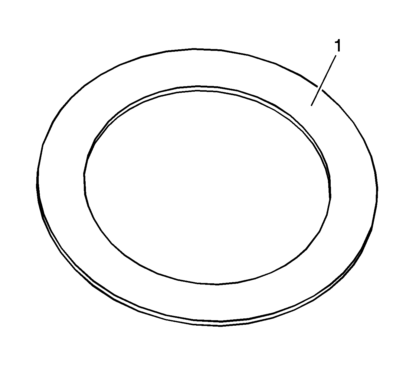
- Inspect the charge air cooler cooling tube spacers for damage or corrosion (1).
- Replace any damaged charge air cooler cooling tube spacers.
- Inspect the charge air cooler cooling tubes for the following:
- Inspect the charge air cooler cooling tubes for the following:
- Replace any damaged, corroded or restricted charge air cooler cooling tube.
- Inspect the charge air cooler housing for the following:
- Inspect the charge air cooler housing for the following:
- Inspect the interior of the charge air cooler housing for the following:
- Repair or replace the charge air cooler housing as necessary.
- Inspect the PCV, vacuum and pressure tubes for damage. Replace as necessary.
- Inspect the supercharger perimeter sealing surface (1) for the charge air cooler housing for damage.
- Inspect the bottom of the supercharger for the following:
- Inspect the interior of the supercharger for the following:
- Inspect the supercharger for the following:
- Inspect the supercharger for the following:
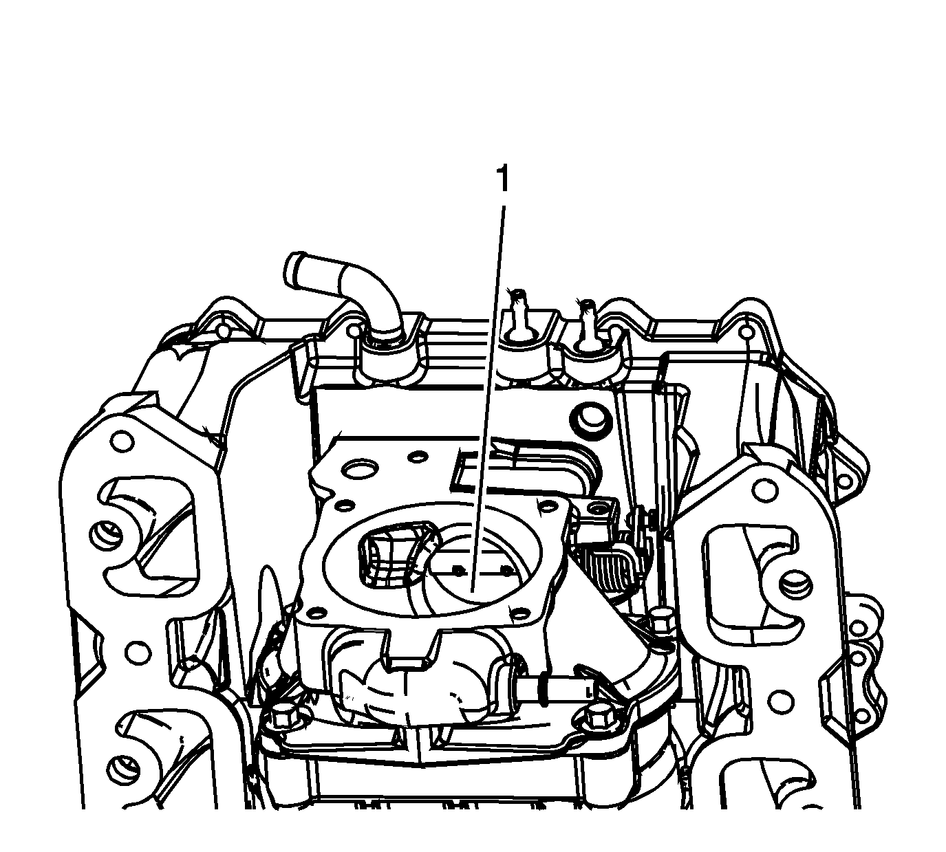
- Inspect the bypass valve for the following:
- Inspect the bypass valve (1) to ensure the valve is closing.
- Do NOT attempt to repair the supercharger or the bypass valve. The supercharger and bypass valve are replaced as an assembly.
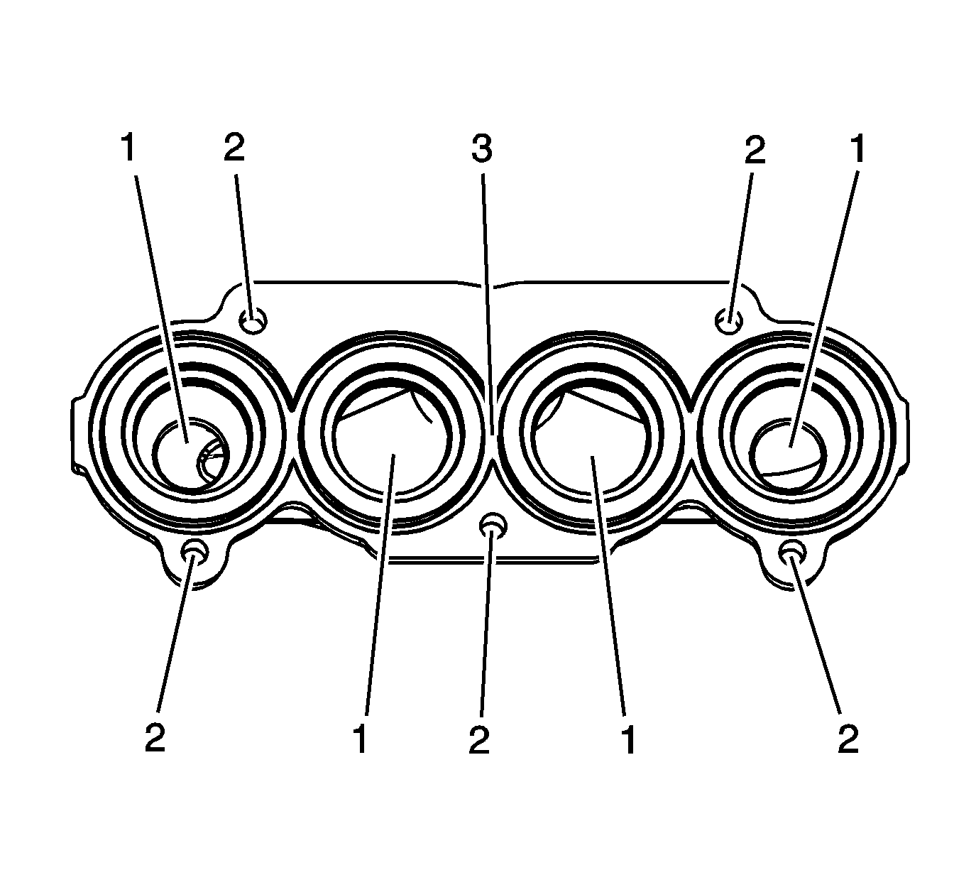
| • | Damage or restrictions to the coolant passages (1) |
| • | Damage to the bolt bosses (2) |
| • | Damage or corrosion to the gasket groove (3) |
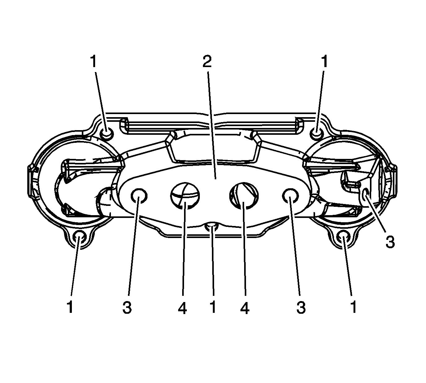
| • | Damage to the bolt bosses (1) |
| • | Damage or corrosion to the gasket sealing surface (2) |
| • | Damage to the threaded holes (3) |
| • | Damage or restrictions to the coolant passages (4) |
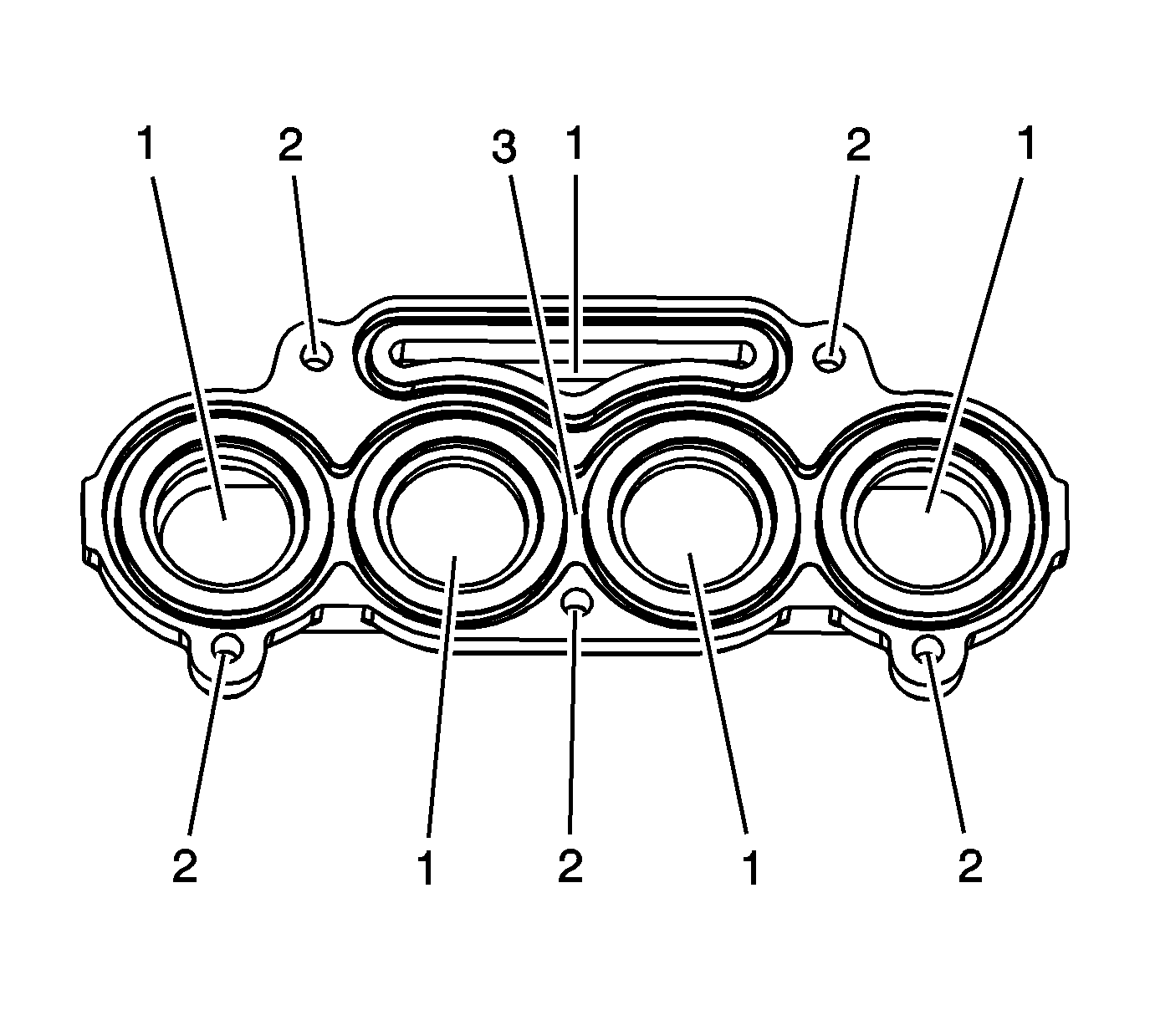
| • | Damage or restrictions to the coolant passages (1) |
| • | Damage to the bolt bosses (2) |
| • | Damage or corrosion to the gasket groove (3) |
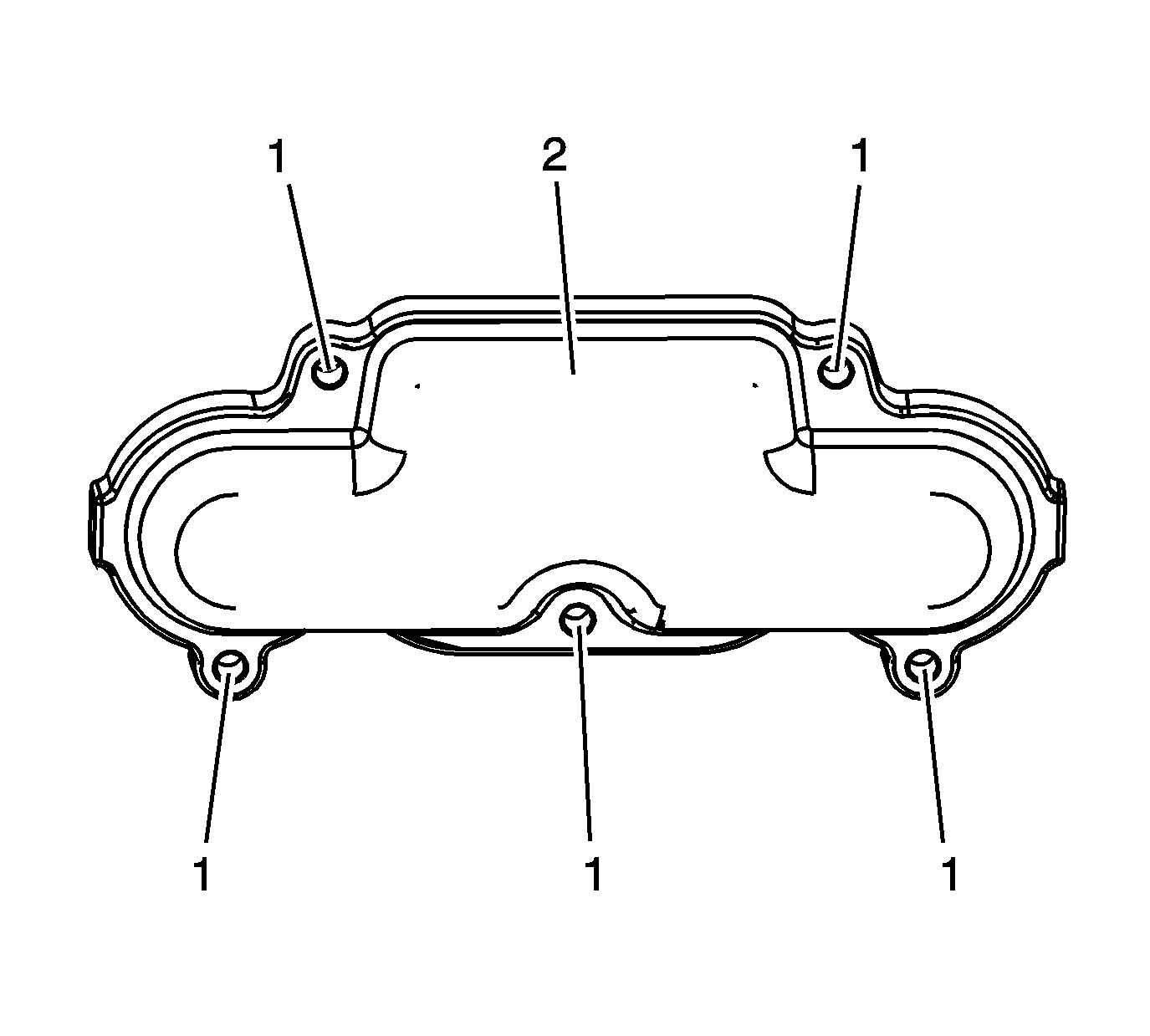
| • | Damage to the bolt bosses (1) |
| • | Damage or corrosion to the charge air cooler rear manifold (2) |
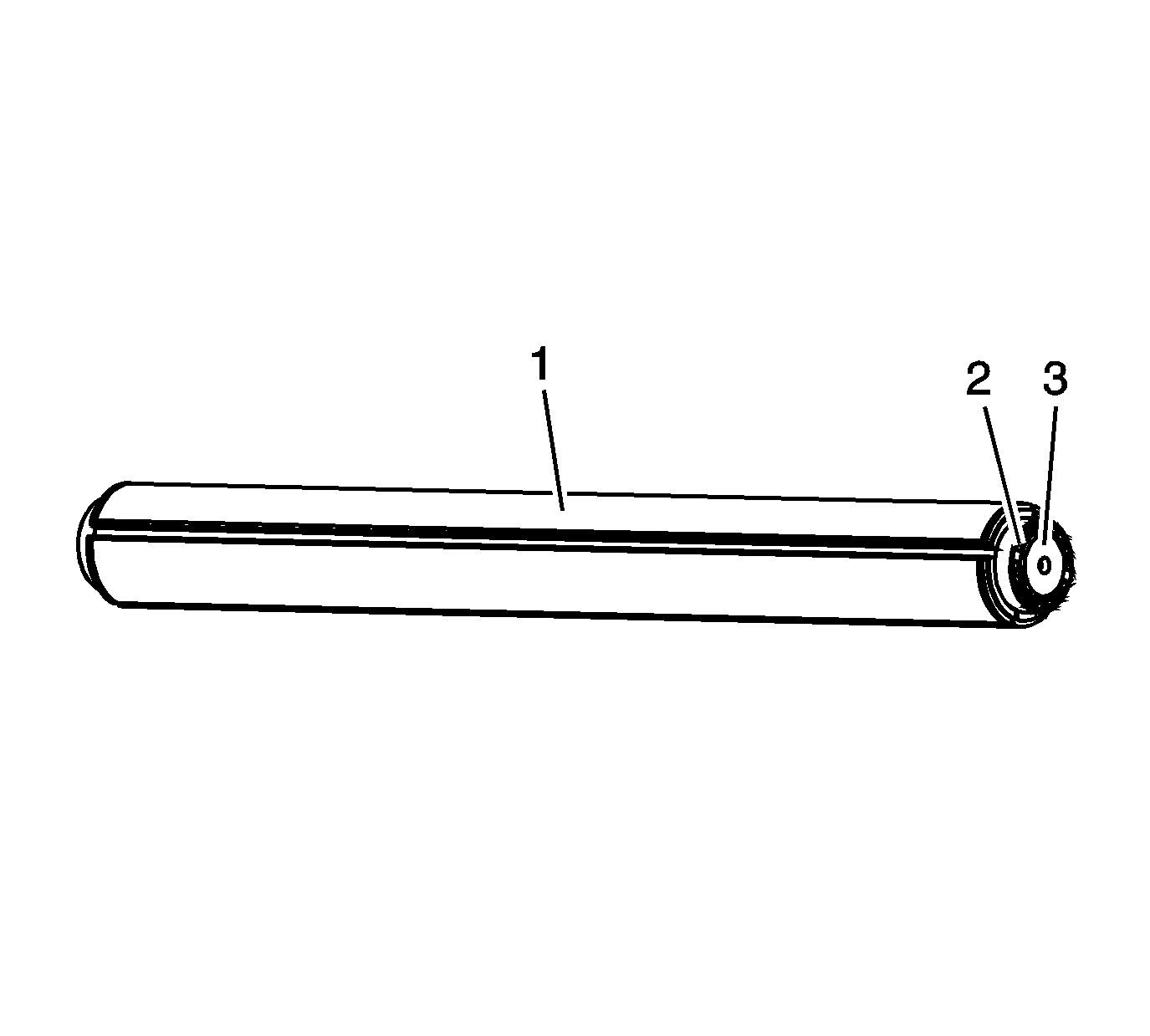
| • | Damaged, clogged, bent or missing fins (1) |
| • | Damage, corrosion or restrictions to the cooling passages (2) |
| • | Damage, corrosion, restrictions or missing diversion end plate (3) |
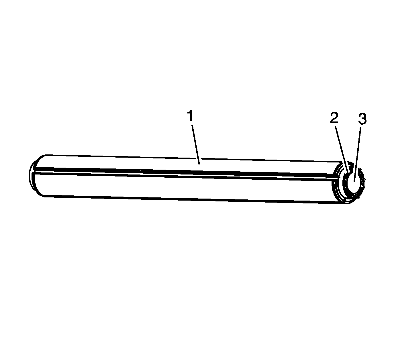
| • | Damaged, clogged, bent or missing fins (1) |
| • | Damage, corrosion or restrictions to the cooling passages (2) |
| • | Damage, corrosion or restrictions to the intake end (3) |
Important: The charge air cooler cooling tubes are replaced as a set. If any one of the charge air cooler cooling tubes needs to be replaced, all the charge air cooler cooling tubes must be replaced in order to maintain consistent cooling of the charge air.
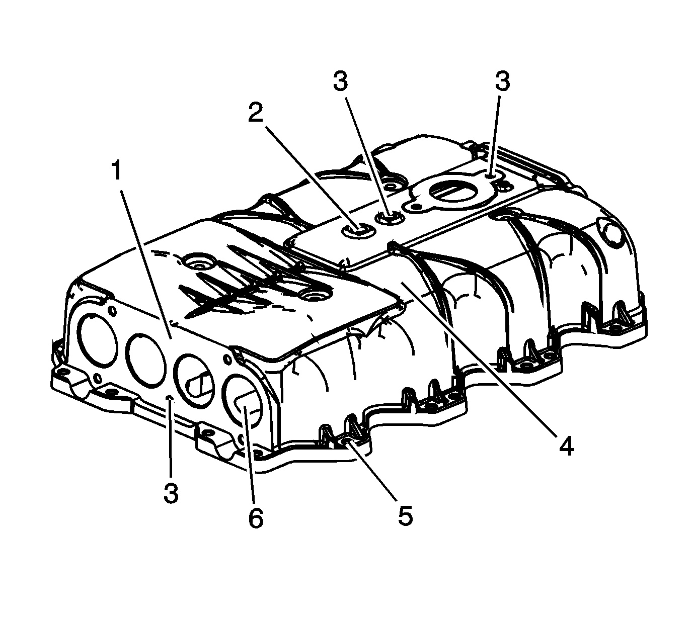
| • | Damage to the sealing surface (1) for the charge air cooler front manifold |
| • | Damage to the bore (2) for the charge air cooler housing expansion plug |
| • | Damage to the threaded holes (3) |
| • | Damage to the exterior of the charge air cooler housing (4) |
| • | Damage to the bolt bosses (5) |
| • | Damage, corrosion, restrictions in the bores (6) for the charge air cooler cooling tubes |
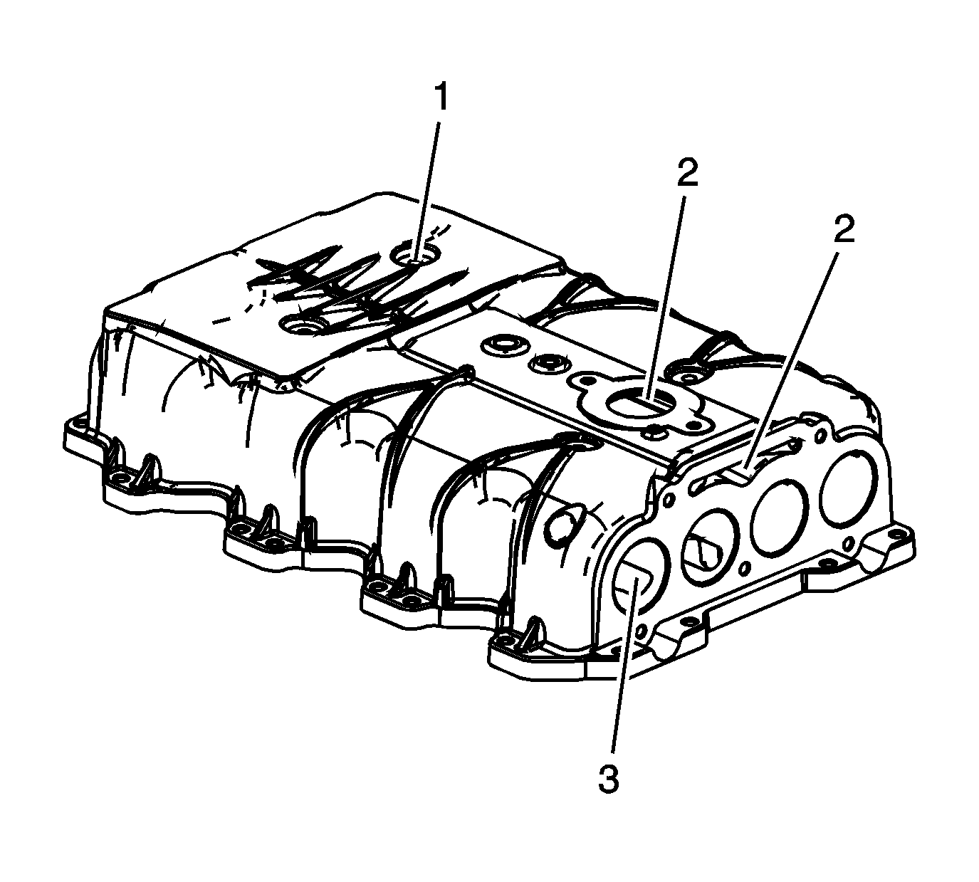
| • | Damage to the bolt bosses (1) |
| • | Damage, corrosion, restrictions in the coolant passages (2) |
| • | Damage, corrosion, restrictions in the bores (3) for the charge air cooler cooling tubes |
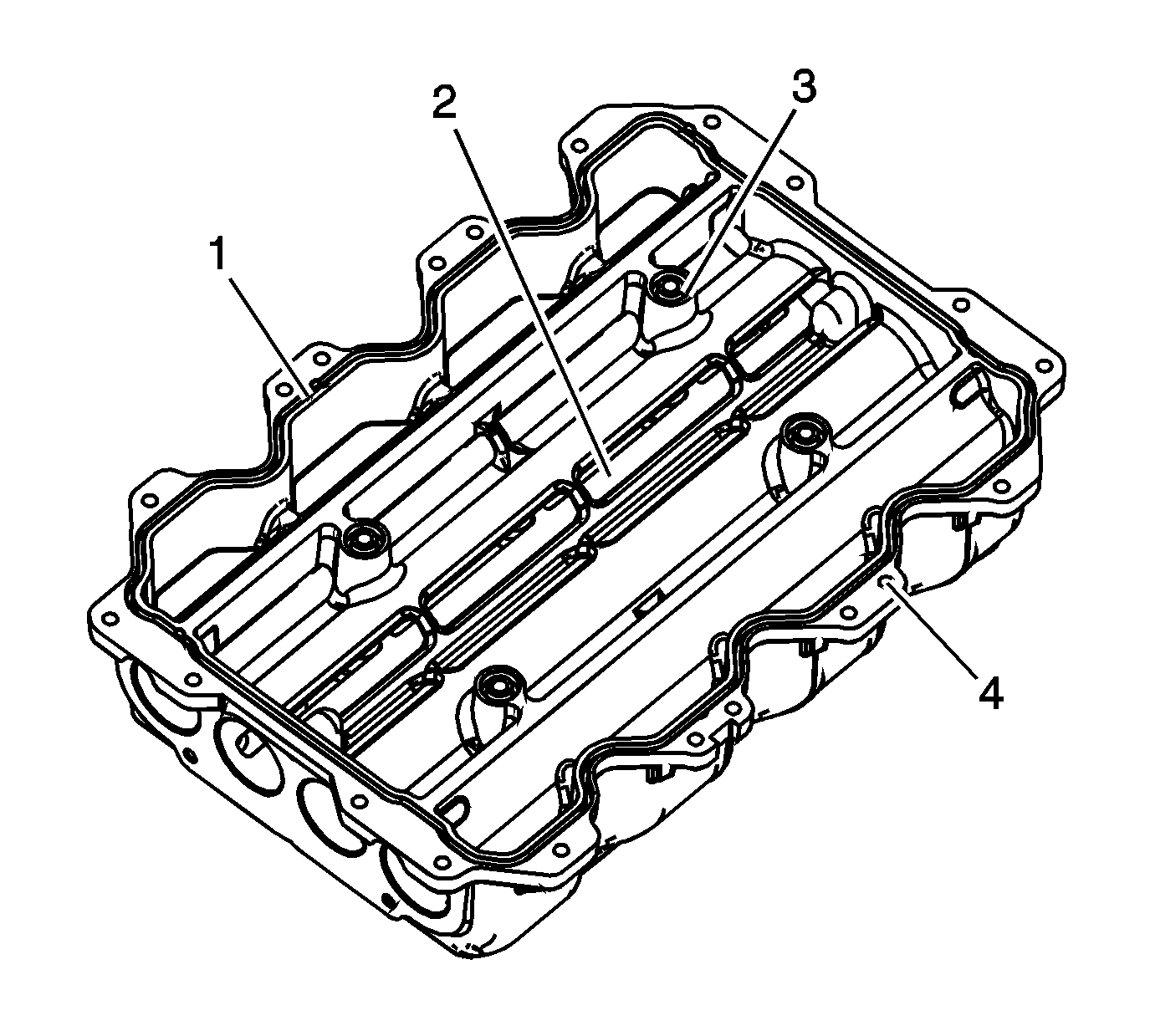
| • | Damage to the sealing grooves for the perimeter gasket (1) |
| • | Damage, corrosion or restrictions in the passages (2) for the charge air cooler cooling tubes |
| • | Damage to the sealing grooves for the interior O-ring gaskets (3) |
| • | Damage to the bolt bosses (4) |
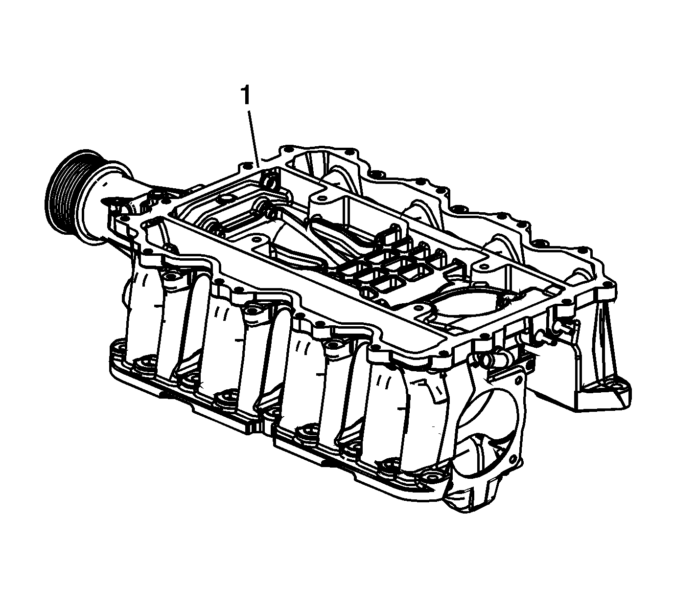
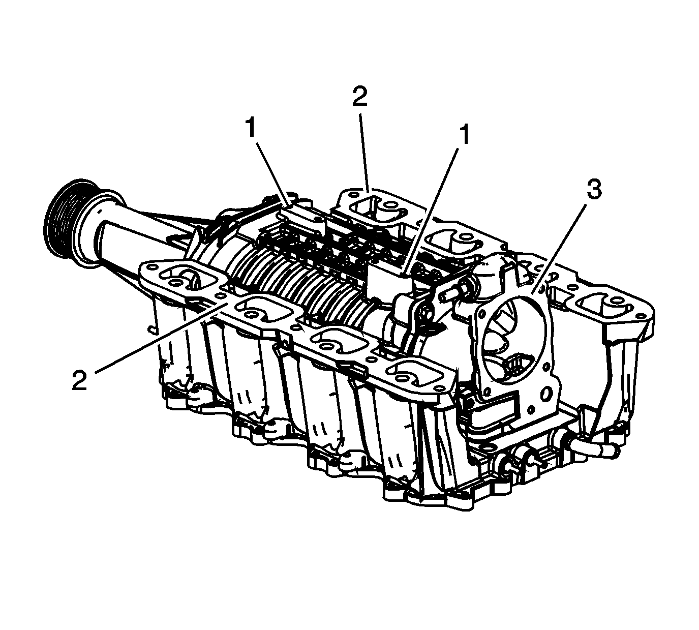
| • | Damage to the threaded holes (1) |
| • | Damage to the supercharger gasket sealing surface (2) |
| • | Damage to the throttle body gasket sealing surface (3) |
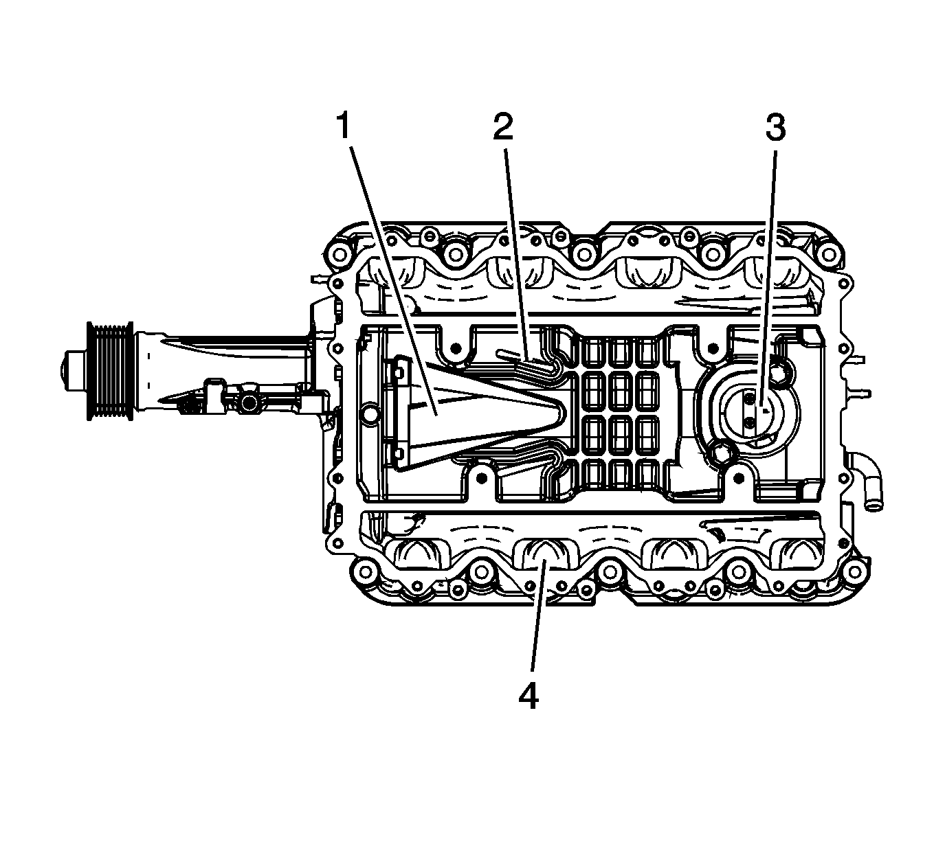
| • | Damage to the supercharger rotors (1) |
| • | Restrictions in the charge air passages (2) |
| • | Damage or restrictions in the passages (3) for bypass valve |
| • | Damage or restrictions in the intake passages (4) |
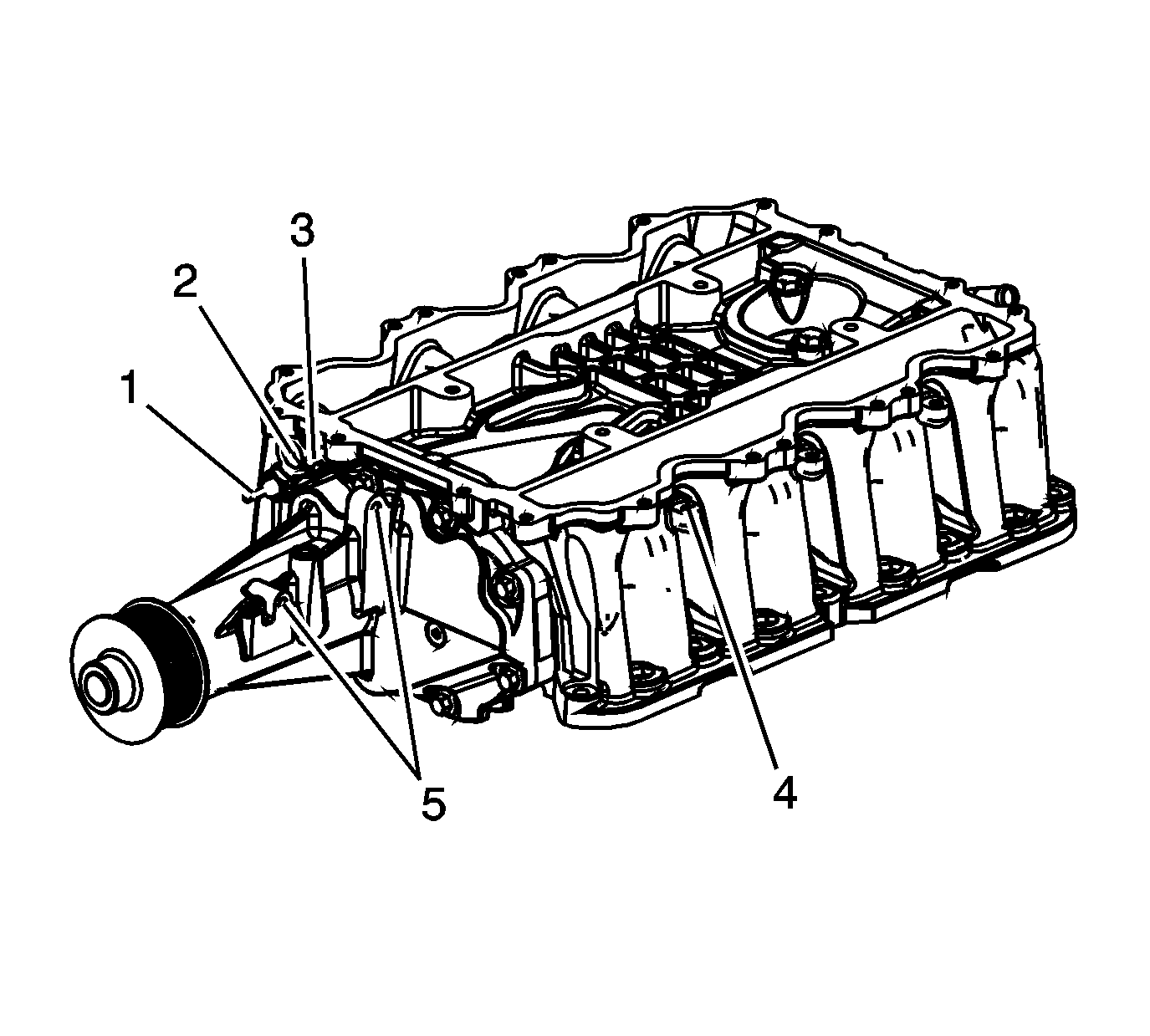
| • | Damage or restrictions to the port (1) for the manifold absolute pressure (MAP) sensor |
| • | Damage or restrictions in the IAT sensor 2 threaded hole (2) |
| • | Damage or restrictions to the pressure port (3) for the charge air bypass regulator solenoid valve tube |
| • | Damage to the threaded holes (4) for the fuel rail mounting studs |
| • | Damage to the threaded holes (5) for the bypass actuator valve |
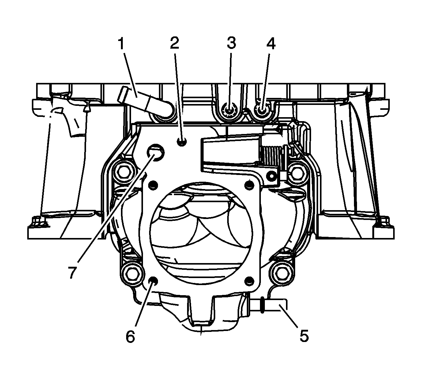
| • | Damage or restrictions to the port (1) for the brake booster hose |
| • | Damage to the threaded hole (2) for the EVAP solenoid bolt |
| • | Damage or restrictions to the port (3) for the bypass actuator tube. |
| • | Damage or restrictions to the port (4) for the supercharger inlet absolute pressure sensor tube |
| • | Damage or restrictions to the port (5) for the PCV dirty air tube |
| • | Damage to the threaded holes (6) for the throttle body bolts |
| • | Damage or restrictions to the port (7) for the EVAP canister purge solenoid valve |
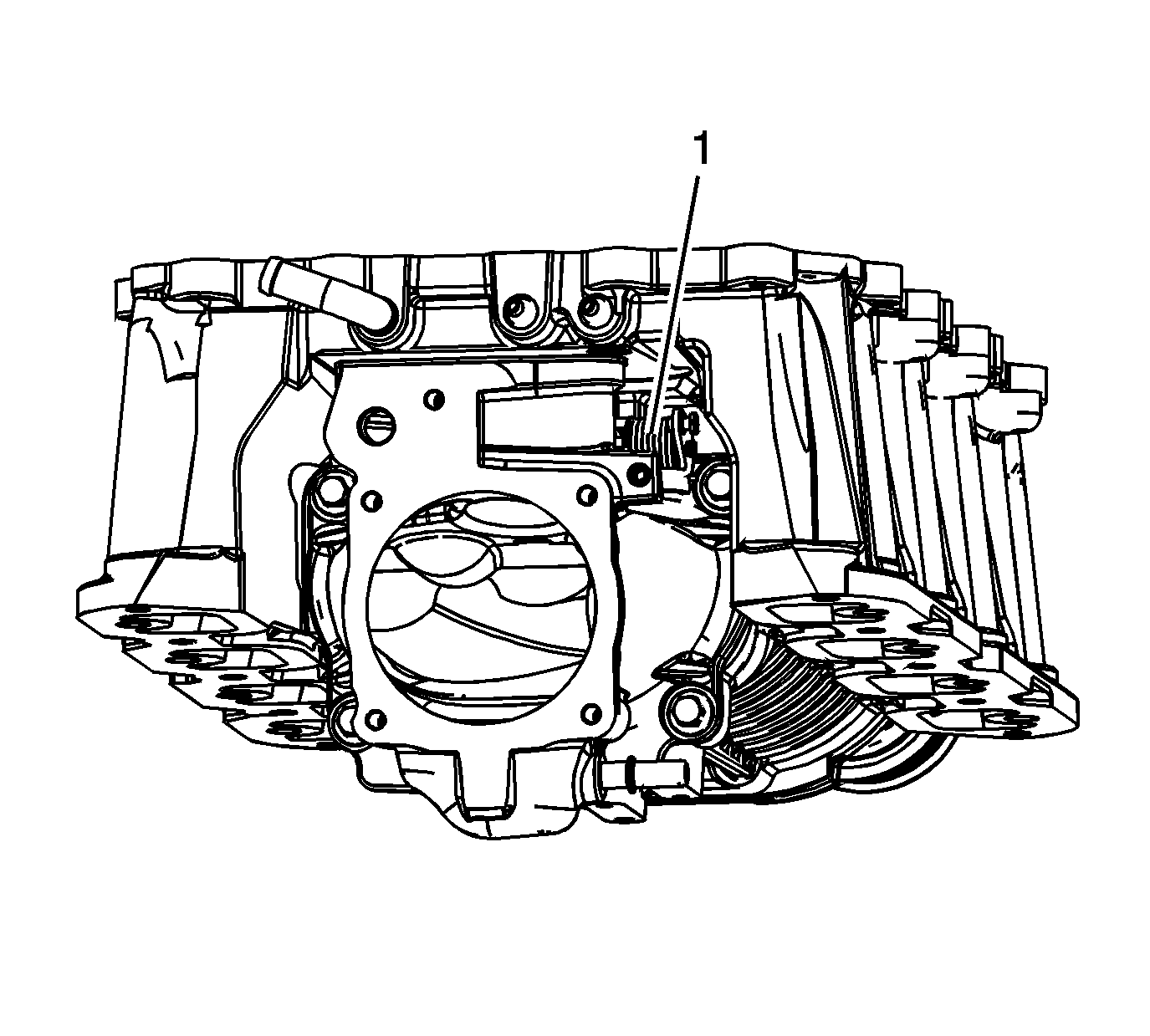
| • | Rotate the bypass valve to ensure the bypass valve does not bind during opening |
| • | Ensure the spring (1) closes the bypass valve |
Assemble Procedure
- Install the NEW charge air cooler housing expansion plug.
- Install the NEW charge air cooler housing interior O-ring gaskets.
- Install the NEW charge air cooler housing perimeter gasket.
- Install the charge air cooler housing.
- Install the long charge air cooler bolts.
- Install the short charge air cooler perimeter bolts.
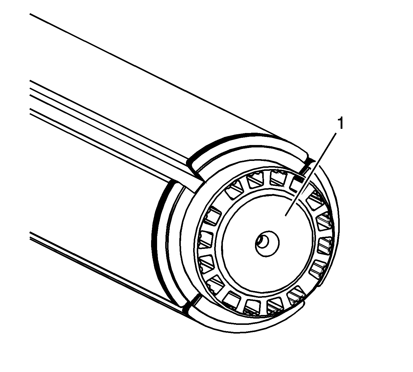
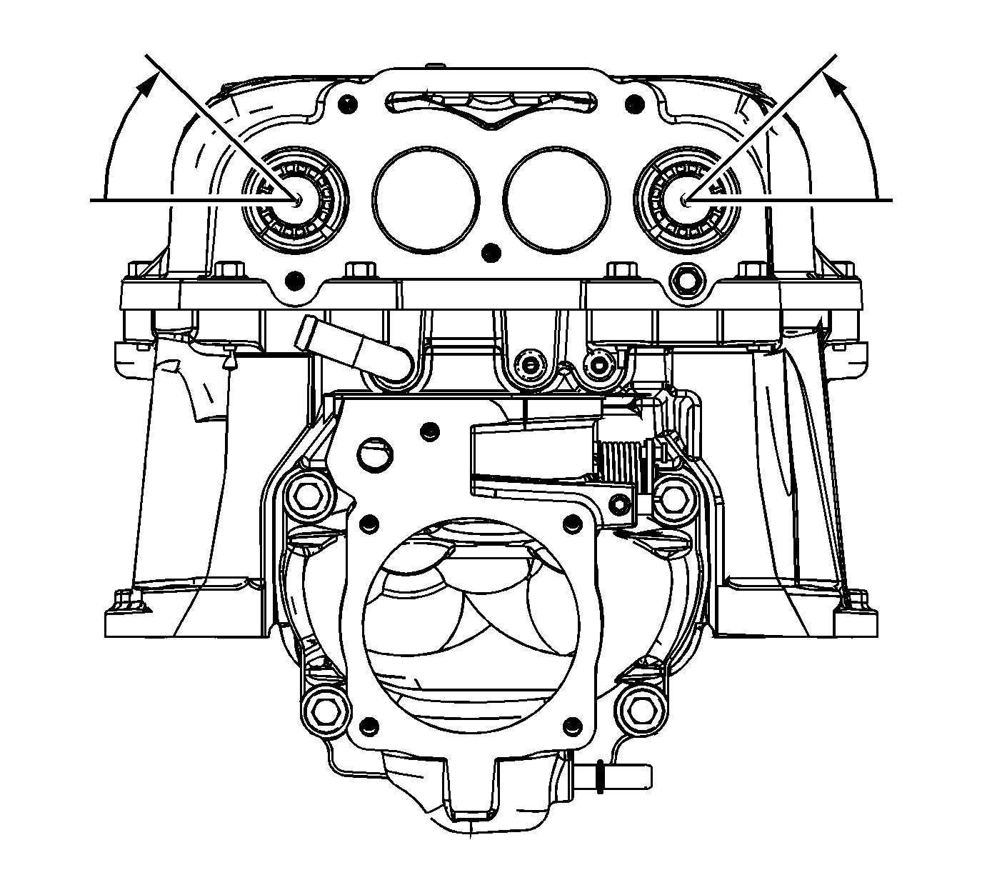
- Carefully install the outboard charge air cooler cooling tubes.
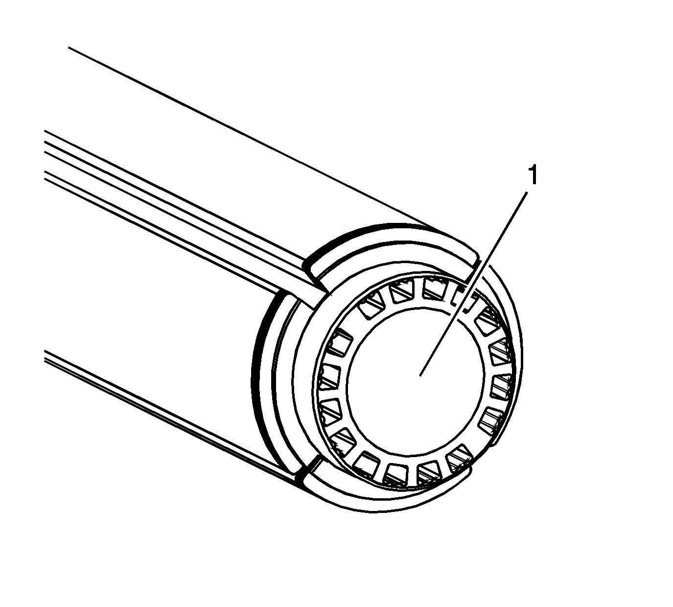
- The charge air cooler cooling outboard tubes are installed with the restrictor plates (1) to the back of the manifold, away from the drive belt pulley.
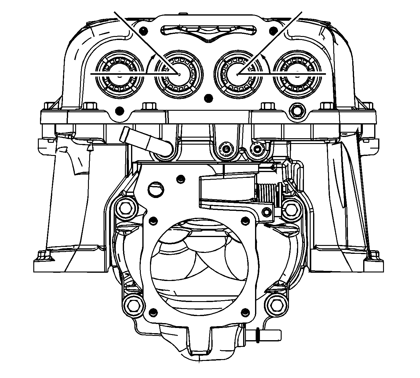
- Align the wide notch at a 45 degree angle up from horizontal and outboard as shown.
- Carefully install the inboard charge air cooler cooling tubes.
- The charge air cooler cooling inboard tubes are installed with the opening (1) to the back of the manifold. The restrictor plates will be to the front of the manifold, towards the drive belt pulley.
- Align the wide notch at a 45 degree angle up from horizontal and outboard as shown.
- Install the NEW charge air cooler cooling fill cap O-ring.
- Install the charge air cooler cooling fill cap.
- Ensure the charge air cooler cooling fill cap is installed in the proper orientation.
- Install the charge air cooler cooling fill cap bolts.
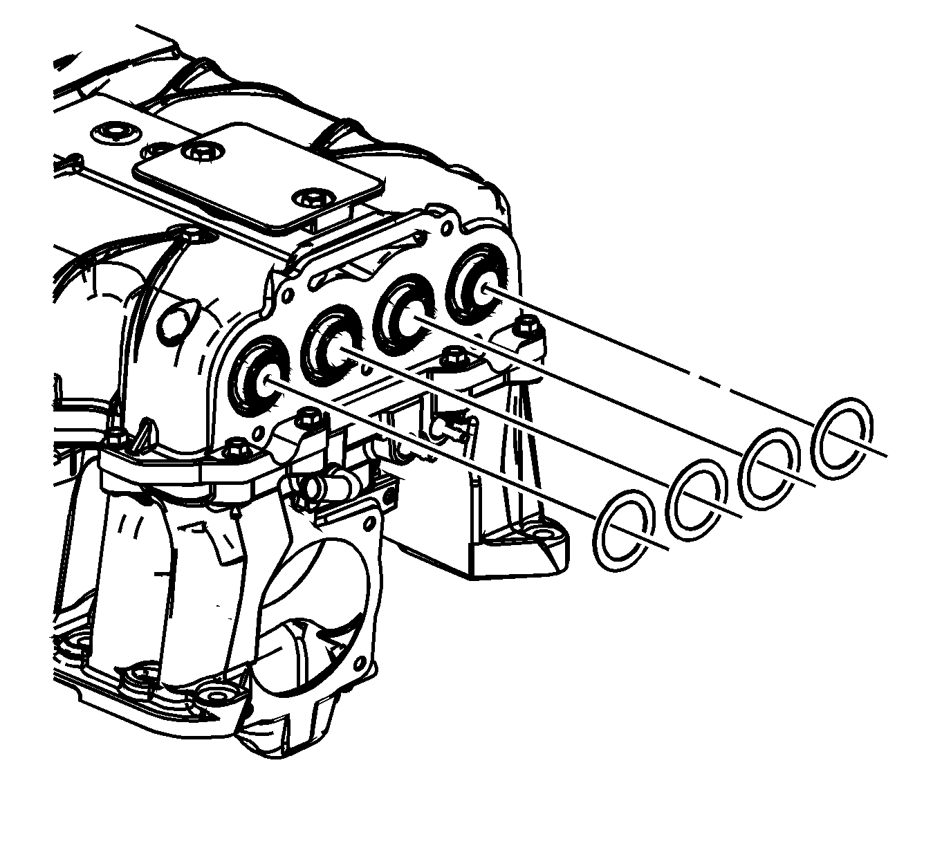
- Install the charge air cooler cooling tube rear spacers.
- Install the NEW charge air cooler cooling tube rear O-rings.
- Install the NEW charge air cooler rear manifold gaskets.
- Install the charge air cooler rear manifold.
- Install the charge air cooler rear manifold bolts.
- Install the charge air cooler cooling tube front spacers.
- Install the NEW charge air cooler cooling tube front O-rings.
- Install the NEW charge air cooler front manifold gasket.
- Install the charge air cooler front manifold.
- Install the charge air cooler front manifold bolts.
- Coat the IAT sensor 2 threads with sealant GM P/N 12346004 (Canadian P/N 10953480), or equivalent.
- Install the IAT sensor 2 into the supercharger.
- Install the fuel injection fuel rail crossover tube clip.
- Install the bypass valve actuator cable.
- Install the bypass valve actuator cable bracket bolts to the supercharger.
- Slide the bypass valve actuator cable clip onto the pin on the supercharger bypass valve.
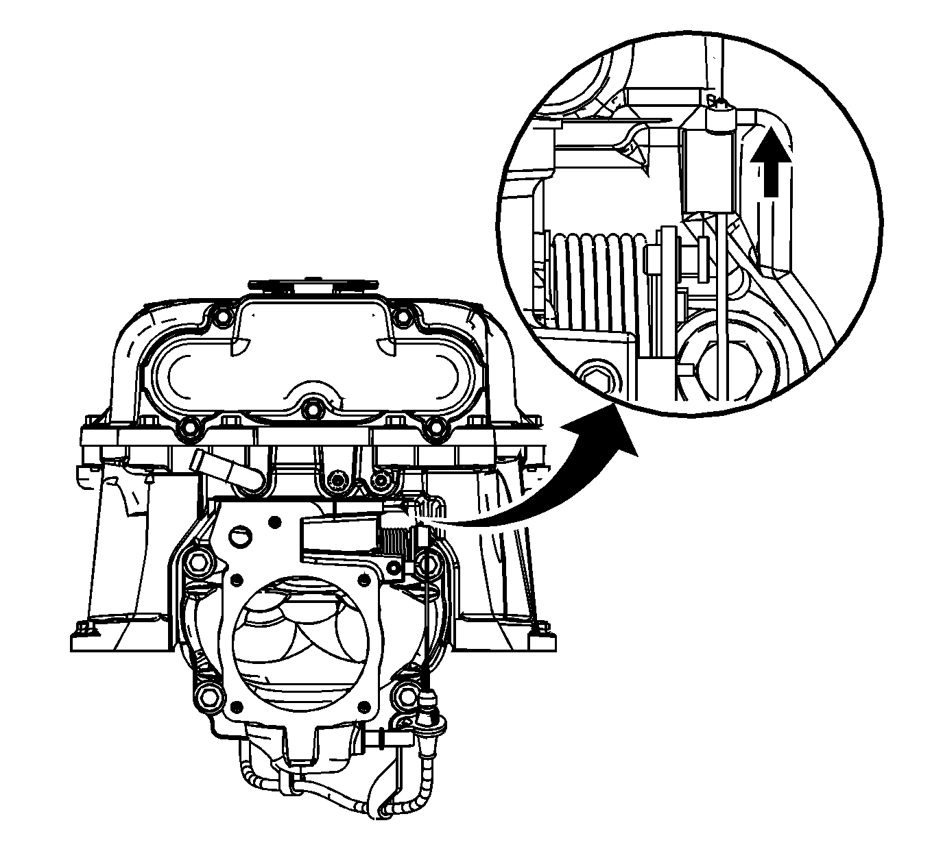
- Pull the retainer up on the wire above the bypass valve actuator cable clip in order to install the EN-47814 . The EN-47814 must be used to set the necessary slack in the bypass valve actuator cable.
- Place the EN-47814 on the cable.
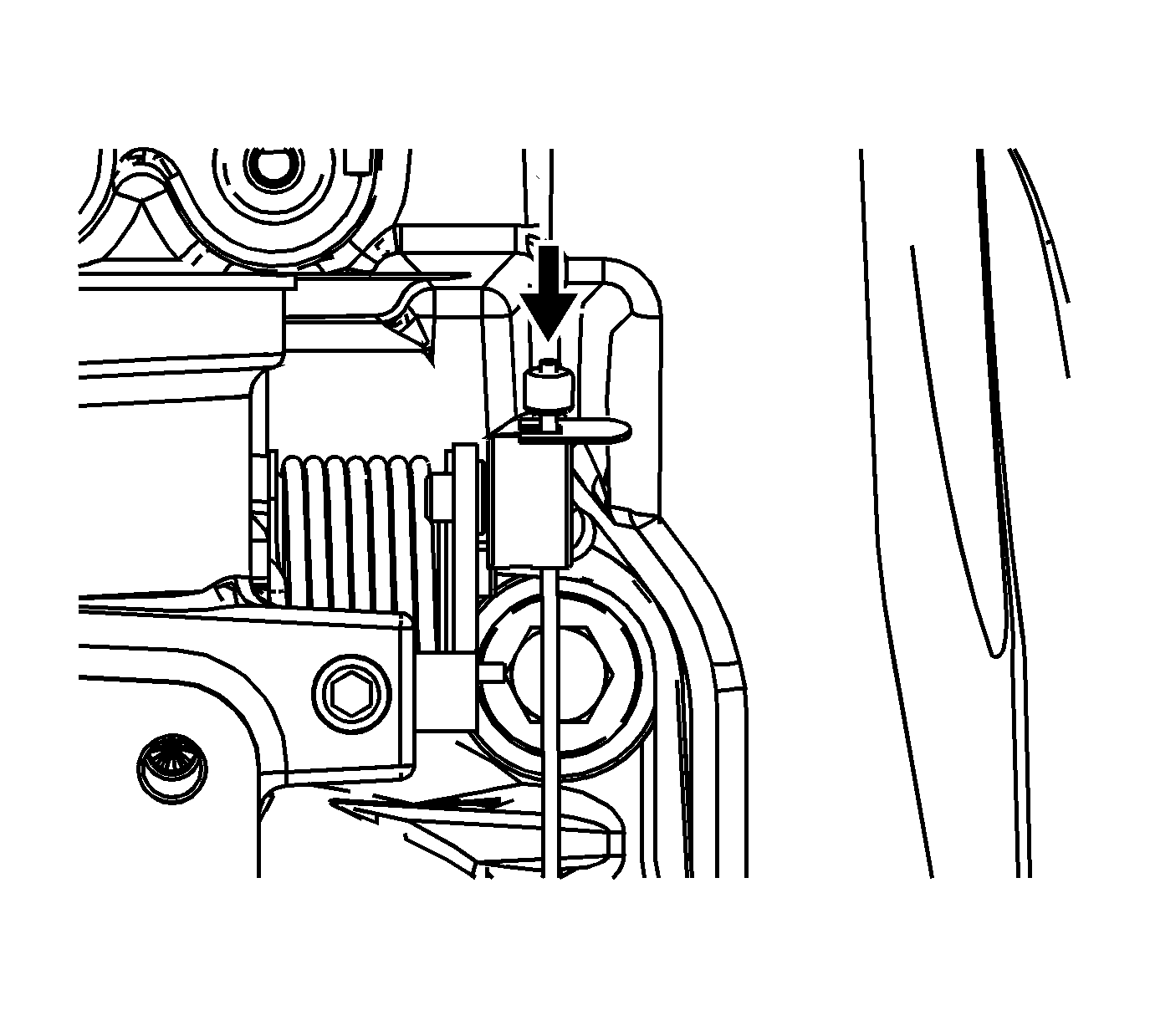
- Ensure to eliminate the slack in the bypass valve actuator cable by pressing down on the wire retainer.
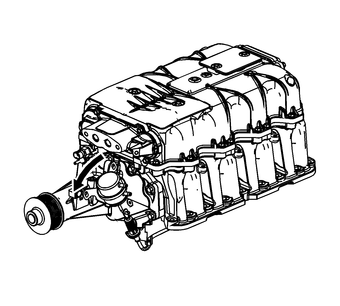
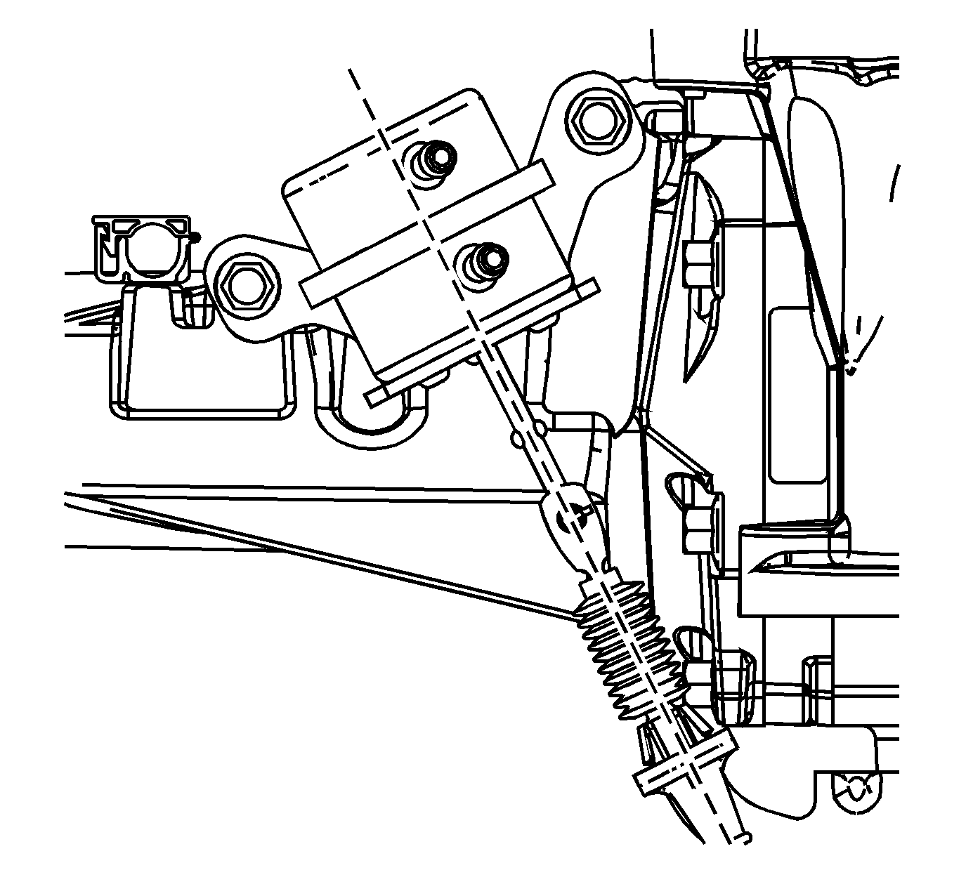
- Install the bypass valve actuator.
- Align the bypass valve actuator rod to the bypass valve actuator cable.
- Align the tab on the bypass valve actuator rod with the slot in the bypass valve actuator cable end.
- Slide the bypass valve actuator rod into the bypass valve actuator cable.
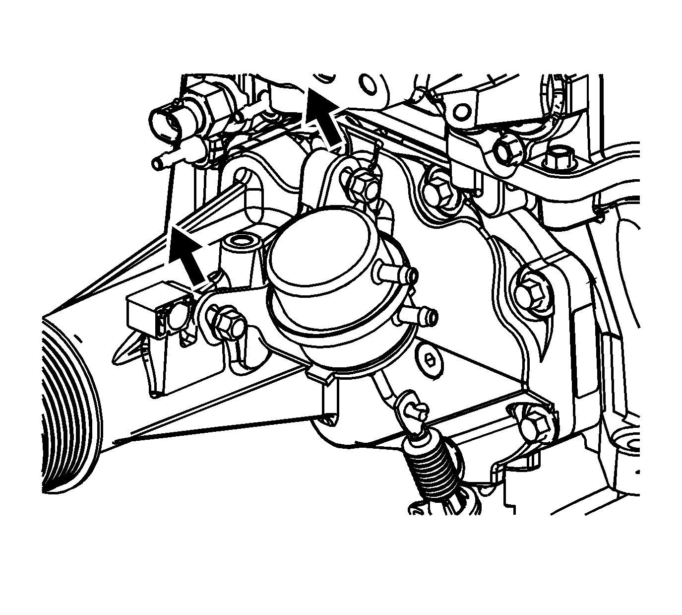
- Pivot the bypass valve actuator counterclockwise in order to install bypass valve actuator.
- Loosely install the bypass valve actuator bolts.
- Pull up on the bypass valve actuator in order to eliminate any slack in the bypass valve actuator cable.
- Tighten the bypass valve actuator bolts while maintaining proper alignment between the bypass valve actuator and the bypass valve actuator cable.
- Remove the EN-47814 on the bypass valve actuator cable at the bypass valve.
- Install the charge air bypass regulator solenoid valve.
- Install the charge air bypass regulator solenoid valve bolt.
- Install the charge air bypass regulator solenoid valve pressure hose.
- Connect the charge air bypass regulator solenoid valve pressure hose at the supercharger pressure port (1).
- Connect the charge air bypass regulator solenoid valve pressure hose at the upper port of the charge air bypass regulator solenoid valve (2).
- Install the bypass valve actuator pressure hose.
- Connect the bypass valve actuator pressure hose at the lower port of the supercharger bypass valve actuator (1).
- Connect the bypass valve actuator pressure hose at the lower port of the charge air bypass regulator solenoid valve (2).
- Install the bypass valve actuator vacuum hose to the supercharger.
- Connect the bypass valve actuator vacuum hose at the upper port of the supercharger bypass valve actuator (1).
- Connect the bypass valve actuator vacuum hose at the center small vacuum port of the supercharger (1).
- Install the NEW throttle body O-ring.
- Install the throttle body.
- Install the throttle body bolts.
- Install the NEW O-ring onto the EVAP canister purge solenoid valve.
- Install the EVAP canister purge solenoid valve.
- Install the EVAP canister purge solenoid valve bolt.
- Install and connect the dirty air PCV tube onto the supercharger.
Important: In order to protect and service components, on the supercharger, ensure the EN-47833 is on the supercharger during the disassembly and assembly.


Notice: Refer to Fastener Notice in the Preface section.

Tighten
Tighten the long charge air cooler bolt to 10 N·m (89 lb in).

Tighten
Tighten the short charge air cooler bolt to 10 N·m (89 lb in).

Important: The charge air cooler cooling tubes are replaced as a set. If any one of the charge air cooler cooling tubes needs to be replaced, all the charge air cooler cooling tubes must be replaced in order to maintain consistent cooling of the charge air.

Important: The charge air cooler cooling tubes are replaced as a set. If any one of the charge air cooler cooling tubes needs to be replaced, all the charge air cooler cooling tubes must be replaced in order to maintain consistent cooling of the charge air.


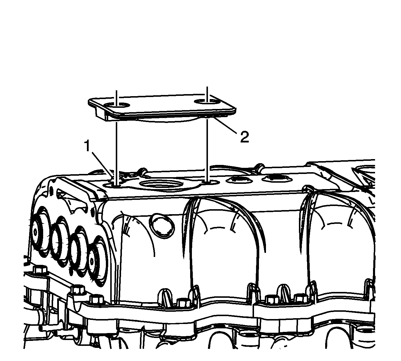
| • | The alignment boss (1) is at the rear of the charge air cooler manifold |
| • | The alignment boss (2) is at the front of the charge air cooler cooling fill cap |

Tighten
Tighten the charge air cooler cooling fill cap bolt to 10 N·m (89 lb in).


Tighten
Tighten the charge air cooler rear manifold bolt to 10 N·m (89 lb in).


Tighten
Tighten the charge air cooler front manifold bolt to 10 N·m (89 lb in).

Tighten
Tighten the IAT sensor 2 to 20 N·m (15 lb ft).


Tighten
Tighten the bypass valve actuator cable bracket bolt to 10 N·m (89 lb in).
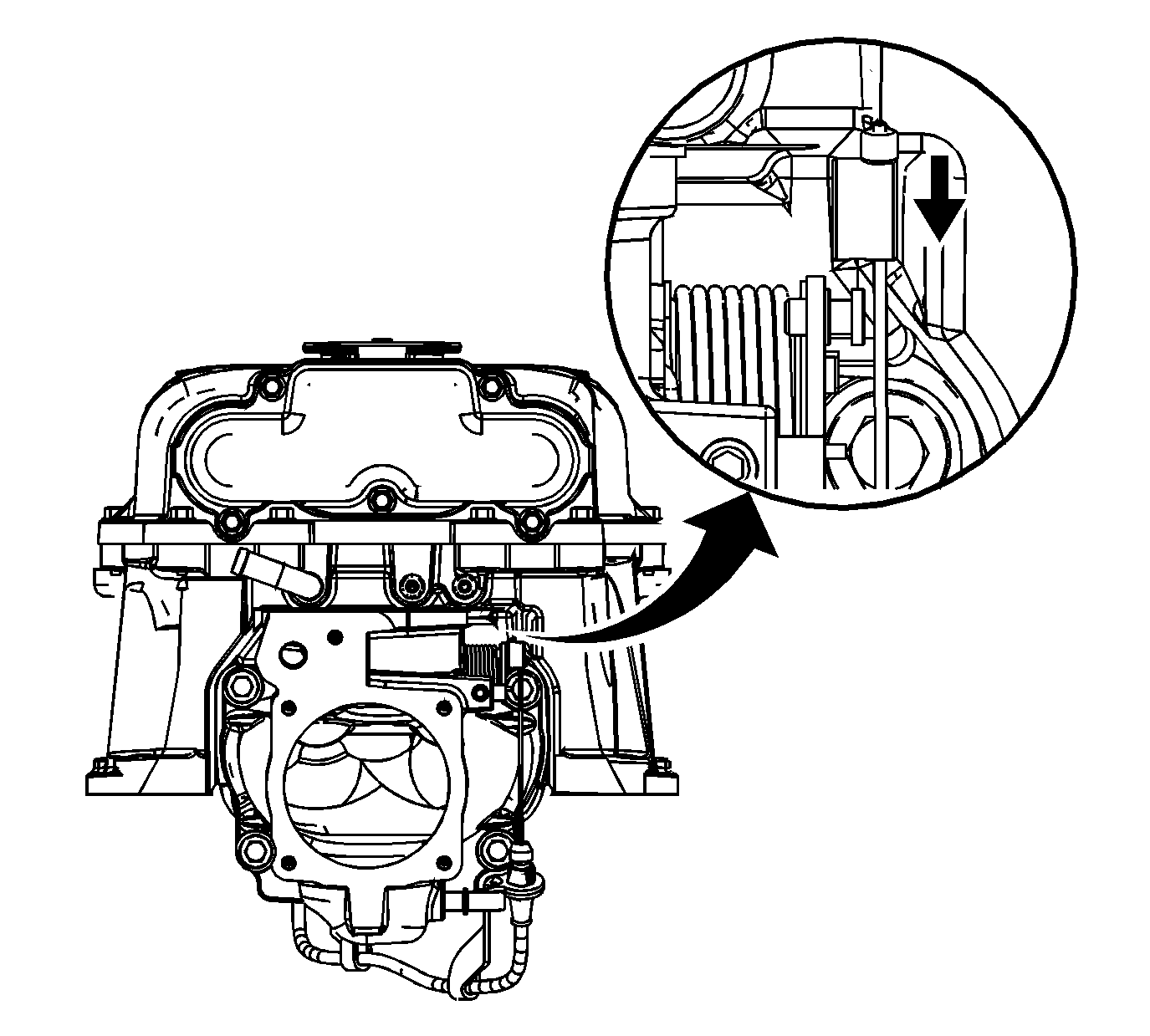
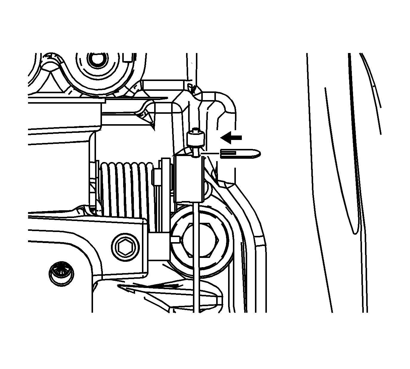
Important: Tool shown is the clip shipped with a new bypass valve actuator cable. The flat end of the EN-47814 can be used for the same purpose.



Tighten
Tighten the bypass valve actuator bolt to 10 N·m (89 lb in).
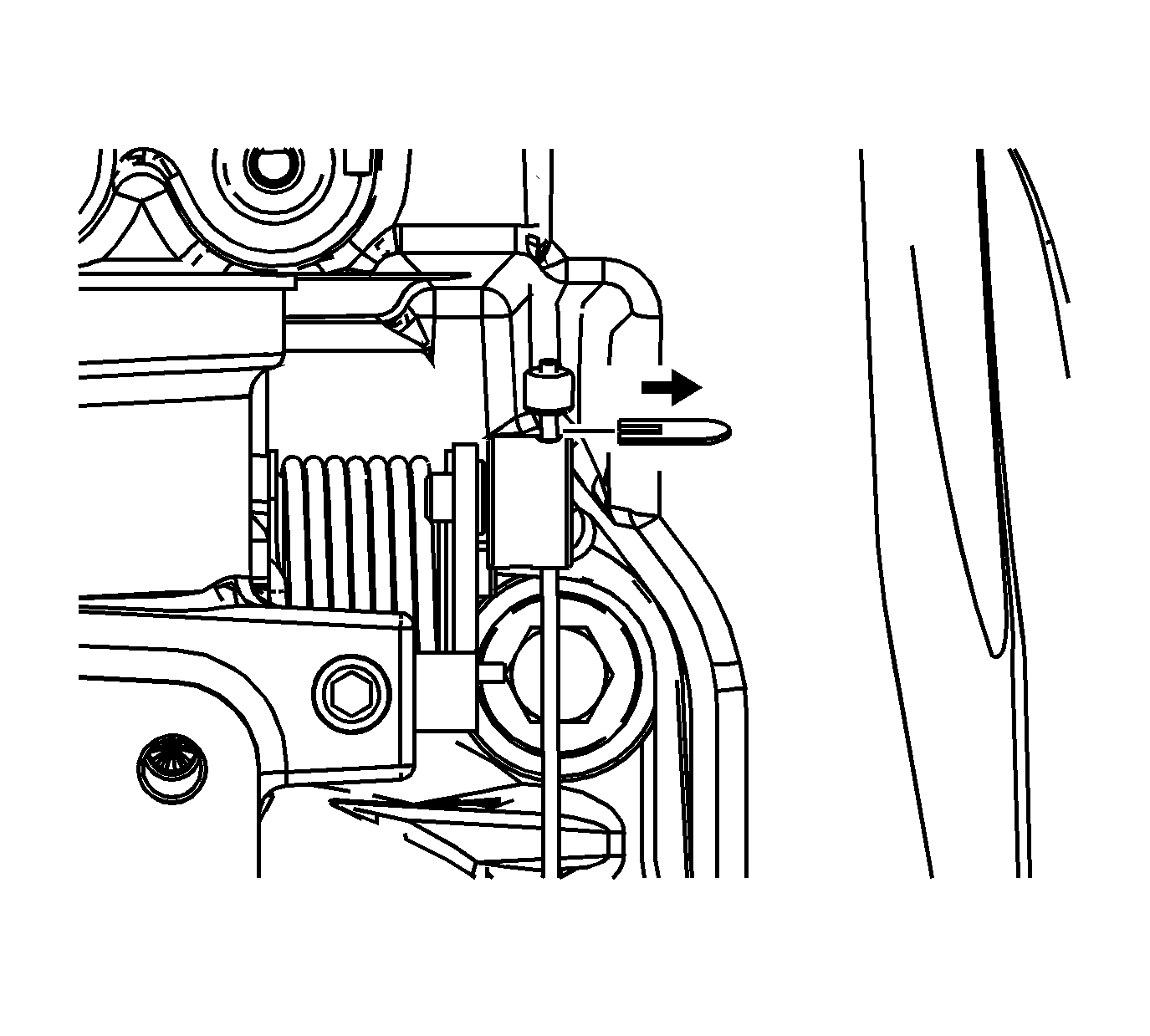
Important: Tool shown is the clip shipped with a new bypass valve actuator cable. The flat end of the EN-47814 can be used for the same purpose.

Tighten
Tighten the charge air bypass regulator solenoid valve bolt to 10 N·m (89 lb in).


Tighten
Tighten the throttle body bolt to 10 N·m (89 lb in).


Tighten
Tighten the EVAP canister purge solenoid valve bolt to 10 N·m (89 lb in).

