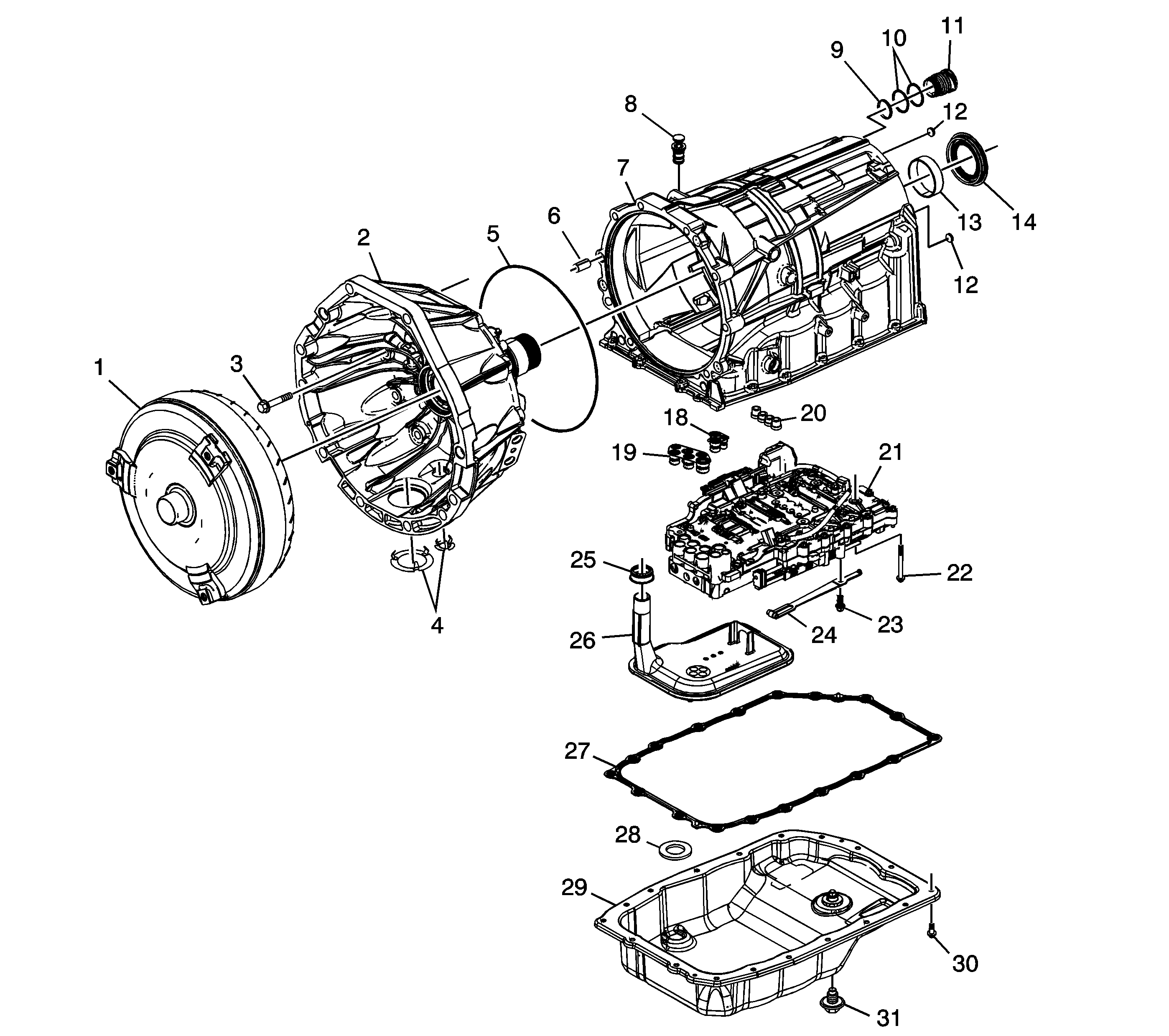
| Figure 1: |
Case and Associated Parts
|
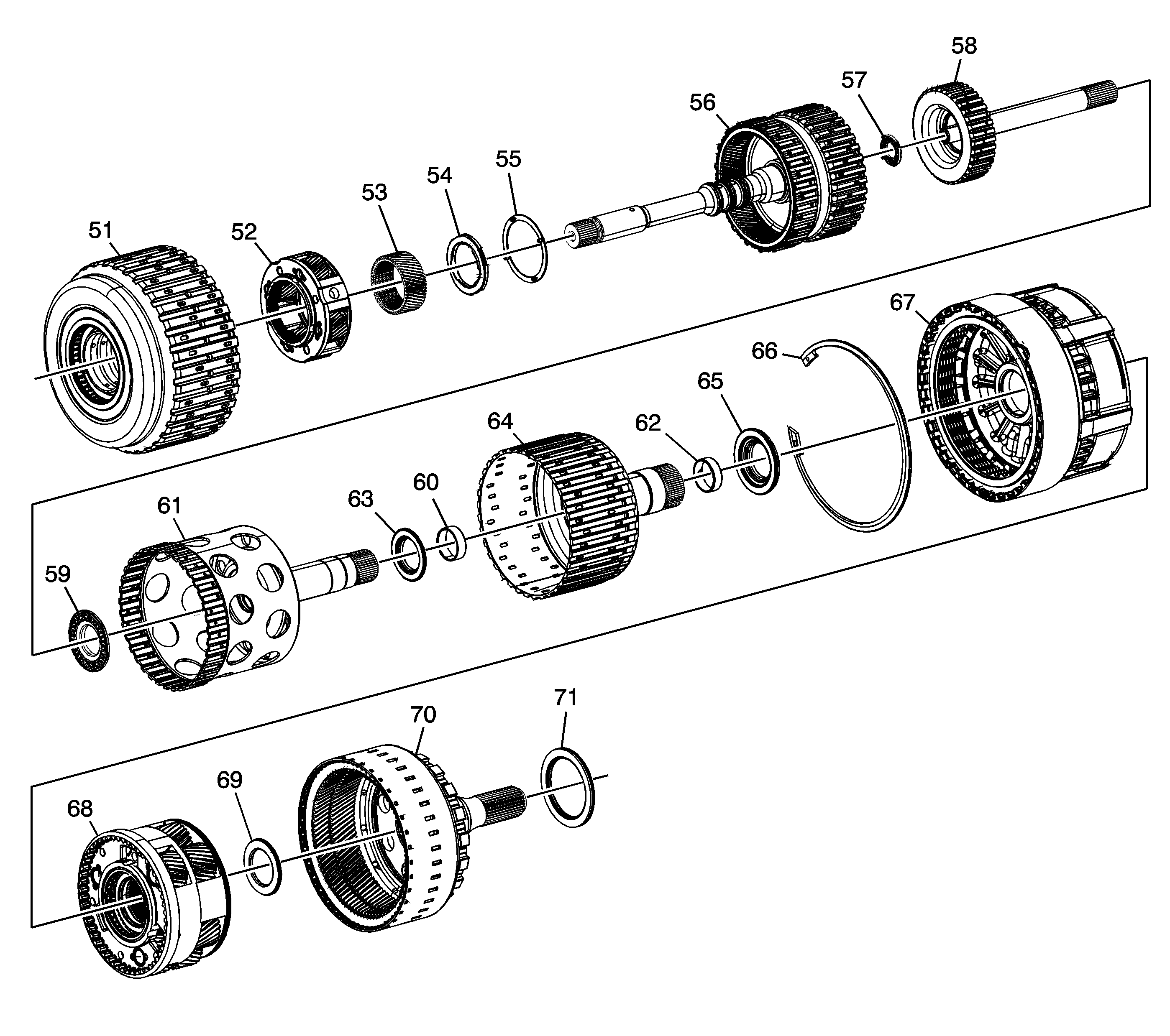
| Figure 2: |
Clutch Assemblies and Associated Parts
|
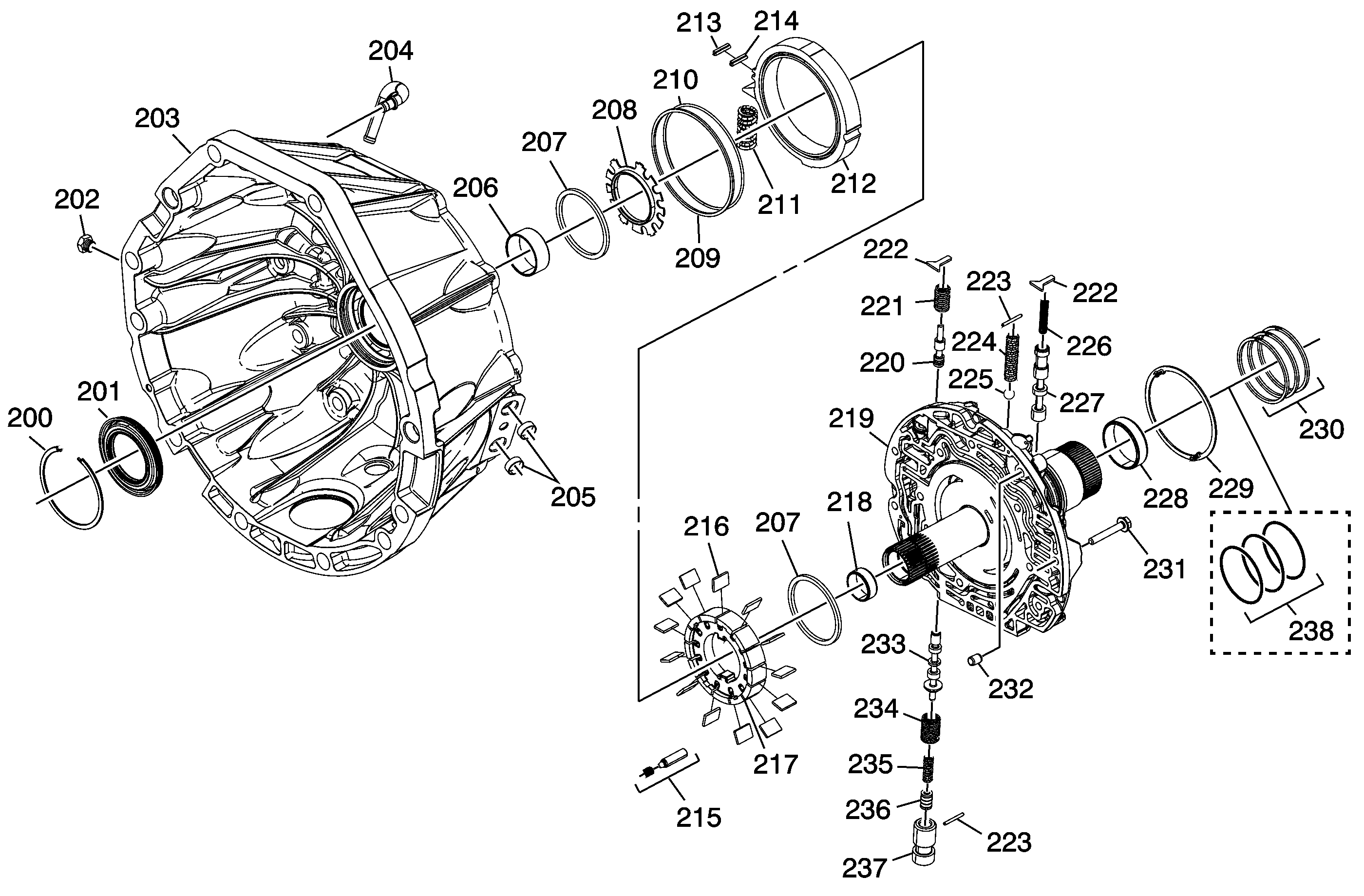
| Figure 3: |
Torque Converter (w/Fluid Pump) Housing Assembly
|
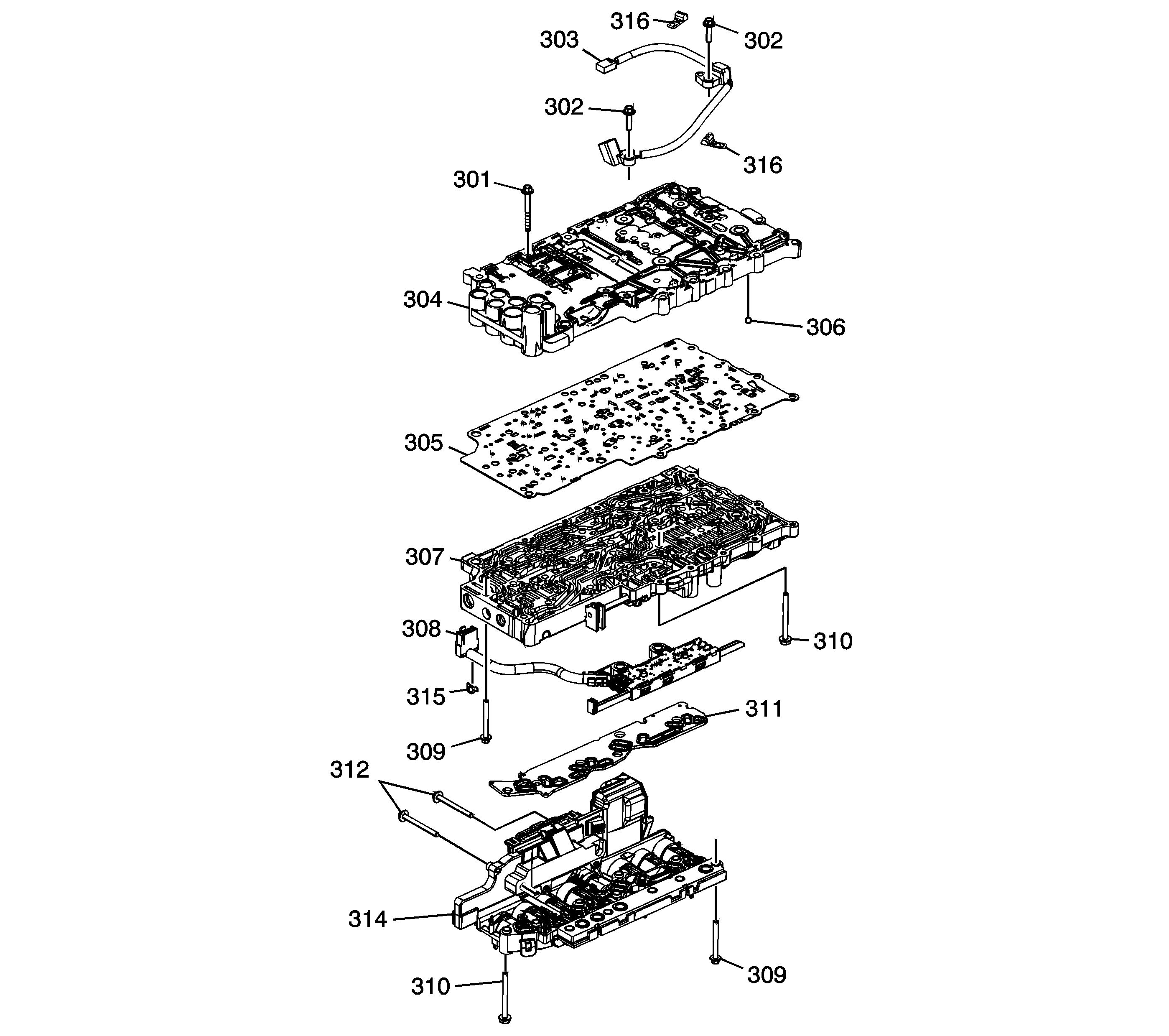
| Figure 4: |
Control (with Body and Valve) Valve Assembly
|
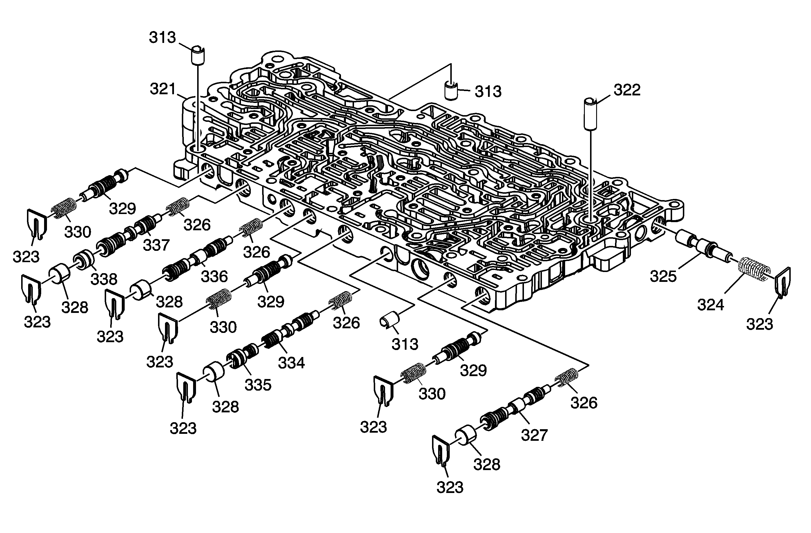
| Figure 5: |
Upper Control Valve Body Assembly
|
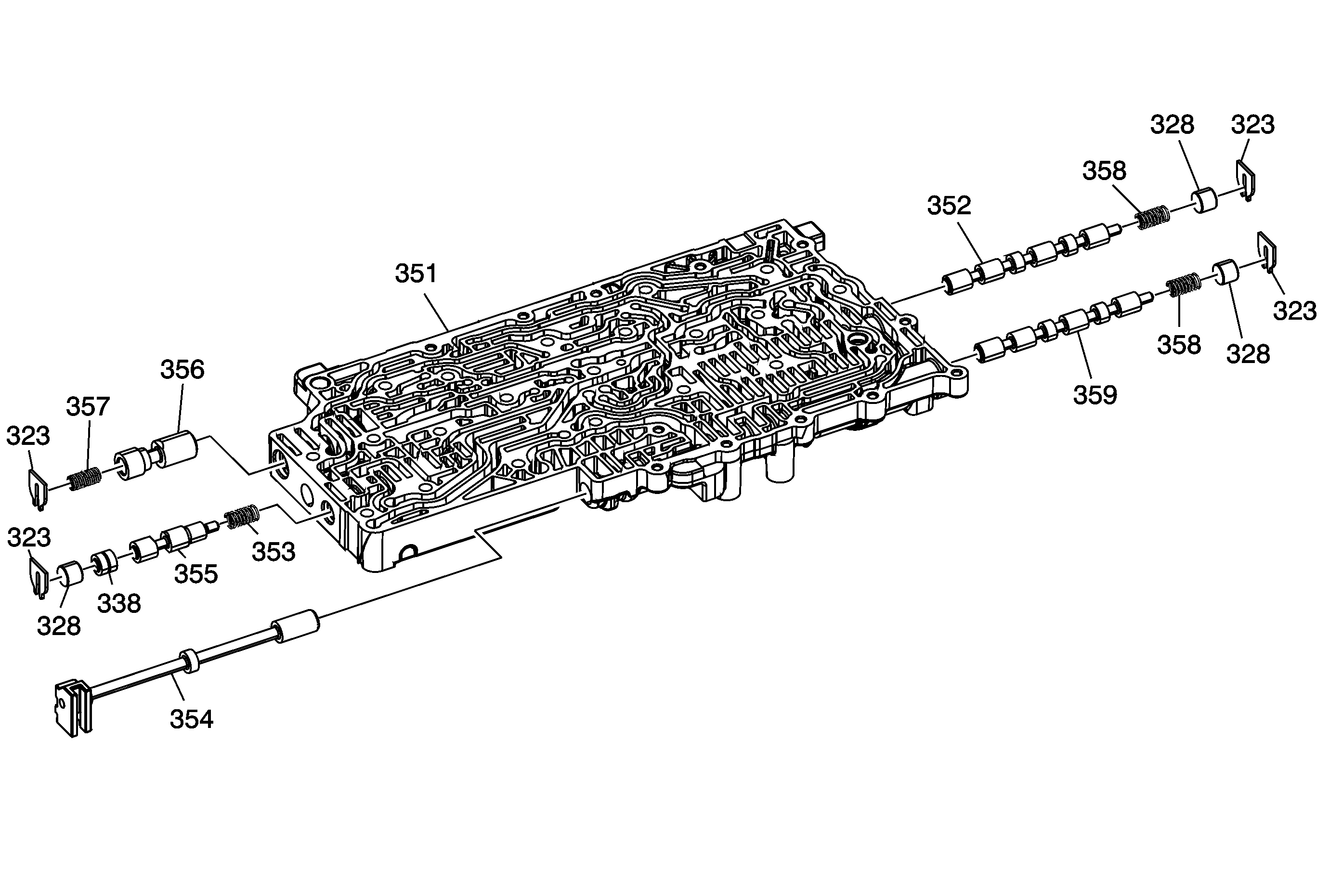
| Figure 6: |
Lower Control Valve Body Assembly
|
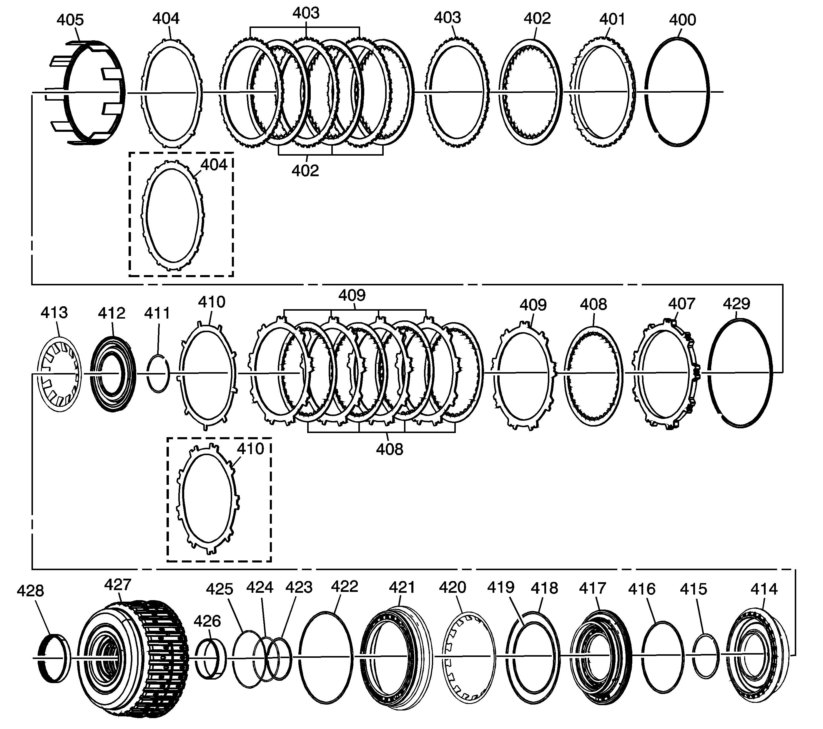
| Figure 7: |
1-2-3-4 and 3-5 Reverse
Clutch Assembly
|
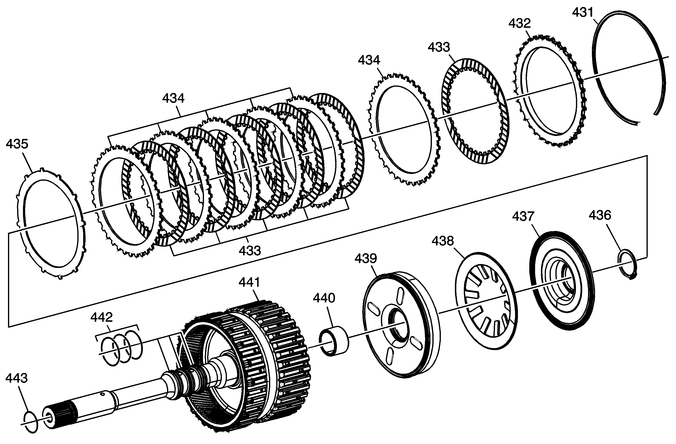
| Figure 8: |
4-5-6 (w/Turbine Shaft) Clutch Assembly
|
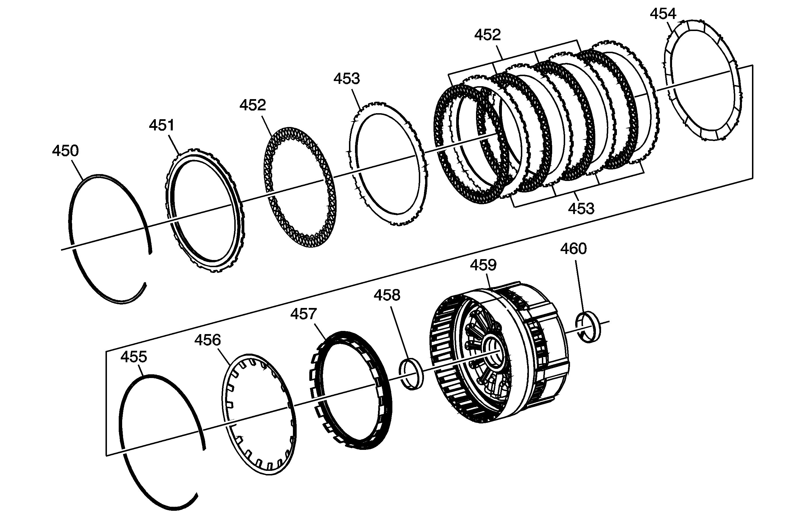
| Figure 9: |
2-6 Clutch Assembly
|
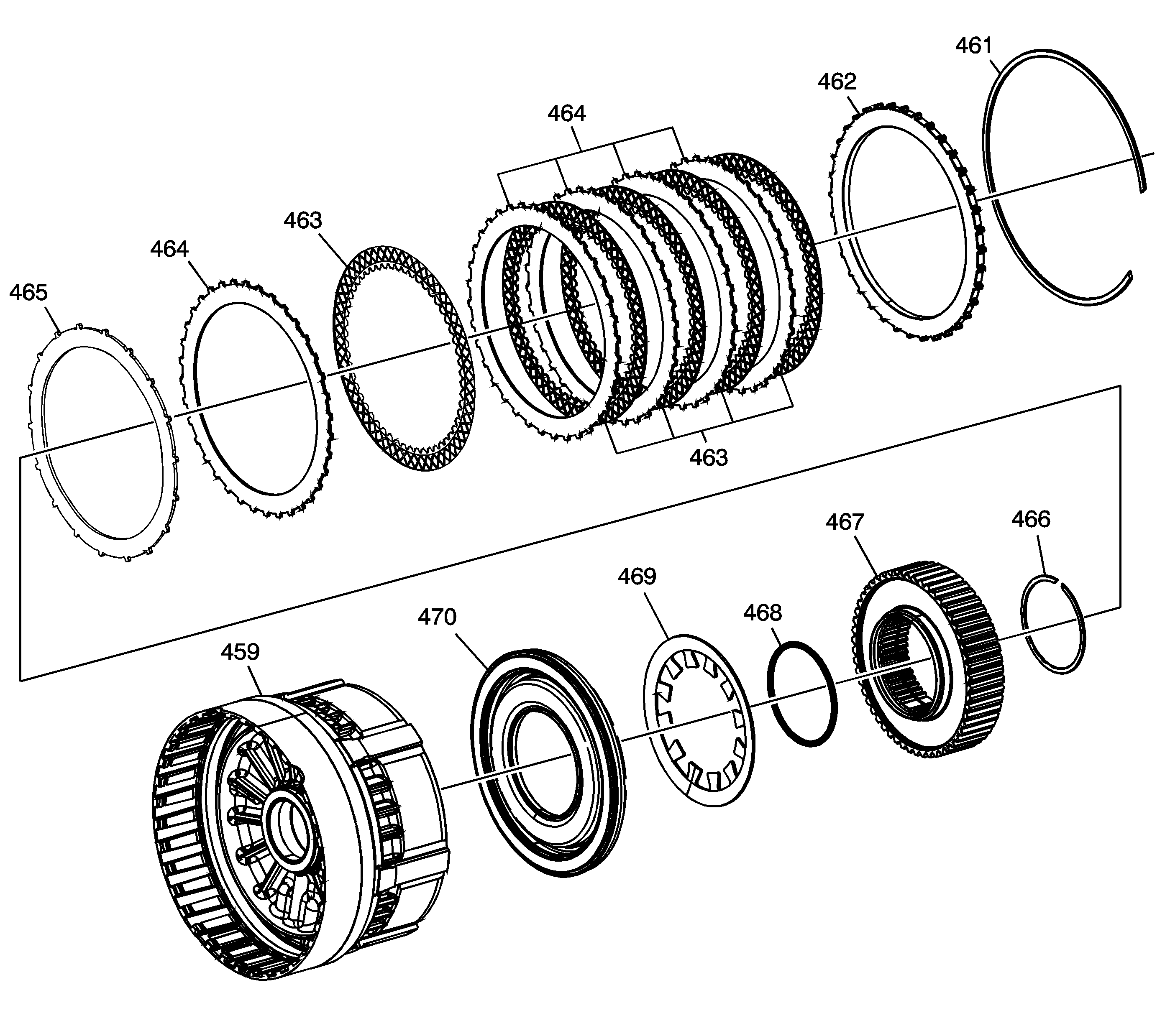
| Figure 10: |
Low and Reverse Clutch Assembly
|
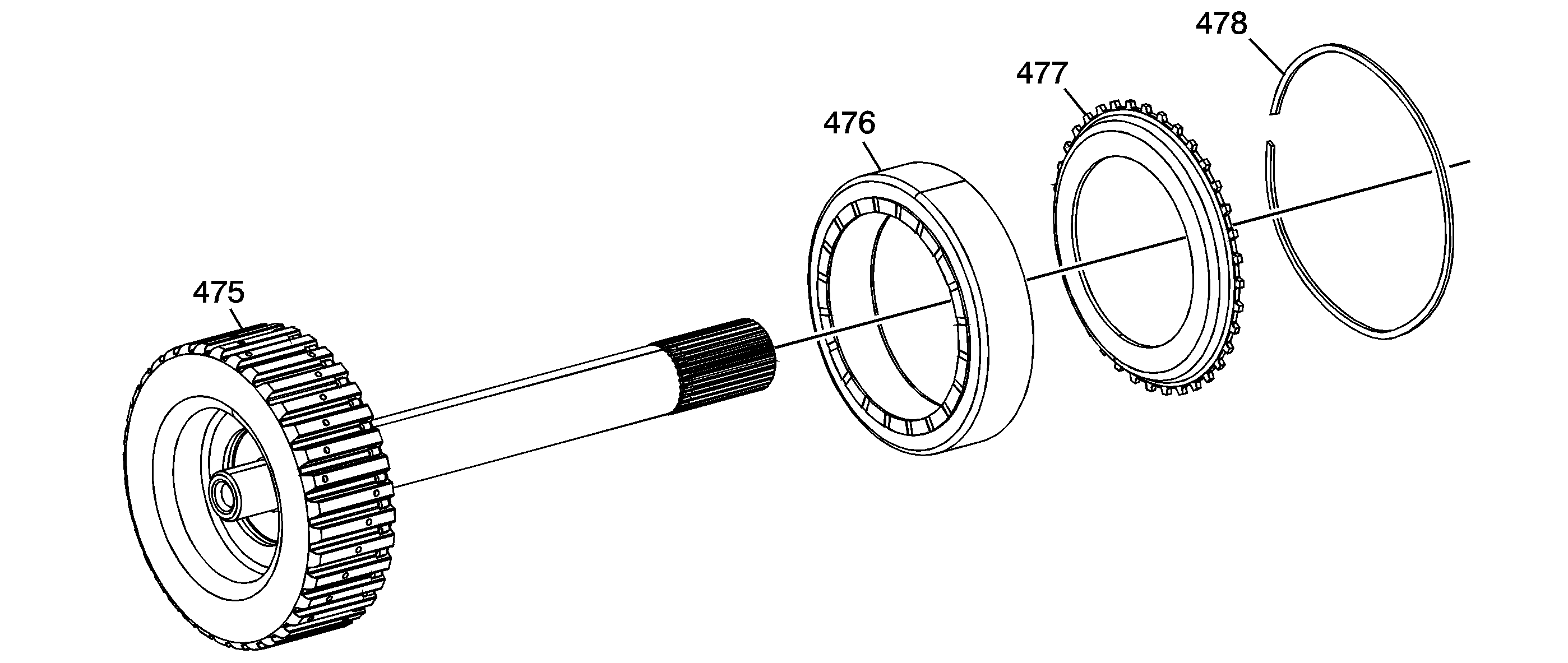
| Figure 11: |
4-5-6 Clutch Hub Assembly
|
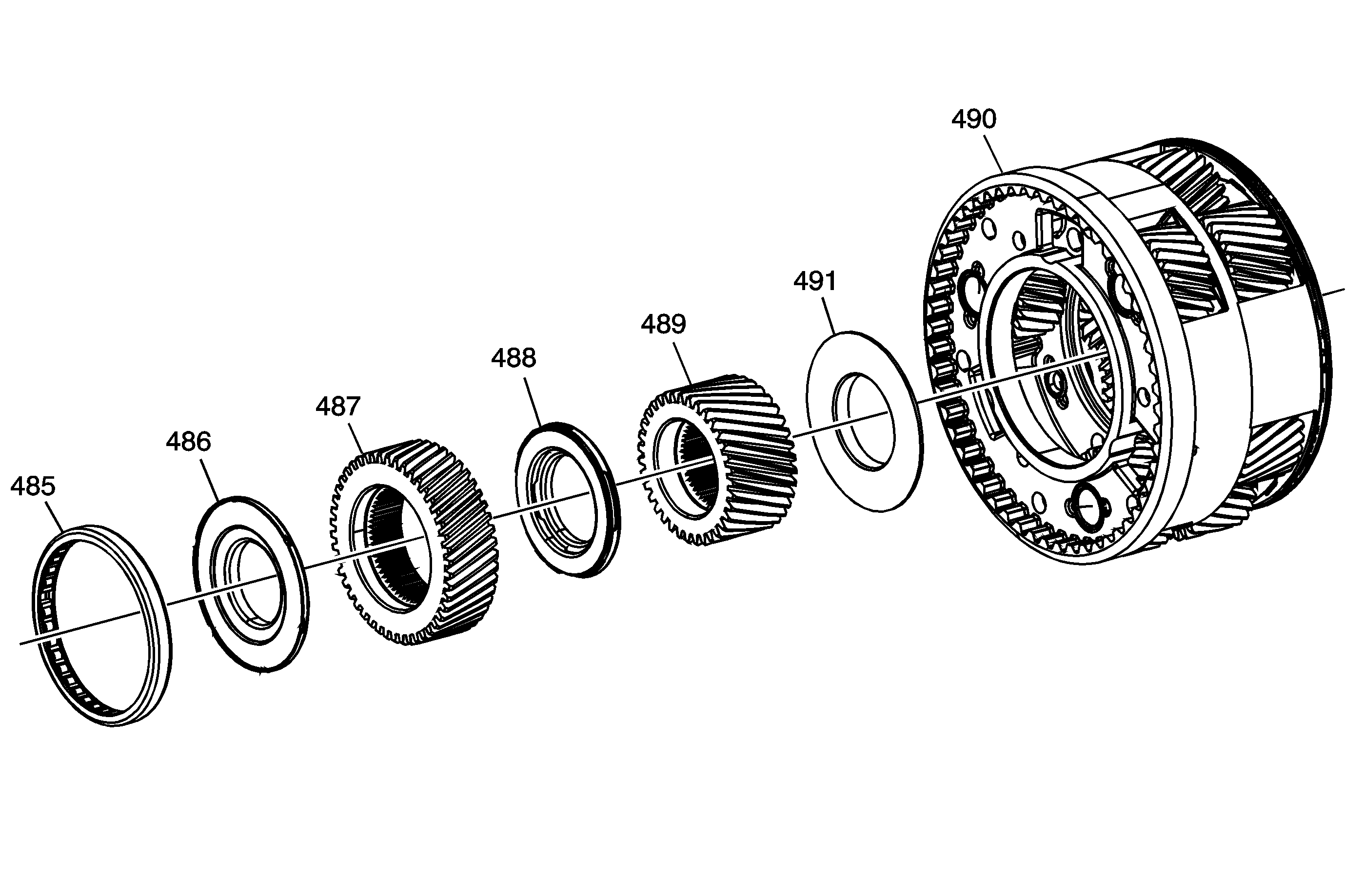
| Figure 12: |
Output Carrier Assembly
|
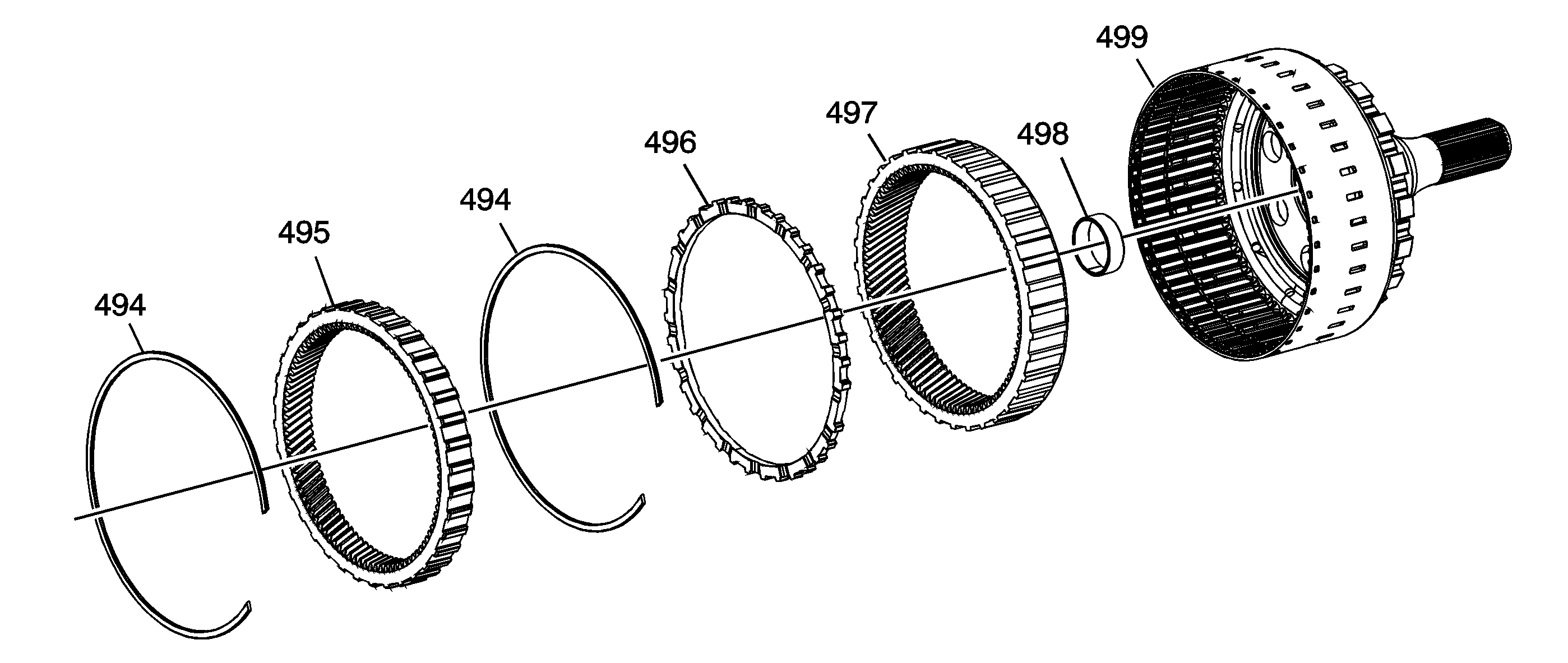
| Figure 13: |
Output Shaft Assembly
|
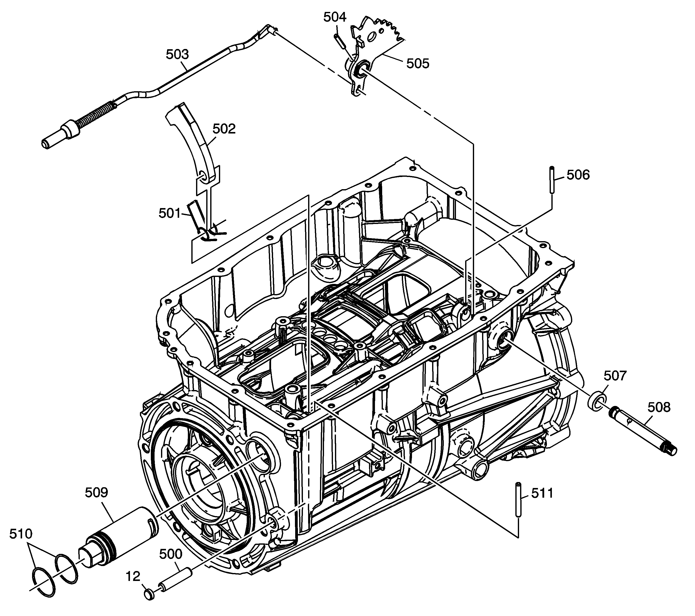
| Figure 14: |
Park System Components
|
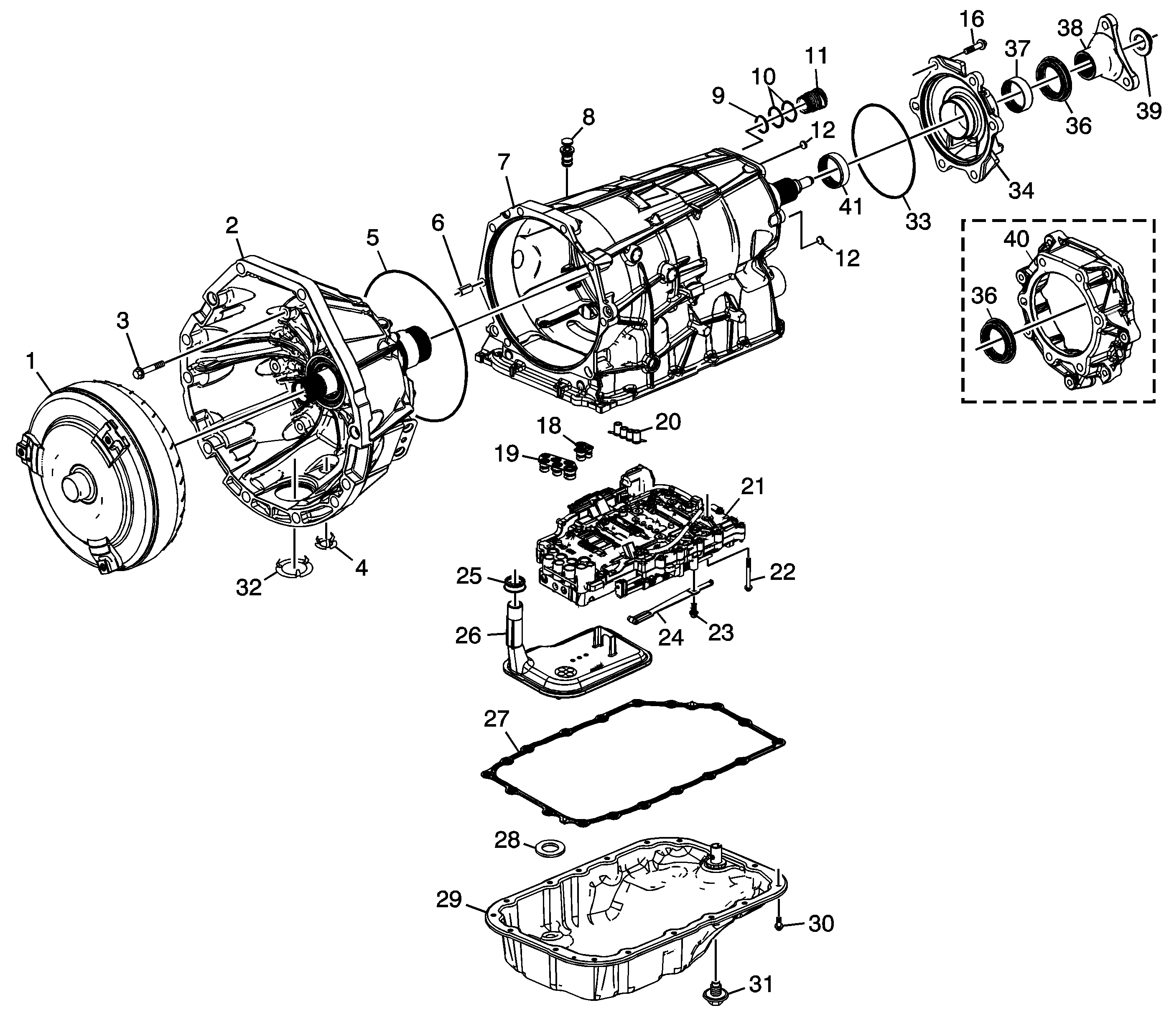
| Figure 1: |
Case and Associated Parts
|
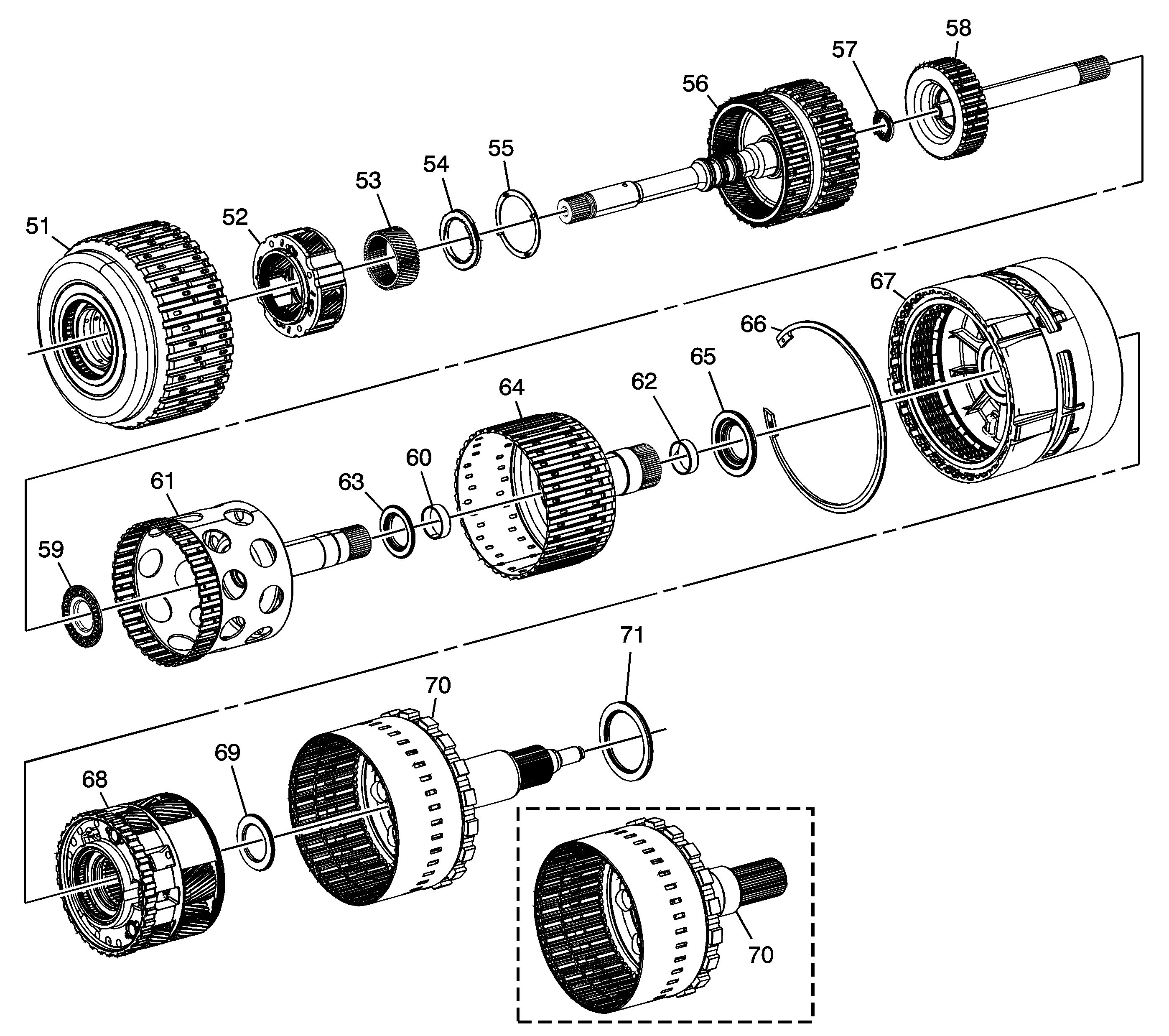
| Figure 2: |
Clutch Assemblies and Associated Parts
|
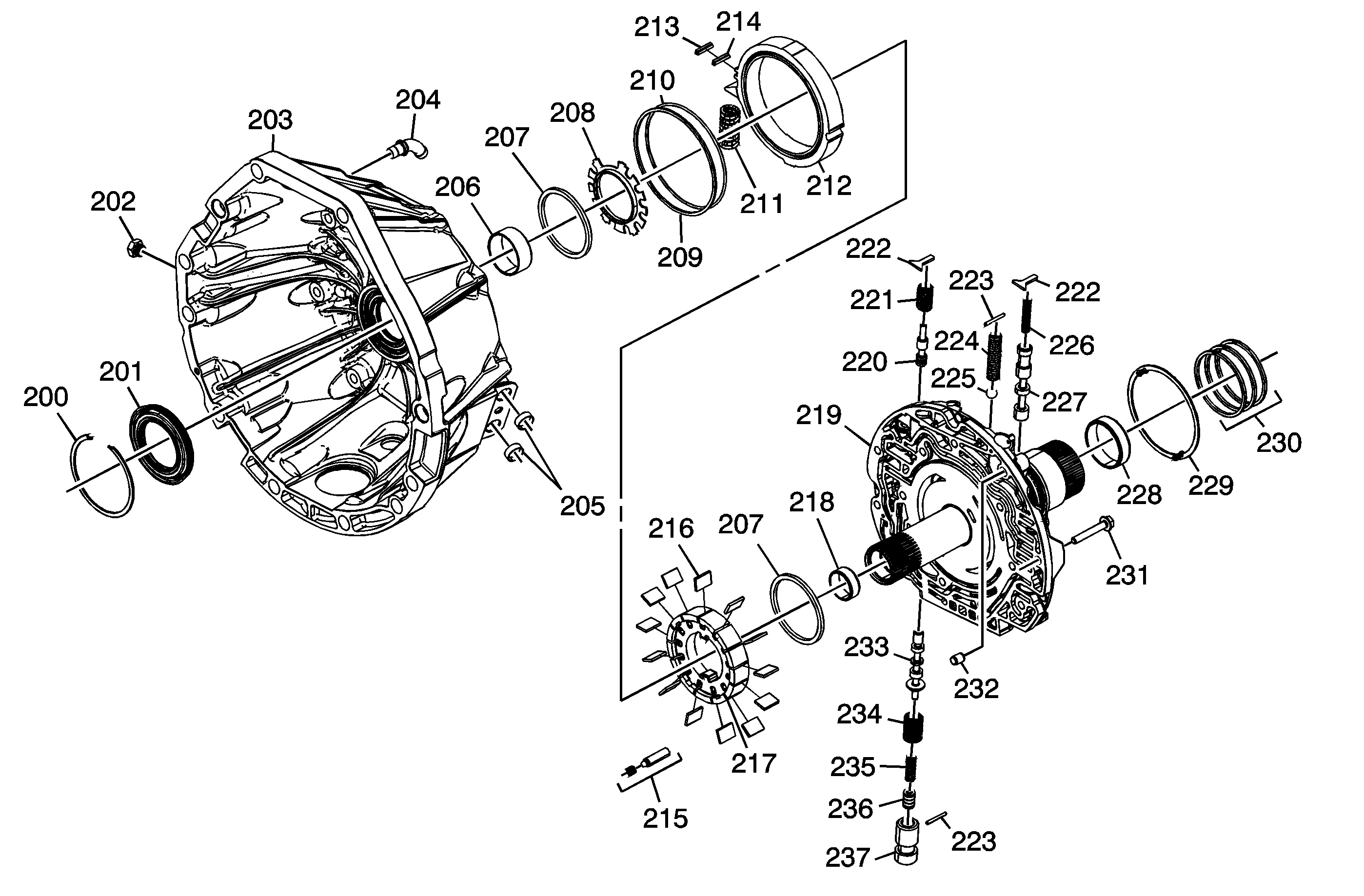
| Figure 3: |
Torque Converter (w/Fluid Pump) Housing Assembly
|
| Figure 4: |
Control (with Body and Valve) Valve Assembly

|
| Figure 5: |
Upper Control Valve Body Assembly

|
| Figure 6: |
Lower Control Valve Body Assembly

|
| Figure 7: |
1-2-3-4 and 3-5 Reverse
Clutch Assembly

|
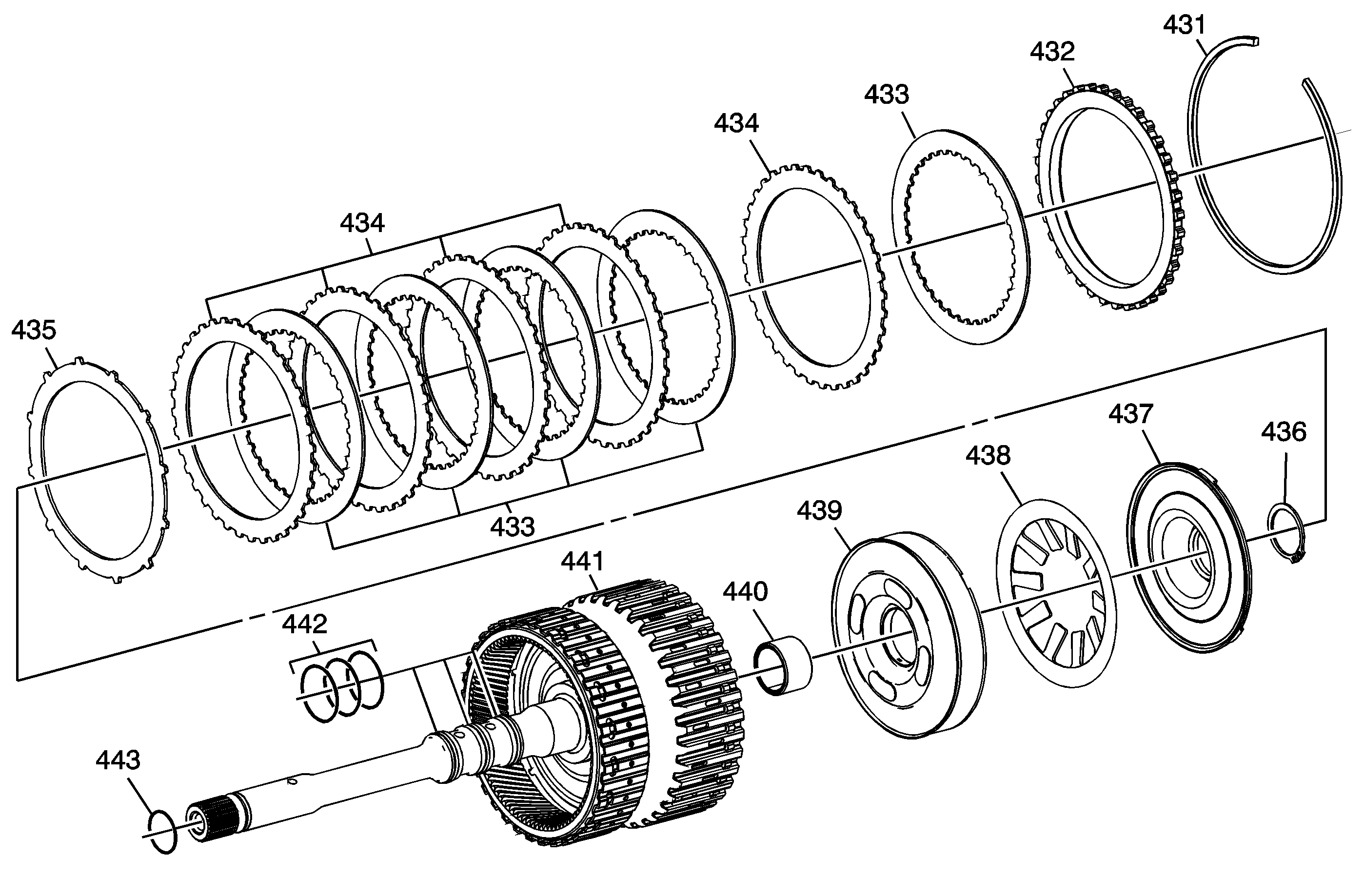
| Figure 8: |
4-5-6 (w/Turbine Shaft) Clutch Assembly
|
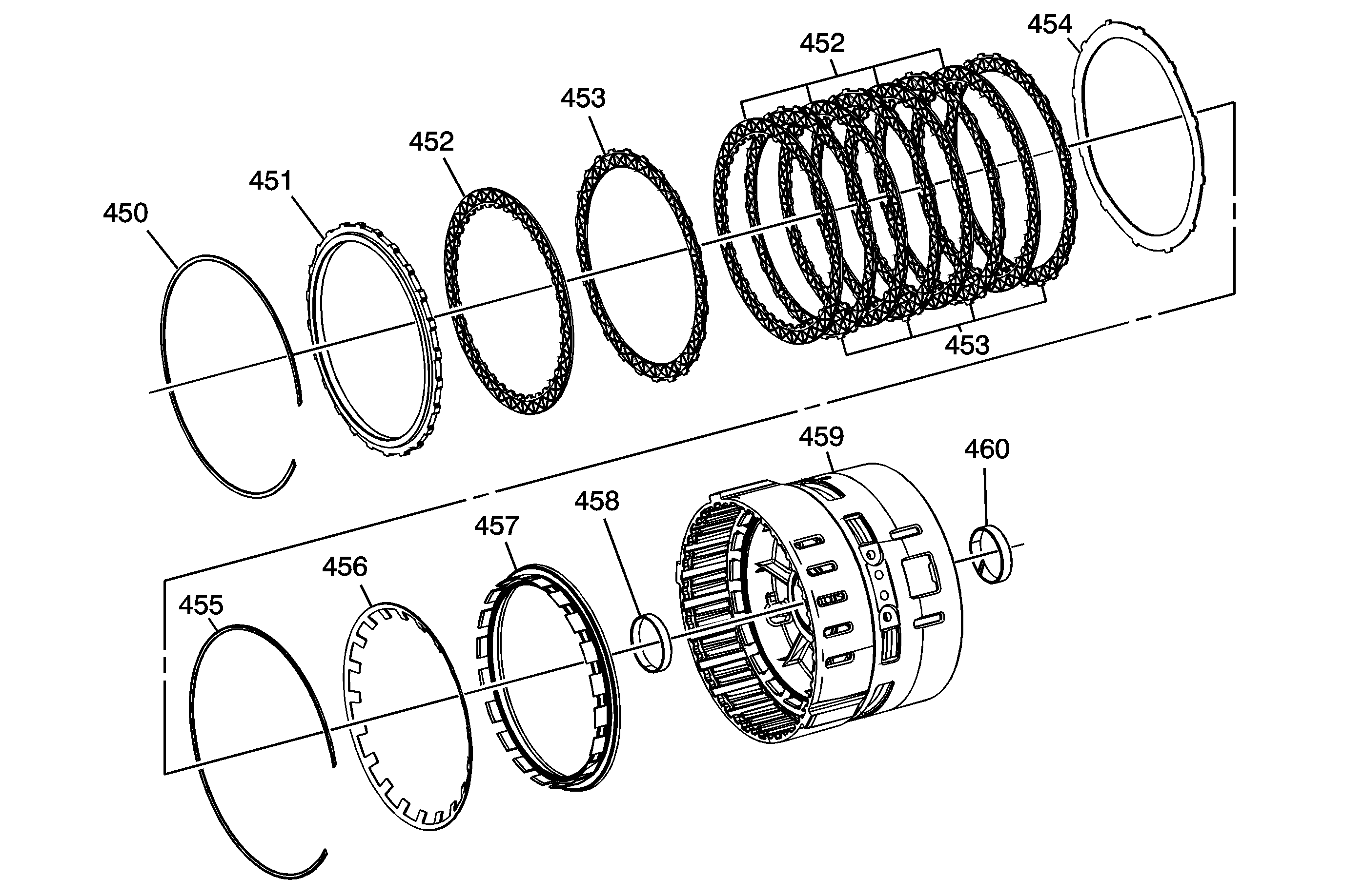
| Figure 9: |
2-6 Clutch Assembly
|
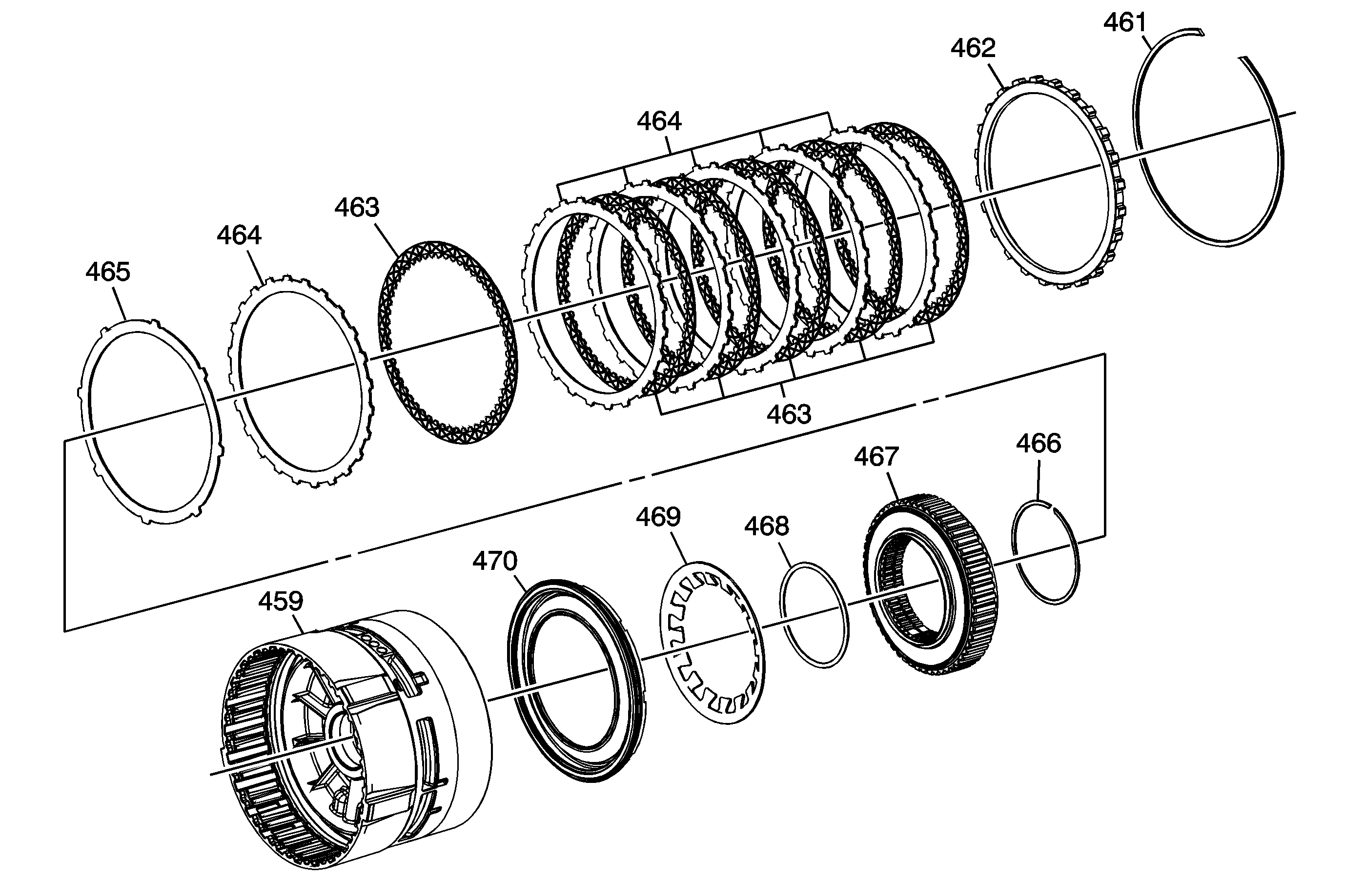
| Figure 10: |
Low and Reverse Clutch Assembly
|
| Figure 11: |
4-5-6 Clutch Hub Assembly

|
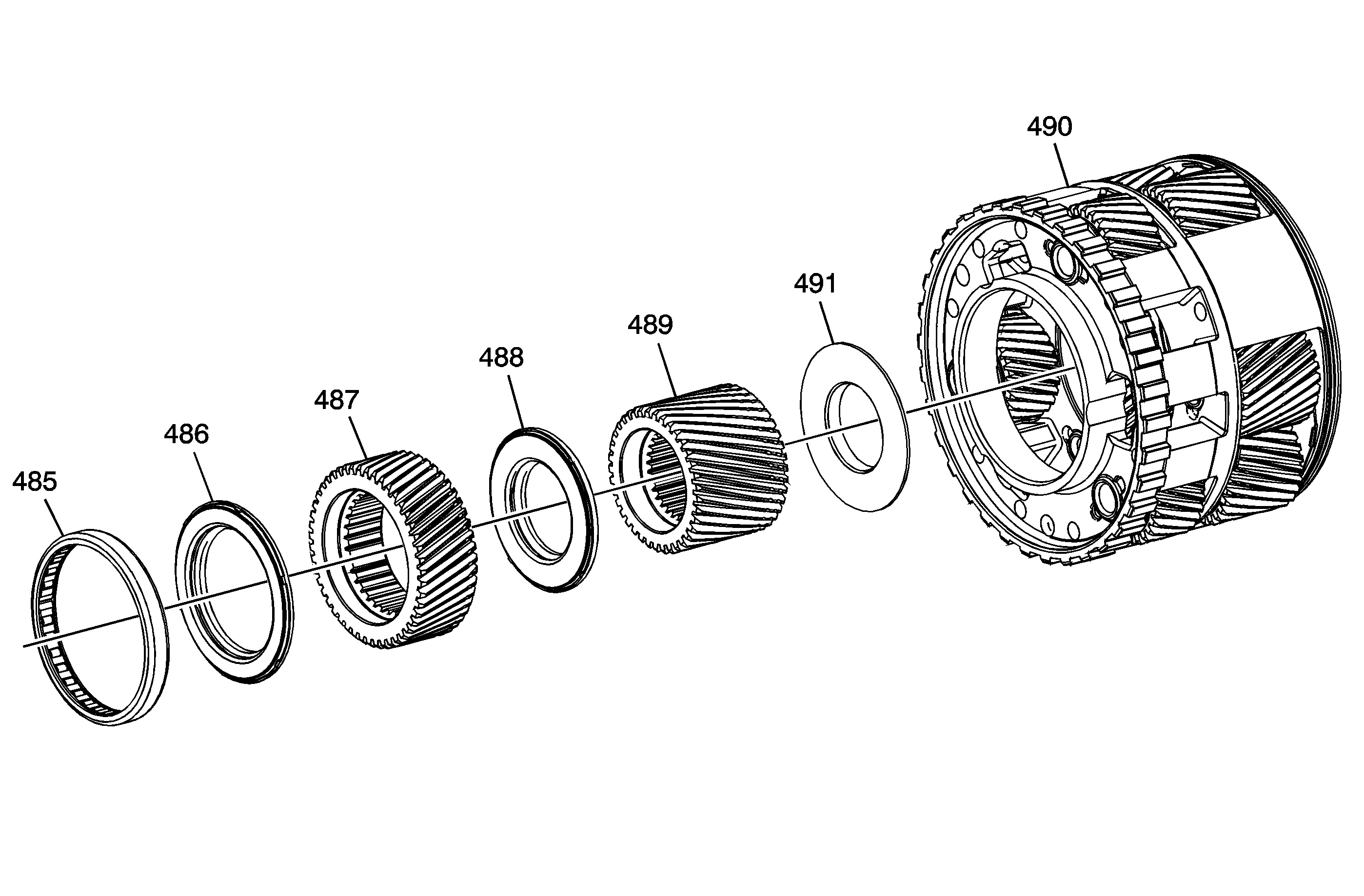
| Figure 12: |
Output Carrier Assembly
|
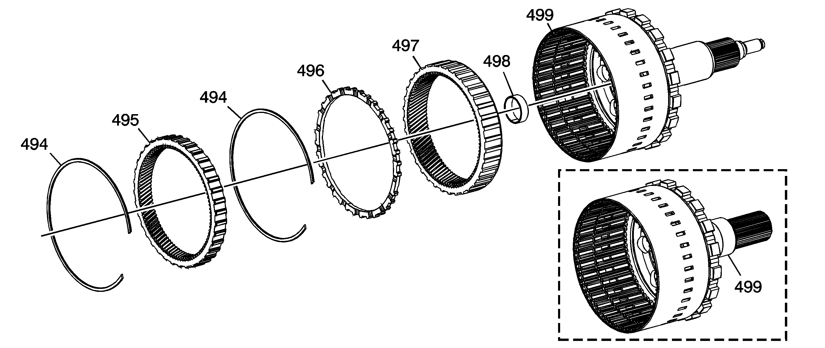
| Figure 13: |
Output Shaft Assembly
|
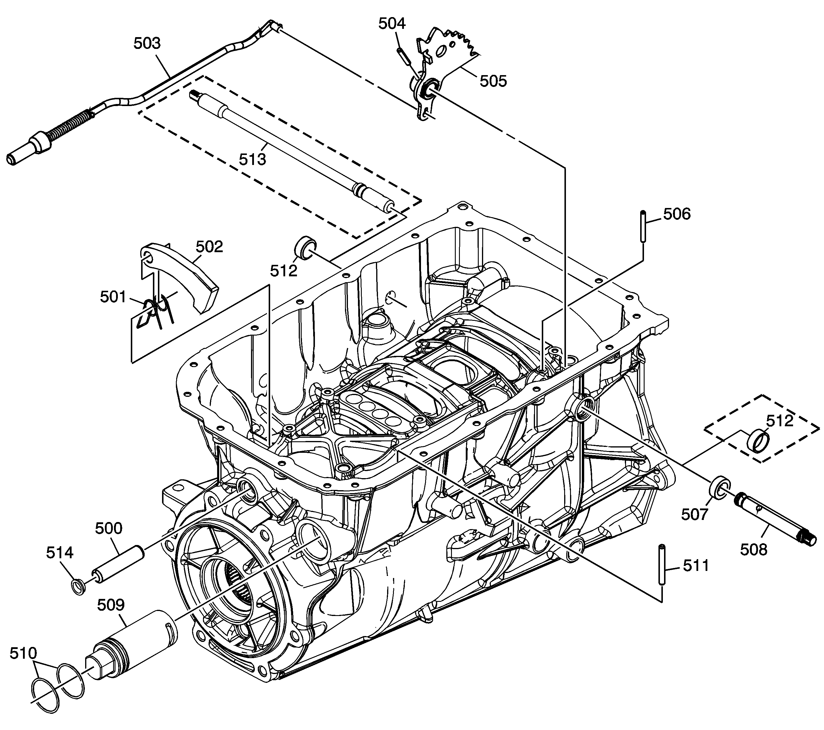
| Figure 14: |
Park System Components
|


