For 1990-2009 cars only
Steering Wheel Position Sensor Replacement with JL7
Special Tools
J 42640 Steering Column Anti-Rotation Pin
Removal Procedure
- Disable the supplemental inflatable restraint (SIR) system. Refer to SIR Disabling and Enabling.
- Turn the steering wheel so that the front wheels are pointing straight ahead.
- Insert anti-rotation pin J 42640 into the steering column access hole in order to lock the steering column.
- Remove the driver knee bolster bracket. Refer to Driver Knee Bolster Bracket Replacement.
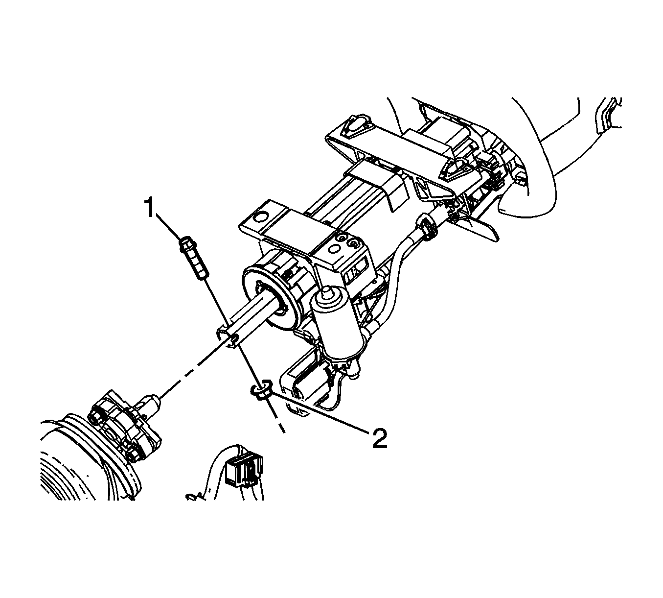
- Remove the upper intermediate steering shaft bolt (1) and nut (2).
- Separate the upper intermediate steering shaft from the steering column.
- Disconnect the steering wheel position sensor electrical connector.
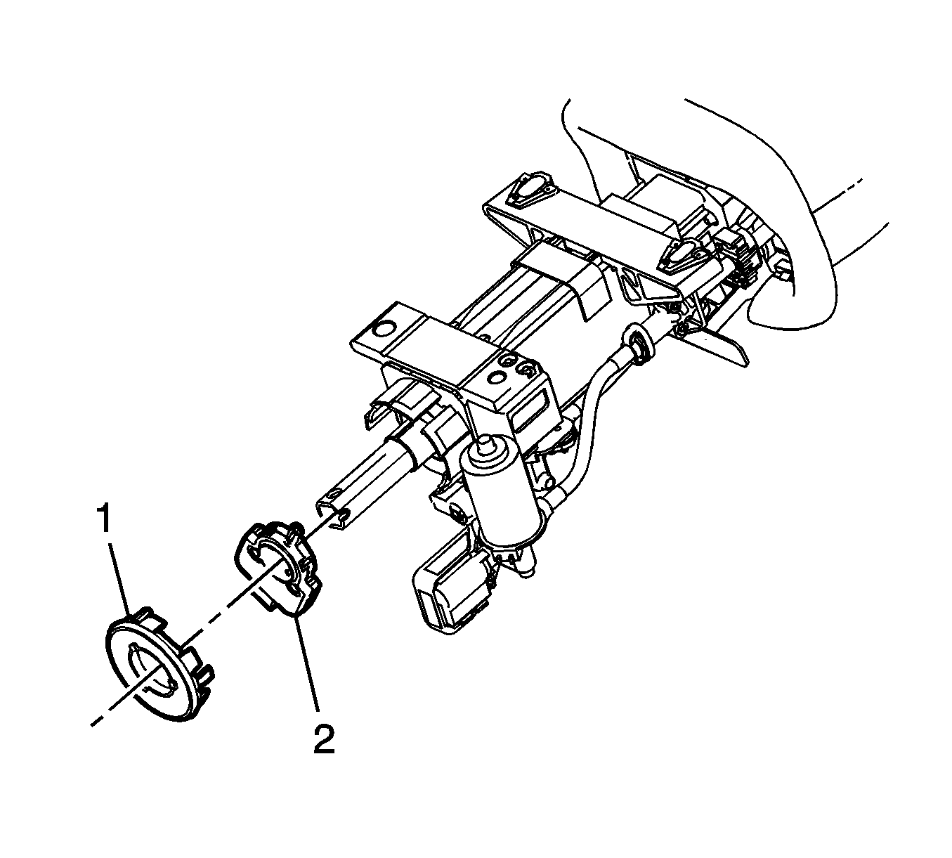
- Remove the steering shaft lower bearing seal retainer (1).
- Unclip the steering wheel position sensor (2) and slide it off of the steering shaft.
Notice: The front wheels of the vehicle must be maintained in the straight ahead position and the steering column must be in the LOCK position before disconnecting the steering column or intermediate shaft. Failure to follow these procedures will cause improper alignment of some components during installation and result in damage to the SIR coil assembly.


Installation Procedure
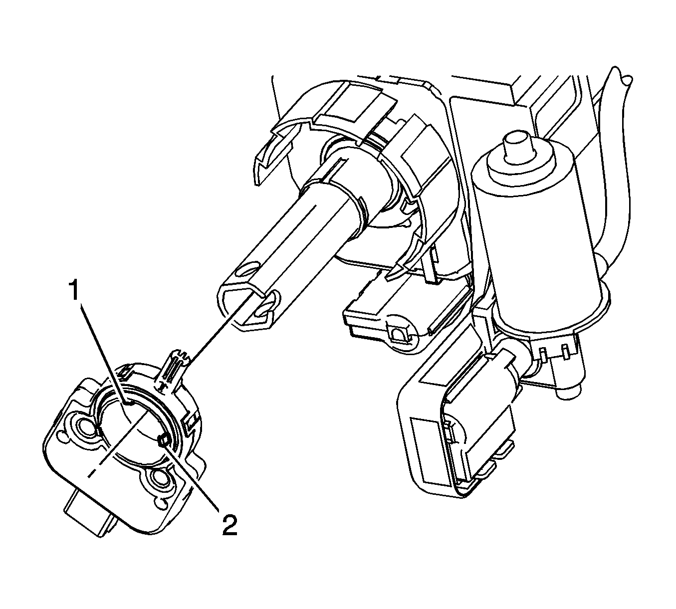
- Use the alignment shaft (1) on the steering wheel position sensor to guide it into place on the steering shaft.
- Slide the steering wheel position sensor onto the steering shaft until the lock tabs (2) are secured.
- Install the steering shaft lower bearing seal retainer (1).
- Connect the upper intermediate steering shaft (3) to the steering column.
- Install the upper intermediate steering shaft bolt (1) and nut (2)
- Connect the steering wheel position sensor electrical connector.
- Install the driver knee bolster bracket. Refer to Driver Knee Bolster Bracket Replacement.
- Remove anti-rotation pin J 42640 .
- Enable the supplemental inflatable restraint (SIR) system. Refer to SIR Disabling and Enabling.

Important: After installation, ensure that nothing contacts the side of the steering wheel position sensor.


Notice: Refer to Fastener Notice in the Preface section.
Tighten
Tighten the nut to 47 N·m (35 lb ft).
