For 1990-2009 cars only
Removal Procedure
Caution: Refer to Oxygen Sensor Caution in the Preface section.
Note:
• Bank 1 on the LC3 engine is the right side of the engine while sitting in the driver seat. • Sensor 1 is the sensor closest to the engine, or farthest forward towards the front of vehicle. • A special anti-seize compound is used on the oxygen sensor threads. New service sensors should already have the compound applied to the threads. Coat the threads of a reused sensor with anti-seize compound P/N 5613695 or equivalent.
- Remove the engine sight shield. Refer to Intake Manifold Sight Shield Replacement.
- Remove the front air inlet housing panel. Refer to Air Inlet Housing Front Panel Replacement.
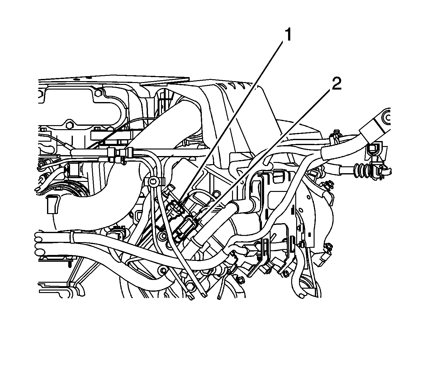
- Disconnect the oxygen sensor electrical connector (1) from the engine wiring harness connector at the rear of the right head.
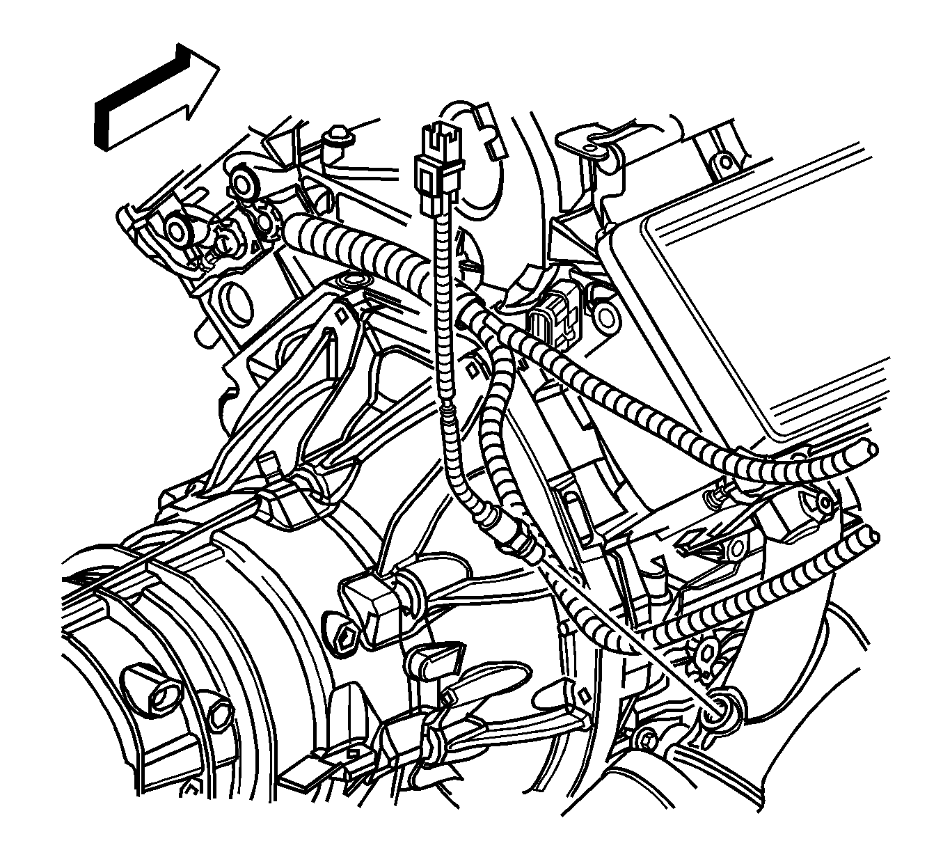
- Remove the wire harness from the bracket.
- Note the wire routing and attachment points for reassembly.
- Raise and support the vehicle. Refer to Lifting and Jacking the Vehicle.
- Remove oxygen sensor from the exhaust manifold.


Installation Procedure
- Install the heated oxygen sensor (HO2S) in the exhaust manifold and tighten to 42 N·m (31 lb ft).
- Lower the vehicle.
- Route and attach the wiring as noted during disassembly.
- Connect the oxygen sensor electrical connector (1) to the engine wiring harness connector at the rear of the right head.
- Install the wire harness to the bracket.
- Install the front air inlet housing panel. Refer to Air Inlet Housing Front Panel Replacement.
- Install the engine sight shield. Refer to Intake Manifold Sight Shield Replacement.
Caution: Refer to Fastener Caution in the Preface section.


