4-5-6 Clutch Overhaul 6L80
| Table 1: | 4-5-6 Clutch Plates Removal |
| Table 2: | 4-5-6 Clutch Piston Removal |
| Table 3: | Turbine Shaft Fluid Seal Ring Replacement |
| Table 4: | 4-5-6 Clutch Piston Installation |
| Table 5: | 4-5-6 Clutch Plates Installation |
4-5-6 Clutch Plates Removal
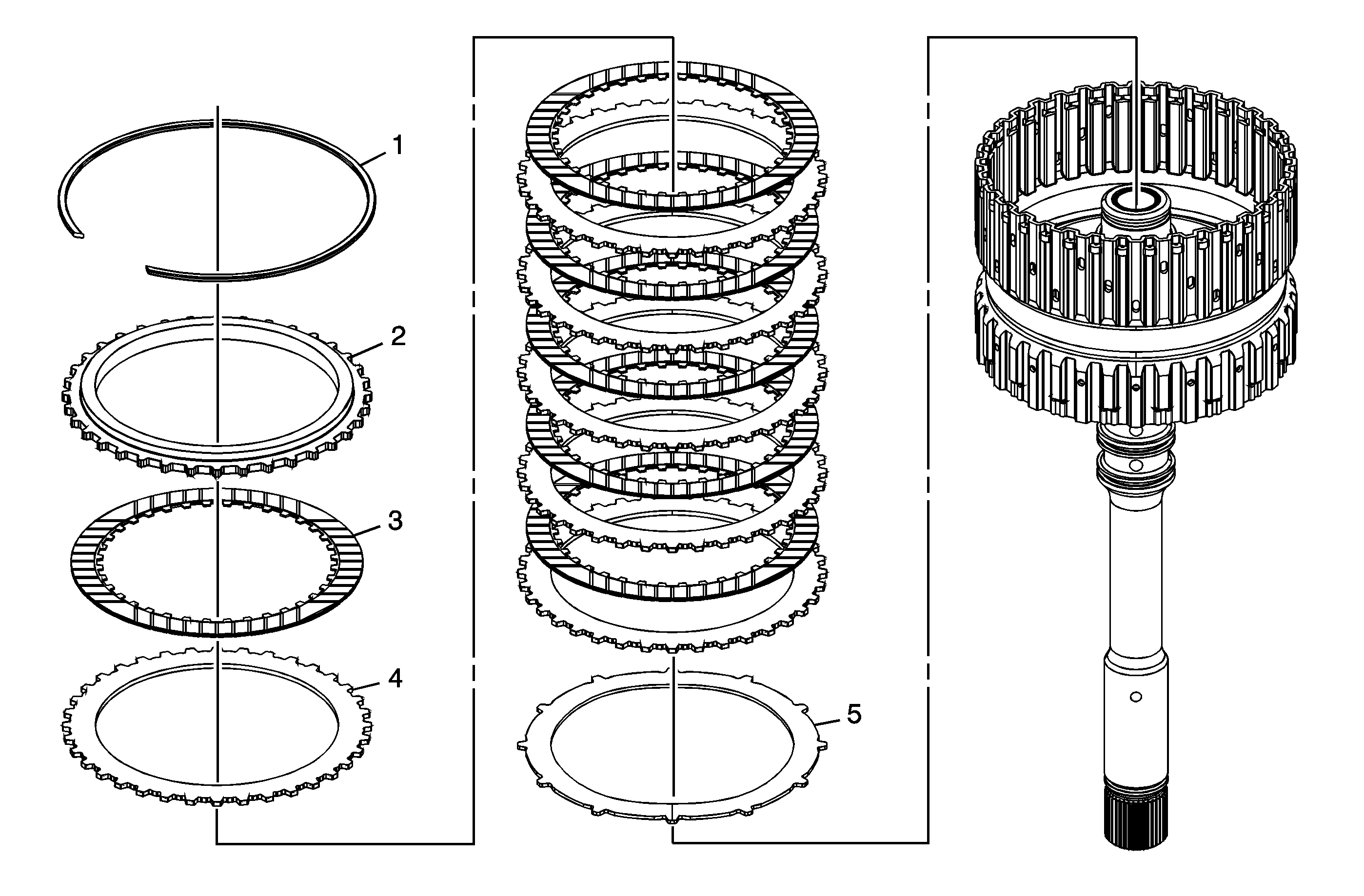
Callout | Component Name |
|---|---|
1 | 4-5-6 Clutch Backing Plate Retaining Ring |
2 | 4-5-6 Clutch Backing Plate |
3 | 4-5-6 Clutch Plate Assembly (Qty: 6) |
4 | 4-5-6 Clutch Plate (Qty: 6) |
5 | 4-5-6 Clutch (Waved) Plate |
4-5-6 Clutch Piston Removal
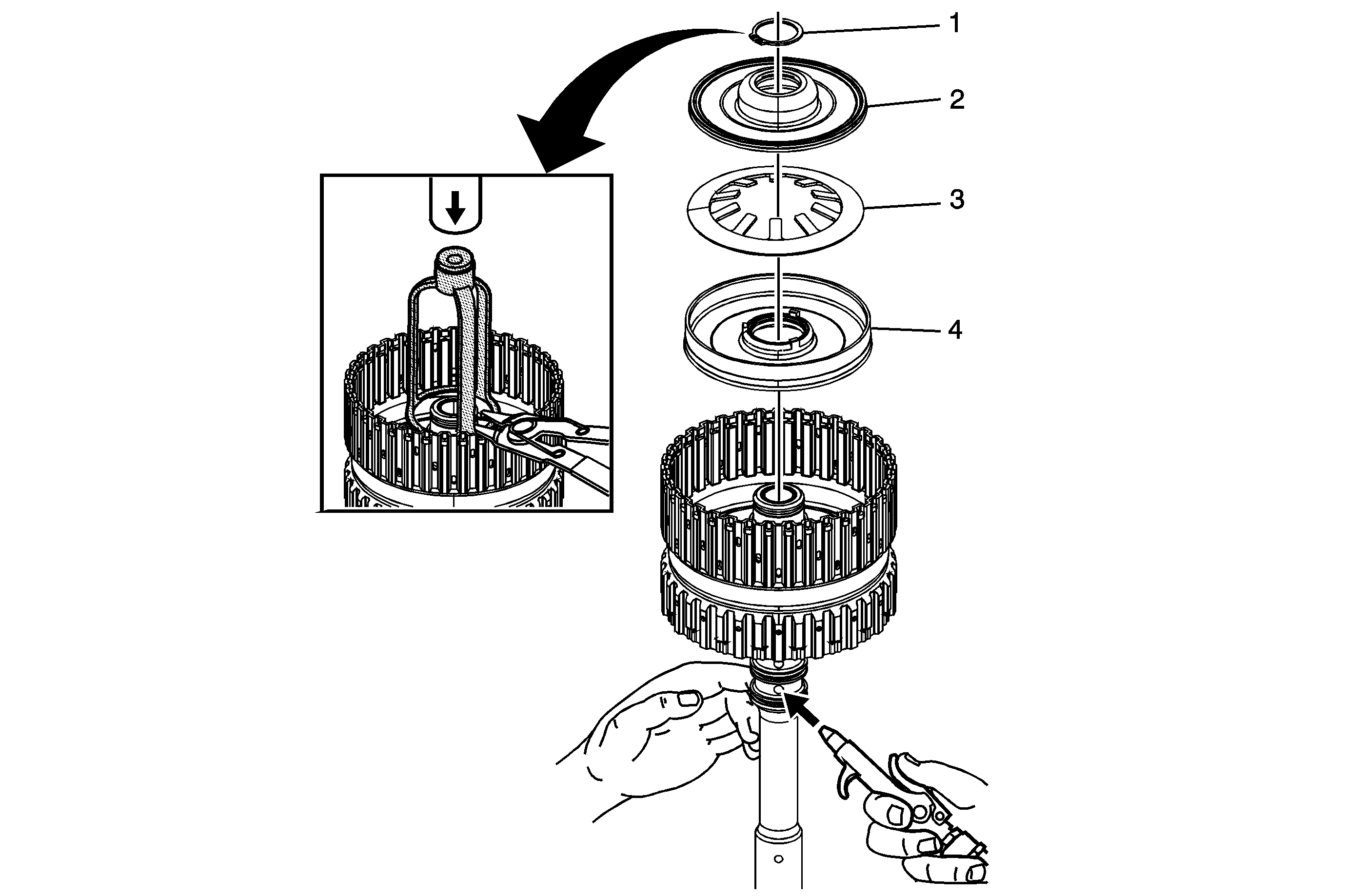
Callout | Component Name |
|---|---|
1 | 4-5-6 Clutch Piston Dam Retaining Ring Caution: Use care when compressing the 4-5-6 clutch piston assembly, spring and dam assembly. Compressing the dam assembly too much may damage it. Caution: Refer to Retaining Ring Reuse Caution in the Preface section. Special ToolJ 43074 Clutch Spring Compressor |
2 | 4-5-6 Clutch Piston Dam Assembly Tip |
3 | 4-5-6 Clutch Spring |
4 | 4-5-6 Clutch Piston Assembly Tip |
Turbine Shaft Fluid Seal Ring Replacement
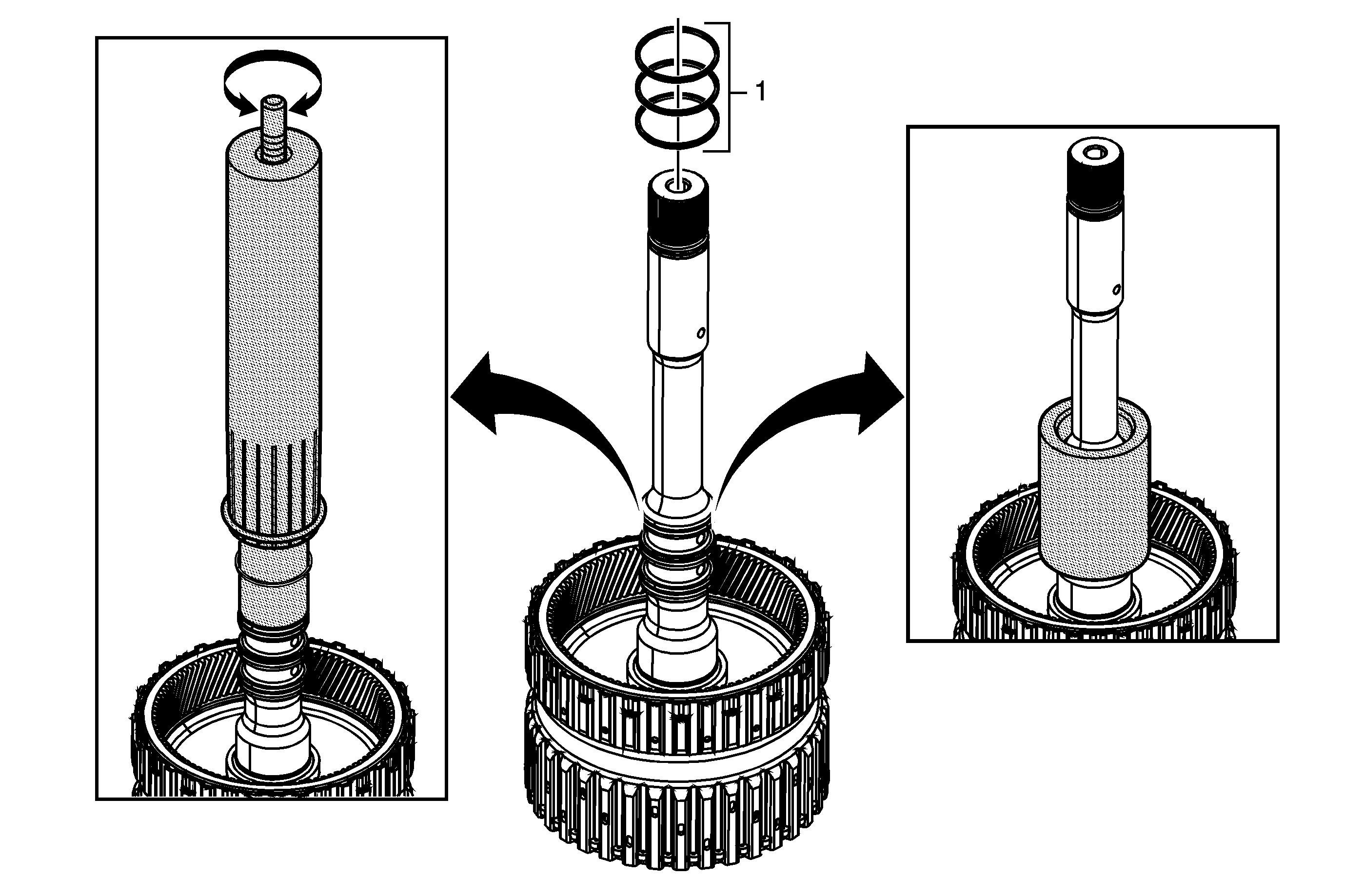
Callout | Component Name | ||||||
|---|---|---|---|---|---|---|---|
Preliminary Procedures
| |||||||
1 | Turbine Shaft Fluid Seal Ring (Qty: 3) Caution: Do not use old seal rings. Install NEW seal rings. Reusing old seal rings may cause internal transmission leaks and transmission damage. Caution: Size the fluid seal rings for at least 5 minutes after installation to obtain proper seal ring size. Failure to do so may cause internal transmission leaks and transmission damage. Tip Special Tools
| ||||||
4-5-6 Clutch Piston Installation
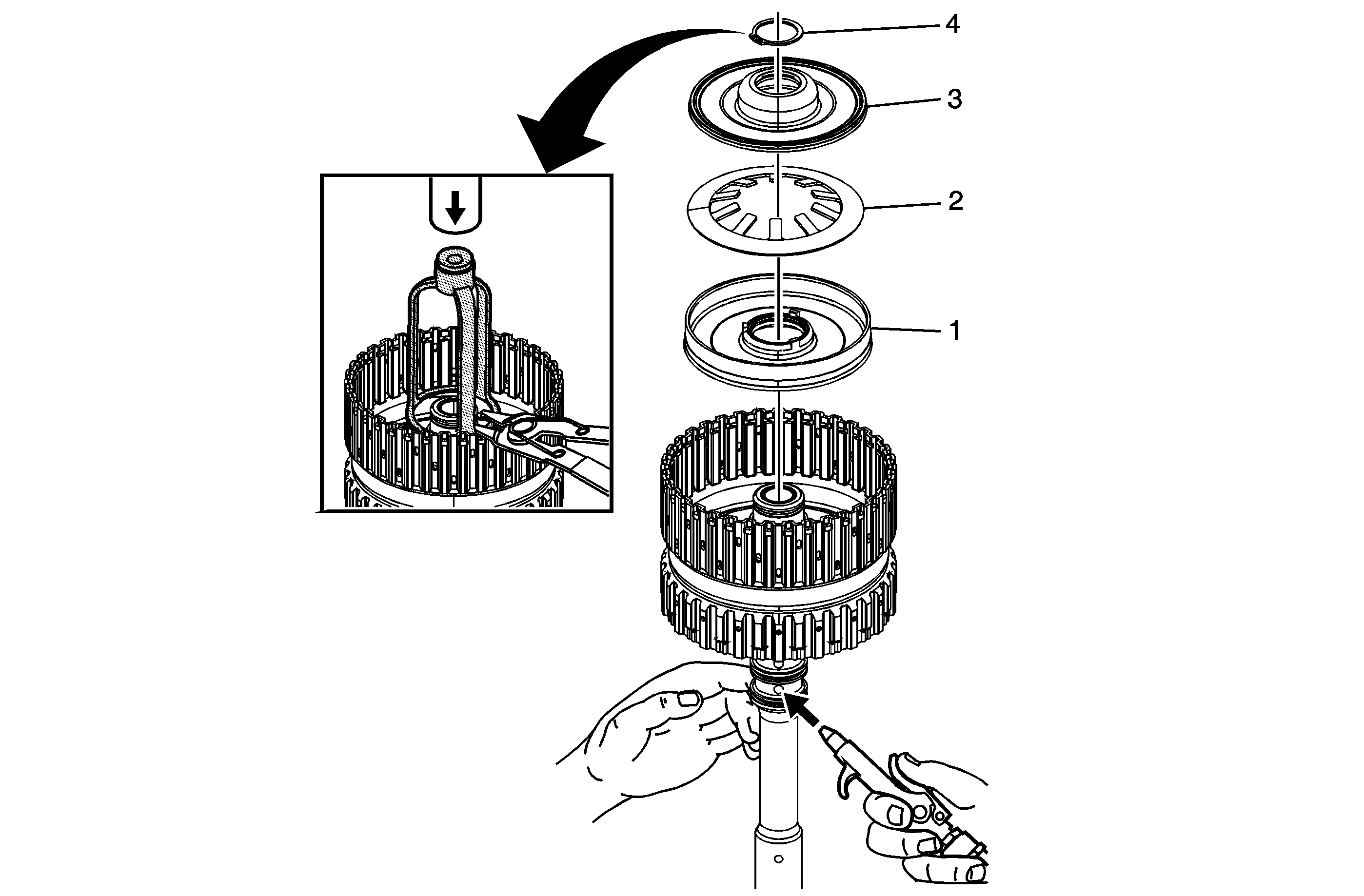
Callout | Component Name |
|---|---|
1 | 4-5-6 Clutch Piston Assembly |
2 | 4-5-6 Clutch Spring Caution: Ensure the spring tabs are facing up during installation. Failure to do so may cause damage to the clutch assembly. |
3 | 4-5-6 Clutch Piston Dam Assembly Tip |
4 | 4-5-6 Clutch Piston Dam Retaining Ring Caution: Use care when compressing the 4-5-6 clutch piston assembly, spring and dam assembly. Compressing the dam assembly too much may damage it. Caution: Refer to Retaining Ring Reuse Caution in the Preface section. Tip Special ToolJ 43074 Clutch Spring Compressor |
4-5-6 Clutch Plates Installation
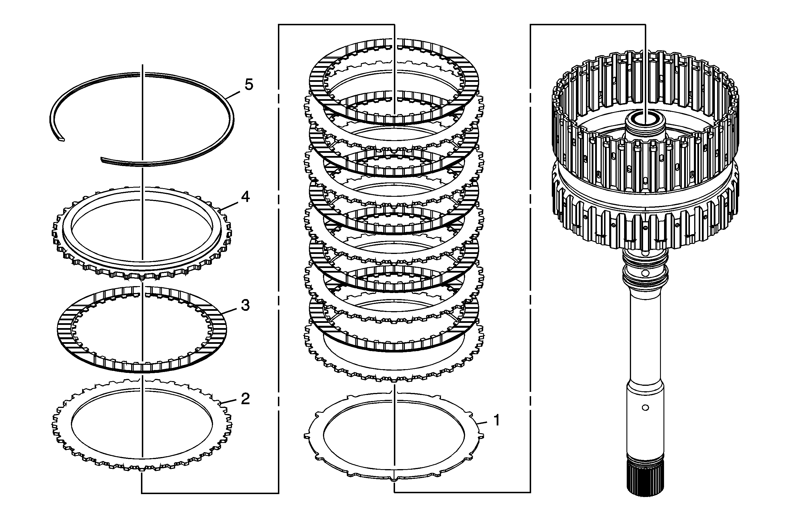
Callout | Component Name |
|---|---|
1 | 4-5-6 Clutch (Waved) Plate |
2 | 4-5-6 Clutch Plate (Qty: 6) |
3 | 4-5-6 Clutch Plate Assembly (Qty: 6) |
4 | 4-5-6 Clutch Backing Plate |
5 | 4-5-6 Clutch Backing Plate Retaining Ring Tip |
4-5-6 Clutch Overhaul 6L50
| Table 1: | 4-5-6 Clutch Plates Removal |
| Table 2: | 4-5-6 Clutch Piston Removal |
| Table 3: | Turbine Shaft Fluid Seal Ring Replacement |
| Table 4: | 4-5-6 Clutch Piston Installation |
| Table 5: | 4-5-6 Clutch Plates Installation |
4-5-6 Clutch Plates Removal
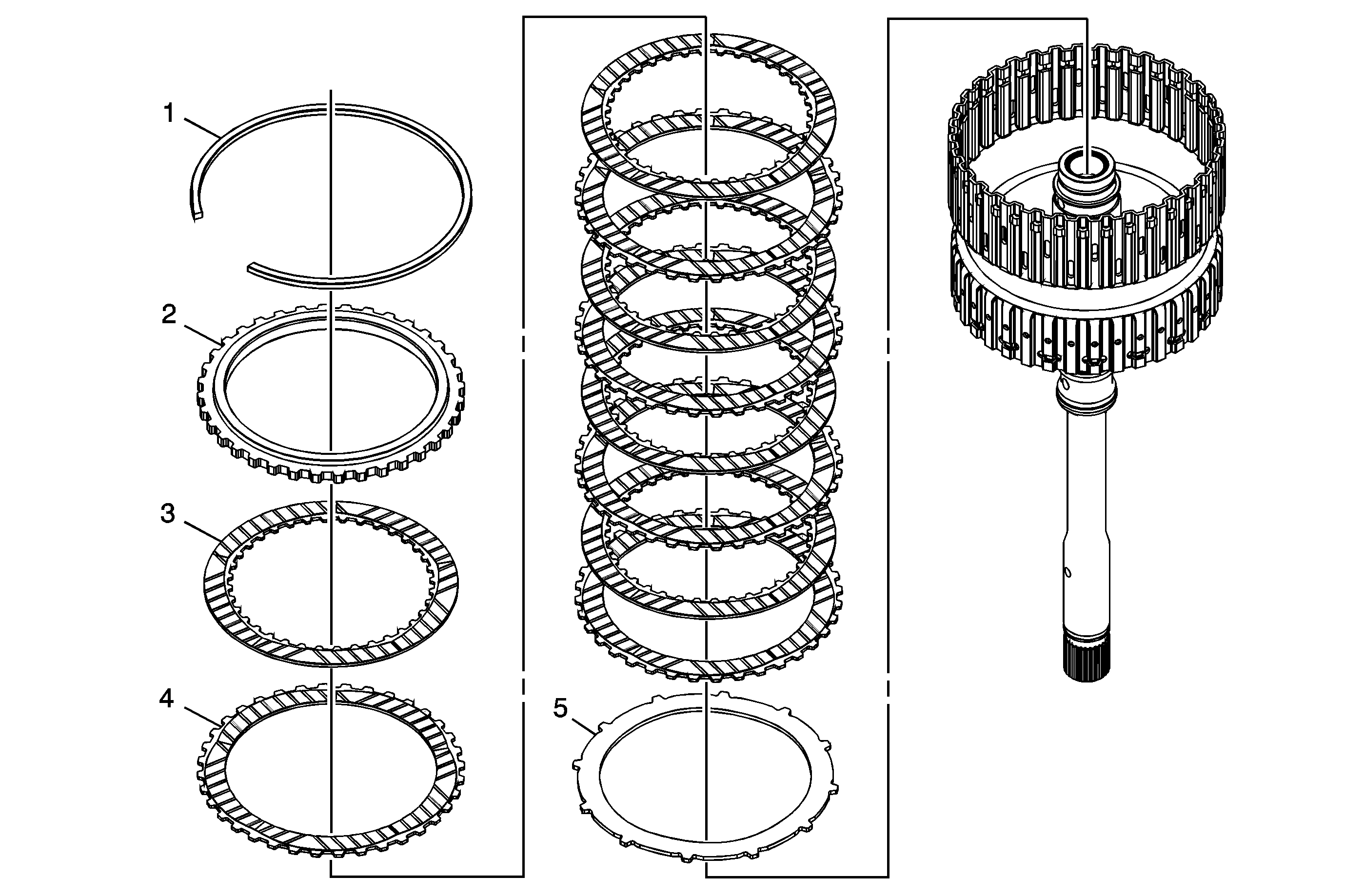
Callout | Component Name |
|---|---|
1 | 4-5-6 Clutch Backing Plate Retaining Ring |
2 | 4-5-6 Clutch Backing Plate |
3 | 4-5-6 Clutch Plate Assembly (Qty: 5) |
4 | 4-5-6 Clutch Plate (Qty: 5) |
5 | 4-5-6 Clutch (Waved) Plate |
4-5-6 Clutch Piston Removal

Callout | Component Name |
|---|---|
1 | 4-5-6 Clutch Piston Dam Retaining Ring Caution: Use care when compressing the 4-5-6 clutch piston assembly, spring and dam assembly. Compressing the dam assembly too much may damage it. Caution: Refer to Retaining Ring Reuse Caution in the Preface section. Special ToolJ 43074 Clutch Spring Compressor For equivalent regional tools, refer to Special Tools. |
2 | 4-5-6 Clutch Piston Dam Assembly Tip |
3 | 4-5-6 Clutch Spring |
4 | 4-5-6 Clutch Piston Assembly Tip |
Turbine Shaft Fluid Seal Ring Replacement

Callout | Component Name | ||||||
|---|---|---|---|---|---|---|---|
Preliminary Procedures
| |||||||
1 | Turbine Shaft Fluid Seal Ring (Qty: 3) Caution: Do not use old seal rings. Install NEW seal rings. Reusing old seal rings may cause internal transmission leaks and transmission damage. Caution: Size the fluid seal rings for at least 5 minutes after installation to obtain proper seal ring size. Failure to do so may cause internal transmission leaks and transmission damage. Tip Special Tools
For equivalent regional tools, refer to Special Tools. | ||||||
4-5-6 Clutch Piston Installation

Callout | Component Name |
|---|---|
1 | 4-5-6 Clutch Piston Assembly |
2 | 4-5-6 Clutch Spring Caution: Ensure the spring tabs are facing up during installation. Failure to do so may cause damage to the clutch assembly. |
3 | 4-5-6 Clutch Piston Dam Assembly Tip |
4 | 4-5-6 Clutch Piston Dam Retaining Ring Caution: Use care when compressing the 4-5-6 clutch piston assembly, spring and dam assembly. Compressing the dam assembly too much may damage it. Caution: Refer to Retaining Ring Reuse Caution in the Preface section. Tip Special ToolJ 43074 Clutch Spring Compressor For equivalent regional tools, refer to Special Tools. |
4-5-6 Clutch Plates Installation
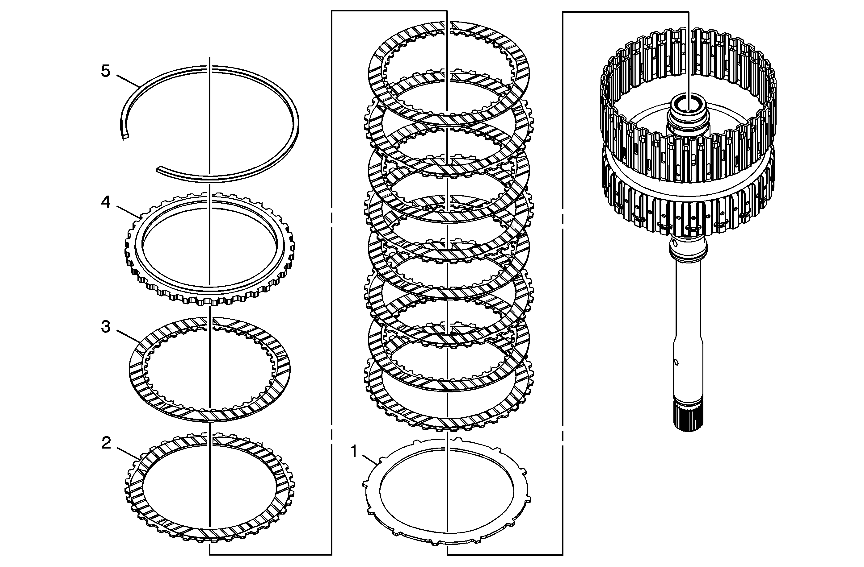
Callout | Component Name |
|---|---|
1 | 4-5-6 Clutch (Waved) Plate |
2 | 4-5-6 Clutch Plate (Qty: 5) |
3 | 4-5-6 Clutch Plate Assembly (Qty: 5) |
4 | 4-5-6 Clutch Backing Plate |
5 | 4-5-6 Clutch Backing Plate Retaining Ring Tip |
