For 1990-2009 cars only
Automatic Level Control Sensor and Bracket Replacement Front
Removal Procedure
- Raise and support the vehicle. Refer to Lifting and Jacking the Vehicle.
- Remove the tire and wheel. Refer to Tire and Wheel Removal and Installation.
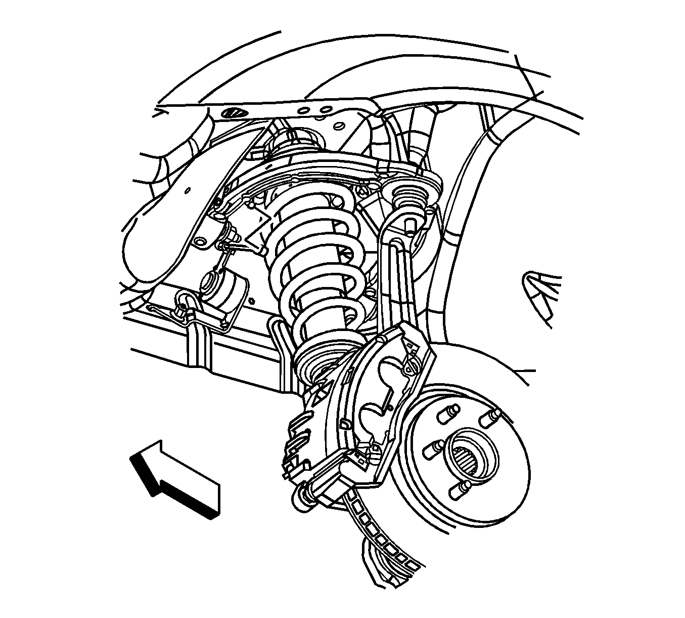
- Disconnect the front ride sensor link from the upper control arm ball stud.
- Disconnect the front ride sensor harness connector.
- Loosen the front ride sensor retaining nut.
- Gently tap the front ride sensor retaining stud in order to loosen the stud to fender connection.
- Remove the front ride sender from the vehicle.


Installation Procedure
- Position the sensor to the vehicle.
- Install the front ride sensor retaining nut and tighten to 9 N·m (80 lb in).
- Connect the front ride sensor link to the upper control arm ball stud.
- Connect the front ride sensor harness connector.
- Install the tire and wheel. Refer to Tire and Wheel Removal and Installation.
- Lower the vehicle.

Caution: Refer to Fastener Caution in the Preface section.

Automatic Level Control Sensor and Bracket Replacement Rear
Removal Procedure
- Raise and support the vehicle. Refer to Lifting and Jacking the Vehicle.
- Remove the tire and wheel. Refer to Tire and Wheel Removal and Installation.
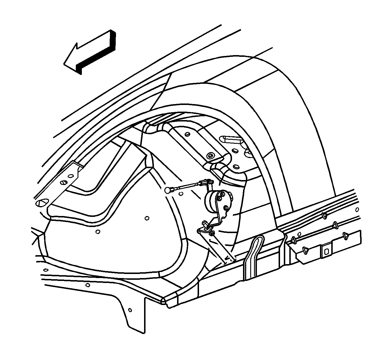
- Disconnect the rear ride sensor link from the upper control arm ball stud.
- Disconnect the rear ride sensor harness connector.
- Loosen the rear ride sensor retaining nut.
- Gently tap the rear ride sensor retaining stud in order to loosen the stud to fender connection.
- Remove the rear ride sender from the vehicle.

Installation Procedure
- Install the sensor to the vehicle.
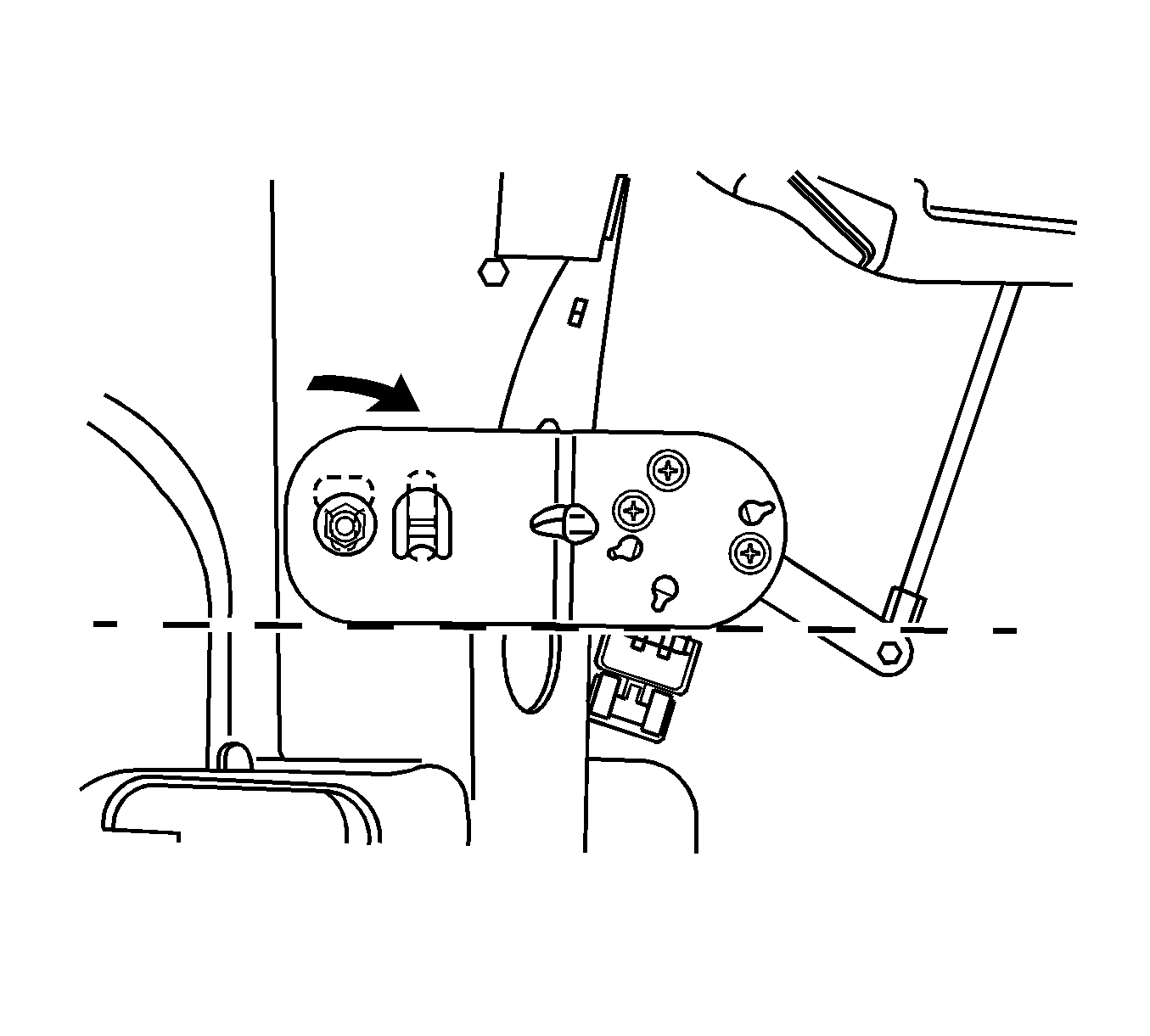
- Bottom out the captured stud in the key hole.
- Rotate the sensor and bracket until the tab on the bracket bottoms out in the slot.
- If the sensor bracket is not yet level, continue to rotate it allowing the captured stud to lift slightly from the bottom of the keyhole, until the sensor is level.
- Install the rear ride height sensor retaining nut and tighten to 9 N·m (80 lb in).
- Connect the ride sensor link to the upper control arm ball stud.
- Connect the ride sensor harness connector.
- Install the tire and wheel. Refer to Tire and Wheel Removal and Installation.
- Lower the vehicle.

Caution: Refer to Fastener Caution in the Preface section.
