Removal Procedure
Caution:
| • | Remove the fuel rail assembly carefully in order to prevent damage to the injector electrical connector terminals and the injector spray tips. Support the fuel rail after the fuel rail is removed in order to avoid damaging the fuel rail components. |
| • | Cap the fittings and plug the holes when servicing the fuel system in order to prevent dirt and other contaminants from entering open pipes and passages. |
- Relieve the fuel system pressure. Refer to
Fuel Pressure Relief.
- Remove the front and rear section of the supercharger inlet duct assembly. Refer to
Supercharger Inlet Duct Assembly Replacement.
Warning: Wear safety glasses when using compressed air in order to prevent eye injury.
- Clean the fuel rail and injector ports on the supercharger with compressed air.
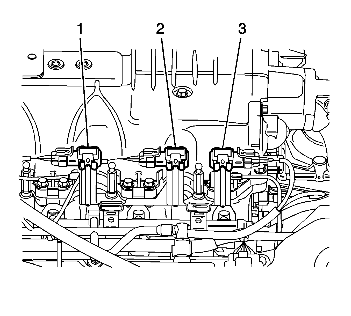
- Disconnect the electrical connectors from the following sensors:
| • | The supercharger inlet absolute pressure (SCIAP) sensor (1) |
| • | The barometric pressure (BARO) sensor (2) |
| • | The manifold absolute pressure (MAP) sensor (3) |
- Disconnect the vacuum lines from the MAP and SCIAP sensors.
- Remove the SCIAP, BARO and MAP sensors with the bracket.
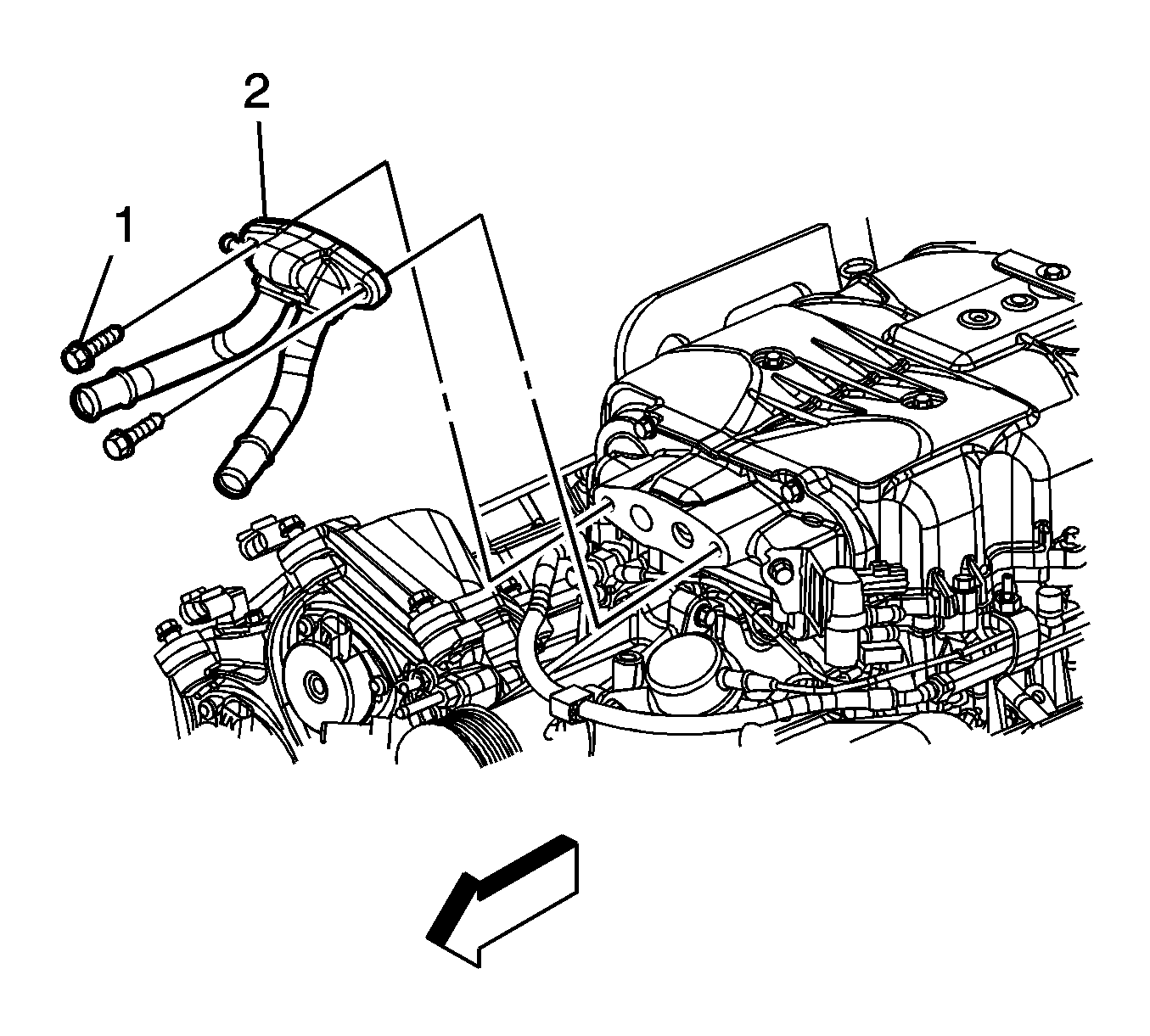
- Partially drain the charge air cooling system. Refer to
Charge Air Cooling System Draining and Filling.
- Remove the front section of the charge air cooler front manifold assembly (2). It is not necessary to remove the hoses from the manifold pipes. position the manifold with hoses aside to allow for removal of the fuel rail assembly. Refer to
Charge Air Cooler Front Manifold Replacement.
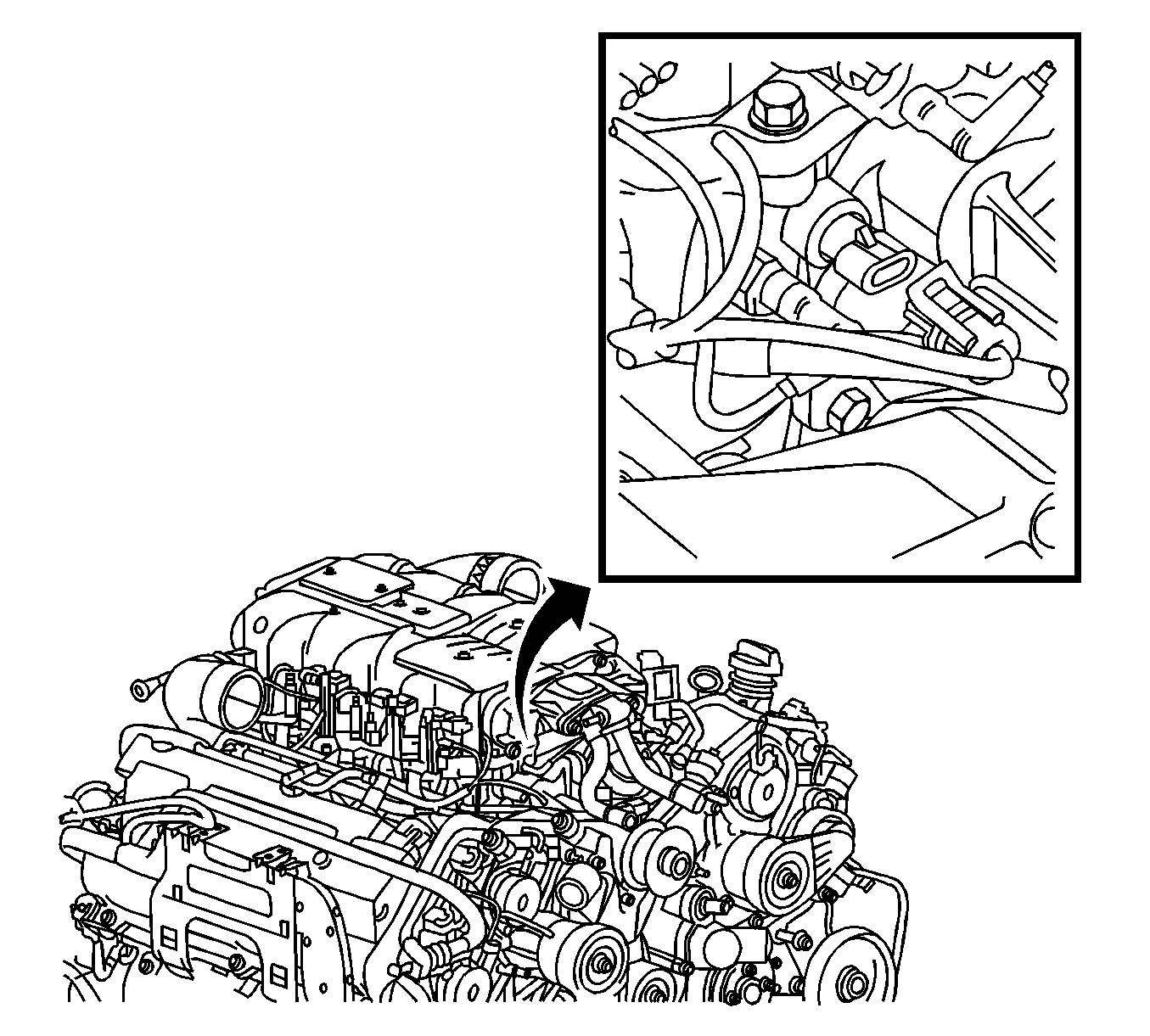
- Disconnect the electrical connector from the air inlet temperature 2 sensor and position aside.
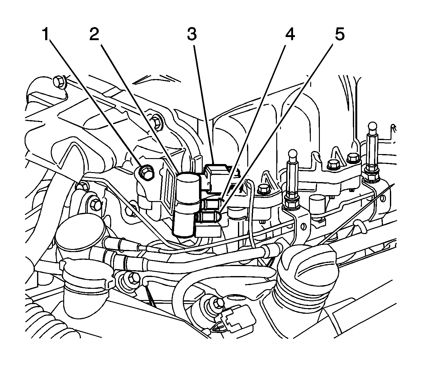
- Disconnect the supercharger bypass solenoid valve electrical connector (3) and position the harness aside.
- Disconnect the vacuum line from the supercharger actuator valve and position the line aside.
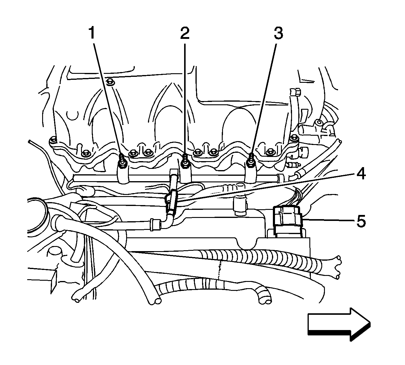
- Disconnect the engine compartment fuel line fitting (4) from the fuel rail. Refer to
Metal Collar Quick Connect Fitting Service.
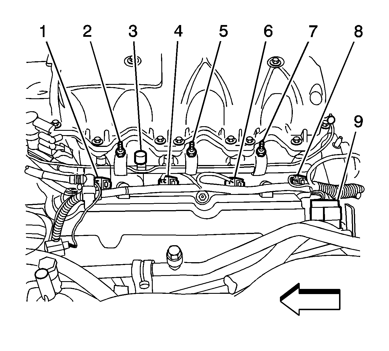
- Disconnect the fuel injector electrical connectors (1, 4, 6, 8) from the left and right side of the engine.
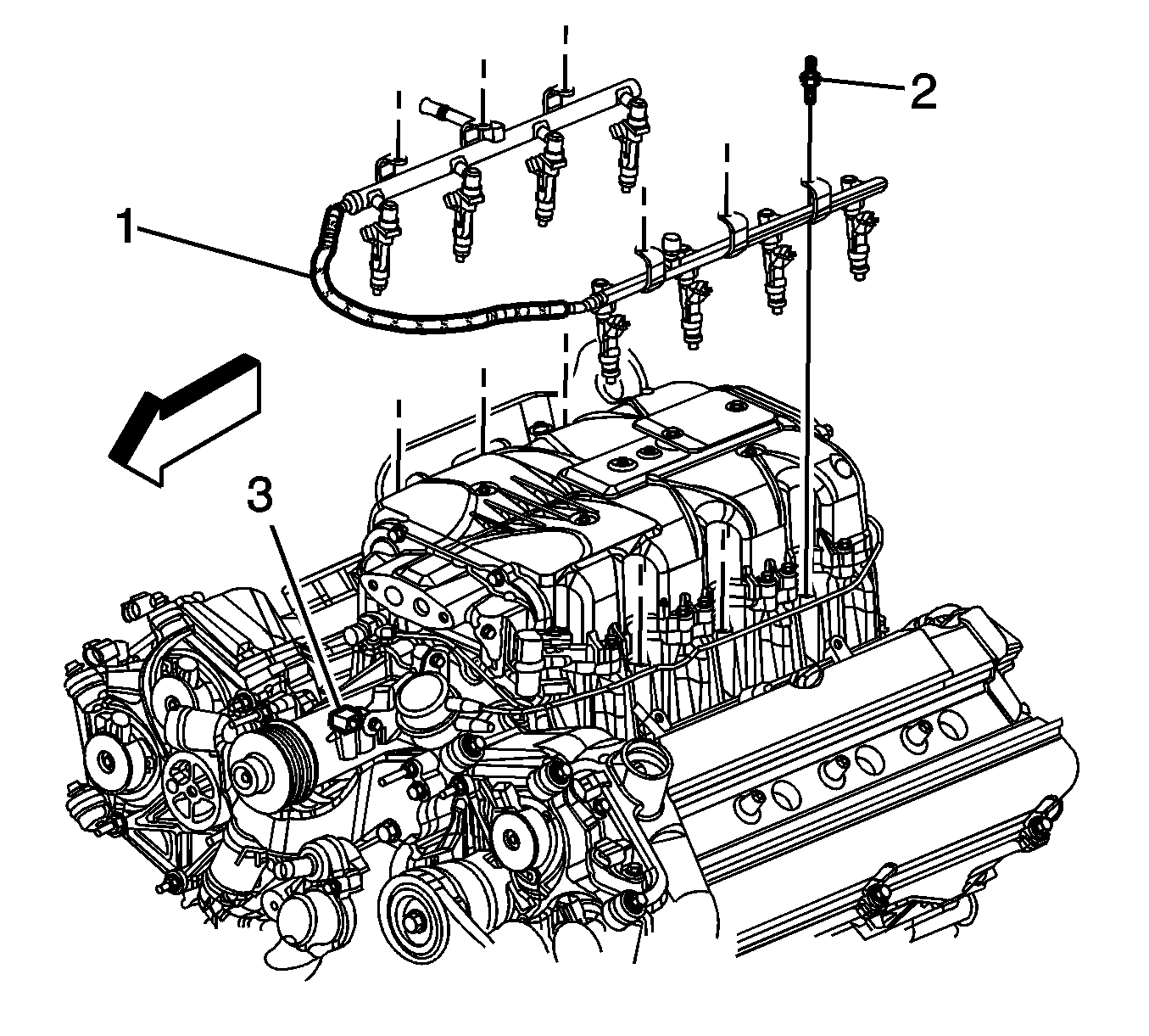
- Open the clip (3) that secures the fuel rail jumper to the front of the supercharger.
- Remove the fuel rail attaching studs (2).
- Remove the fuel rail assembly (1) from the supercharger.
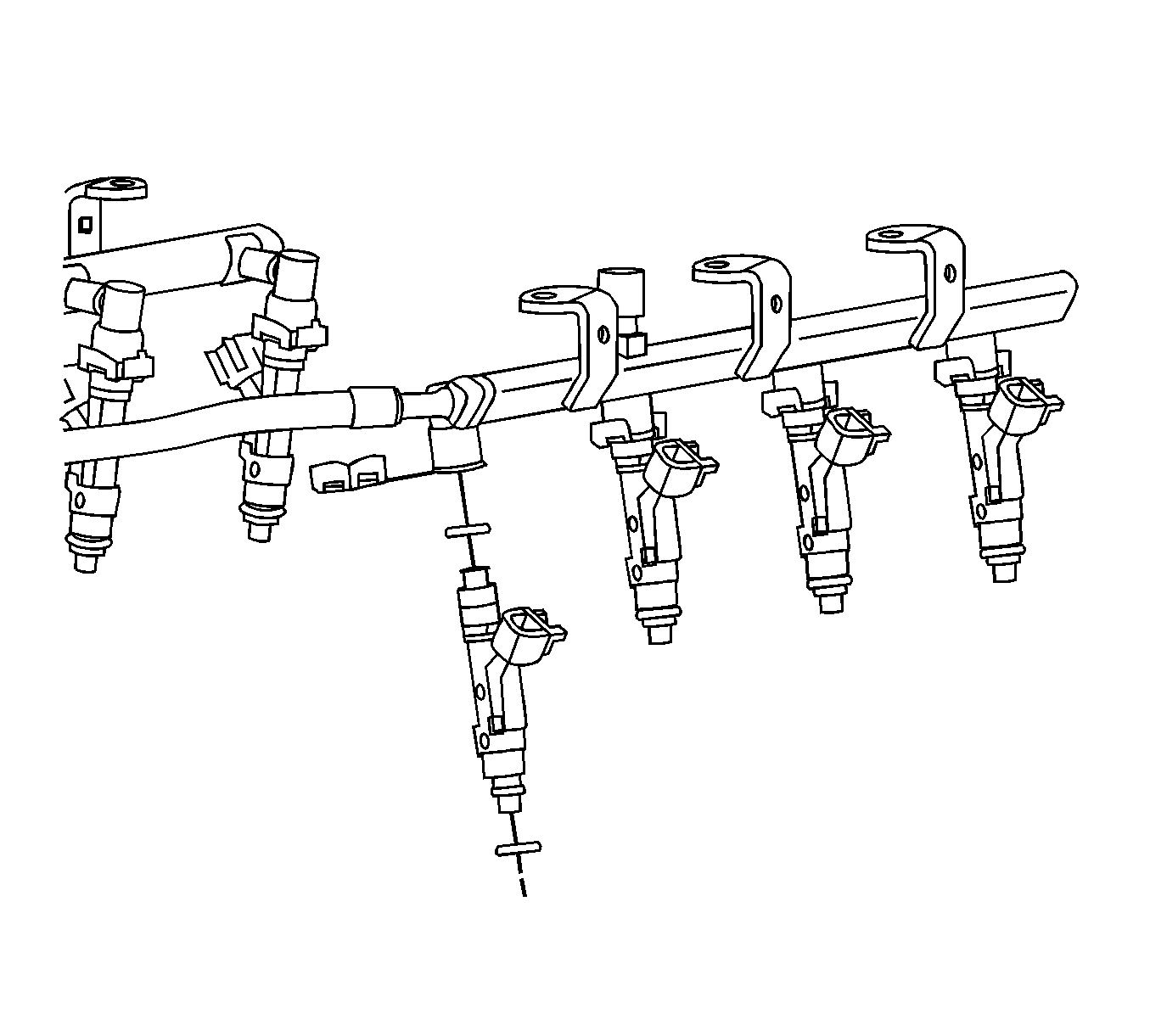
- Remove the injector lower O-ring seal from the spray tip end of each injector.
- Discard the O-ring seals.
- Remove the retainers from the fuel injectors if fuel injector removal is necessary.
- Remove the fuel injectors from the fuel rail.
- Remove the O-ring seals from the fuel injectors. Discard the O-ring seals.
Installation Procedure
Caution:
| • | Use care when servicing the fuel system components, especially the fuel injector electrical connectors, the fuel injector tips, and the injector O-rings. Plug the inlet and the outlet ports of the fuel rail in order to prevent contamination. |
| • | Do not use compressed air to clean the fuel rail assembly as this may damage the fuel rail components. |
| • | Do not immerse the fuel rail assembly in a solvent bath in order to prevent damage to the fuel rail assembly. |

- If the injectors were removed from the fuel rail, lubricate the new fuel injector O-ring seals with clean engine oil.
- Install the new fuel injector O-ring seals on to the fuel injectors.
- Install the fuel injectors to the fuel rail using new retainer clips.
- Ensure that the injectors are aligned by orientating the electrical connectors perpendicular to the crankshaft centerline.
- Lubricate and install the new O-ring seals on the spray tip end of each injector.

- Align the fuel injectors and fuel rail to the supercharger assembly.
- Carefully press the fuel rail assembly (1) downward until fully seated.
Caution: Refer to Fastener Caution in the Preface section.
- Install the fuel rail attaching studs (2) and tighten to
10 N·m (89 lb in).
- Install the fuel rail to the clip (3) on the front of the supercharger.

- Connect the fuel injector electrical connectors (1,4,6,8) to the left and right side of the engine.

- Connect the engine compartment fuel line fitting (4) to the fuel rail. Refer to
Metal Collar Quick Connect Fitting Service.

- Connect the vacuum line to the supercharger actuator valve.
- Connect the supercharger bypass solenoid valve electrical connector (3).

- Connect the electrical connector to the air inlet temperature 2 sensor.

- Install the front section of the charge air cooler front manifold assembly (2). Refer to
Charge Air Cooler Front Manifold Replacement.

- Install the SCIAP (1), BARO (2) and MAP (3) sensors with the bracket.
- Connect the vacuum lines to the MAP (3) and SCIAP (1) sensors.
- Connect the electrical connectors to the following sensors:
- Install the front and rear section of the supercharger inlet duct assembly. Refer to
Supercharger Inlet Duct Assembly Replacement.
- Install the fuel fill pipe cap.
- Fill the charge air cooling system with coolant. Refer to
Charge Air Cooling System Draining and Filling.
- Check the fuel system for leaks.
- Install the engine sight shield. Refer to
Intake Manifold Sight Shield Replacement.


