DIESEL FUEL LINE HEATER SYSTEM INSTALLATION

Cadillac is now making available, at the owner's expense, a diesel fuel line heater system kit. Owners may wish to consider dealer installation of this system based upon temperature conditions in their local areas. The kit can be installed on all current and past model diesels equipped with a water-in-fuel sensing system except 1978 and 79 Sevilles (the kit cannot be installed on these vehicles due to the fuel tank design).
To perfom a fuel line heater installation, it will be necessary to order a heater kit and a fuel tank filter with check valve under P/N 22514576 (kit) and P/N 5651973 (in-tank fuel filter).
The suggested Labor Time for the installation of the kit is .5 hrs. with an additional .8 hrs. to install the in-tank filter. The following is the recommended installation procedure:
FUEL LINE HEATER INSTALLATION PROCEDURE
1. Disconnect the negative cables from both batteries.
2. Remove the air cleaner and install the protective cover on the air crossover.
3. Remove the rear A/C compressor brace to intake manifold.
4. Disconnect the T.V. cable at the bellcrank and disconnect the T.V. cable bracket. Move it over the top of the fuel pipe.
5. Disconnect and move out of the way all vacuum hoses and electrical wires that are routed over the top of the fuel pipe.
6. Remove the crankcase ventilation pipe on the right side of the engine.
7. On 1980-81 models, disconnect the fuel return line pipe from the injection pump and move to the side.
8. Remove the fuel pipe that runs between the pump and filter. (On some models, it may help to cut the pipe to remove it.)
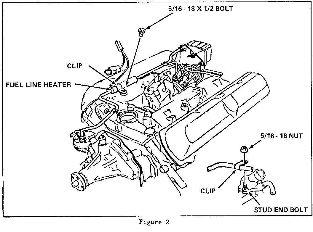
9. Install a stud bolt in the right hand side of the thermostat cover/water outlet. Most 1981's will have the stud bolt installed. (See Fig. 2)
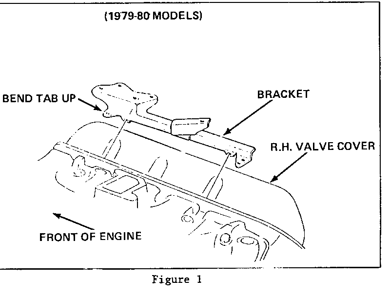
10. On 1979-80 models, bend the tab holding the electrical sheath on the right hand valve cover up to a 450 angle (Fig. 1).
11. Install the heater and pipe assembly and both clips (Fig. 2). It may be necessary to loosen the wing nut on the filter to start the threads.
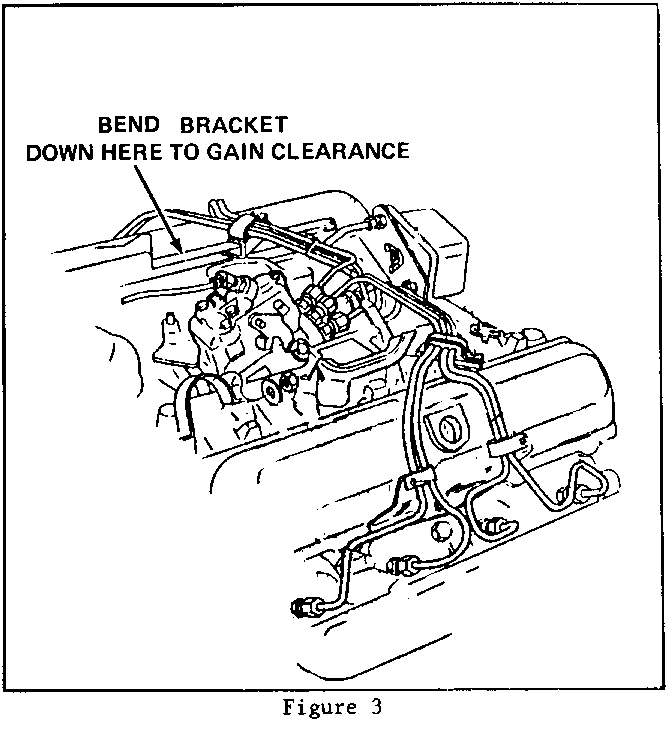
NOTICE: If there is not at least a 1/32 inch clearance between the fuel line and the injection line bracket, perform the following until the clearance is obtained. Do not bend the fuel line -- damage to the heater may occur. Loosen the right hand side of the fuel filter bracket. Put a 1/8 inch front end shim under the bracket to raise it up. Bend the bracket down as shown in Fig. 3. Pry the fuel heater up by inserting a screwdriver under the heater clamp and prying upwards.
12. Reconnect the fuel return line to the 1980-81 injection pump.
13. Use a tie strap and fasten the electrical wire sheath to the injection lines on the right hand valve cover.
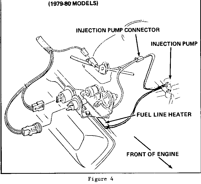
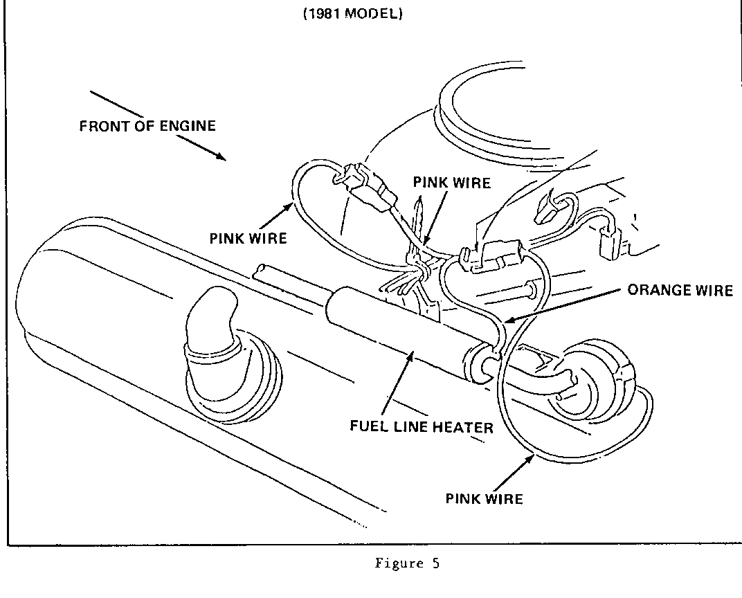
14. On 1979-80 cars, disconnect the fuel pump solenoid and connect the female electrical connector from the fuel heater to the injection pump fuel solenoid. Connect the fuel solenoid connector to the pigtail on the fuel line heater (Fig. 4). On 1981 models, disconnect the connector in the EGR switch lead, connect the fuel line heater into this circuit as shown in Fig. 5.
15. Reconnect all vacuum lines and electrical wires.
16. Reconnect the T.V. cable bracket and hook the T.V. cable to the bellcrank.
17. Reinstall the rear A/C compressor brace.
18. Reconnect the negative battery cables, start the engine, and check for leaks.
19. Reinstall the air cleaner.
FUEL TANK FILTER INSTALLATION PROCEDURE
1. Remove fuel tank, per Service Manual Procedures.
2. Remove the fuel tank sending unit. If sending unit filter already has a check valve, proceed to step 6.
3. Secure the tank sender unit in a vise just below where the float assembly is welded to the pickup tube.
4. Place a 7/16 inch open end wrench around the metal sleeve of the filter. Remove the filter by tapping with a small mallet against the wrench. Remove tank sender from the vise.
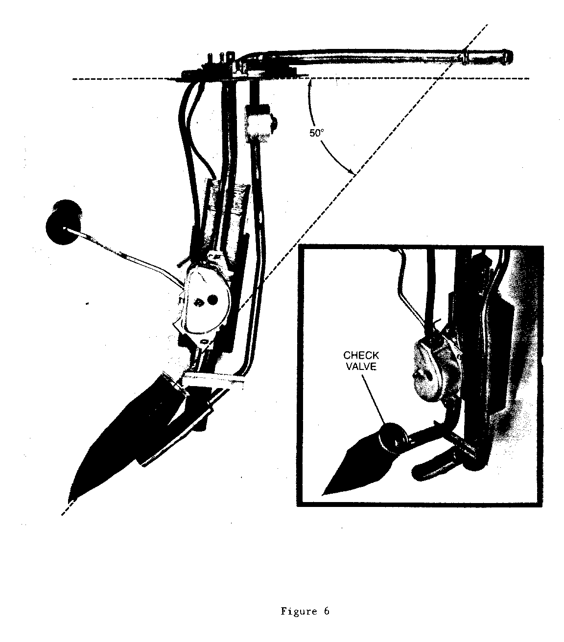
5. Install the filter at a 500 angle to perpendicular (refer to Fig. 6) with check valve at top.
NOTICE: Filter should not contact sharp edges when being installed to prevent damage.
6. Reinstall the tank sender unit.
7. Reinstall the fuel tank.
General Motors bulletins are intended for use by professional technicians, not a "do-it-yourselfer". They are written to inform those technicians of conditions that may occur on some vehicles, or to provide information that could assist in the proper service of a vehicle. Properly trained technicians have the equipment, tools, safety instructions and know-how to do a job properly and safely. If a condition is described, do not assume that the bulletin applies to your vehicle, or that your vehicle will have that condition. See a General Motors dealer servicing your brand of General Motors vehicle for information on whether your vehicle may benefit from the information.
