HARSH UPSHIFT/SLIP BUMP NEW PARTS SERVICE KIT

MODELS AFFECTED: 1982-1983 ELDORADO, SEVILLE, DEVILLE AND BROUGHAM
1982 and 1983 Cadillacs equipped with THM 200-4R or 325-4L transmissions may experience harsh 1-2 and/or 3-4 upshifts at any throttle position. This condition may result from sticking accumulator pistons due to excessively smooth or glazed over bores in the accumulator housing. Additionally, on Eldorado and Seville models equipped with an HT4100 engine and THM 325-4L model "AJ" transmission, this condition may result from a mispositioned accumulator valve return spring in the control valve body assembly.
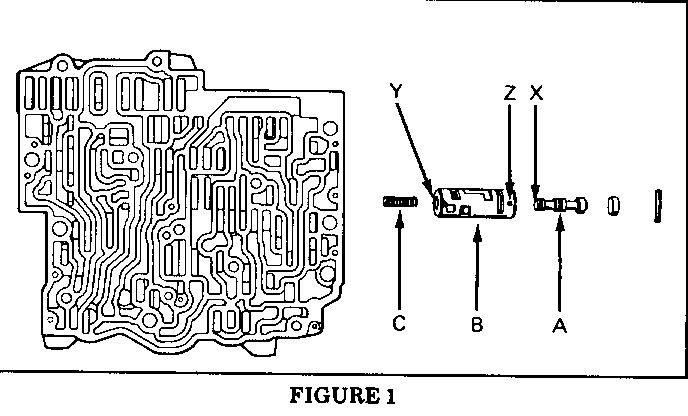
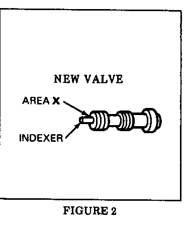
The accumulator valve return spring condition is caused by accumulator valve movement (refer to Figure 1). Normal accumulator valve travel allows the valve (part "A") to protrude through the accumulator valve bushing (part "B"). When this occurs, the return spring (part "C") can become mispositioned and catch on the bushing end. A recent production change includes a spring indexer on the end of the valve (refer to Figure 2, area "X"). Past models can be repaired by installing a service kit containing a new design valve and bushing.
When servicing THM 200-4R or THM 325-4L transmissions for harsh 1-2 and/or 3-4 upshifts, refer to the following service procedure.
Service Procedure
1. Remove the oil pan per Section 7A of the 1983 Service Information Manual (SIM).
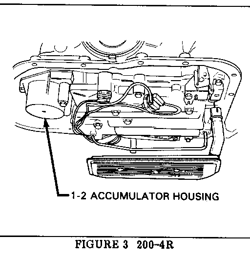
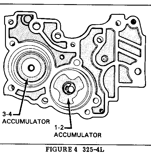
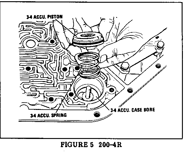
2. Remove the accumulator housing (refer to Figures 3 and 4) following instructions outlined in the appropriate SIM unit repair section. On THM 200-4R models, it is also necessary to remove the control valve body assembly and spacer plate to gain access to the 3-4 accumulator bore located in the transmission case (refer to Figure 5).
3. Using a brake cylinder hone and solvent, hone the accumulator bores to a smooth, dull finish. Clean thoroughly before reassembly. On THM 325-4L model "AJ" transmissions, proceed with the following steps prior to reassembly.
4. Remove the control valve body assembly. Remove the accumulator valve, bushing, and spring (refer to Figure 1, also refer to Figure 325-4L-228 in the 1983 SIM).
5. Install a new design valve and bushing contained in service kit, P/N 8635969. When reassembling, be sure to position the bushing in the control valve assembly with the square locator pin hole (refer to Figure 1, area "Z") pointing up.
For warranty purposes, use labor Operation No. K6660 at 1.1 hours for THM 200-4R and 1.5 hours for THM 325-4L.
CONTROL VALVE ASSEMBLY WffH ACCUMULATOR VALVE TRAIN
A Accumulator Valve B Accumulator Valve Bushing C Accumulator Valve Return Spring X Valve Land End, changed to iclude a spring indexer Y Bushing area to be chamfered Z Square Locating Hole, position upward for reassembly
General Motors bulletins are intended for use by professional technicians, not a "do-it-yourselfer". They are written to inform those technicians of conditions that may occur on some vehicles, or to provide information that could assist in the proper service of a vehicle. Properly trained technicians have the equipment, tools, safety instructions and know-how to do a job properly and safely. If a condition is described, do not assume that the bulletin applies to your vehicle, or that your vehicle will have that condition. See a General Motors dealer servicing your brand of General Motors vehicle for information on whether your vehicle may benefit from the information.
