SERVICE MANUAL UPDATE FOR 1988 'K' TOURING SEDAN (STS) W/4.5L

MODELS AFFECTED: 1988-1/2 STS SEVILLE
The service information for the 1988-1/2 STS Seville was not included in the 1988 Body Service Manual. This bulletin provides that information and is intended to supplement the Body Service Manual.
The following is a list of items unique to the STS package:
Exterior:
-------- - New color - white diamond
- Car colored front lower air dam
- Modified front fender: - Cornering lamp moved to fascia - Headlamp monitors eliminated
- New grille with flush-mounted wreath and crest
- STS nameplate for rear compartment lid
- New car color body side moldings
- Car colored outside rearview mirrors with black patch
- New cloisonne rear compartment lid lock cover
- Export license plate pocket
- Modified export tail lamps with three color European-style lens includes back-up lamps
Interior:
-------- - Color and trim:
- Medium beechwood ultra-soft leather and medium beechwood thaxton floor carpet (also on instrument panel)
- Thaxton floor mats - positively attaching front and rear
- Burl elm high gloss wood on door trim panels, horn pad, horn bar, instrument panel and front/rear console
- Leather wrapped front/rear door trim panels
- New ultra-soft leather front seats with net type map pockets: - Powered six-way seat adjusters - Recliners - Contours - Lumbar supports - Manual articulating headrests
- Rear seat design change: - Bucket seat appearance with center console in ultra-soft leather and rear stowage compartment between seats
- Rear compartment lid liner in tara carpet with STS logo
INDEX
Manual sections included in this bulletin are:
Bumpers.................................................... 2B Chassis Sheet Metal........................................ 2C General Body Service Procedures........................... 10-1 Doors...................................................... 10-5 Body Rear End.............................................. 10-7 Seats...................................................... 10-9
SECTION 2B BUMPERS
CONTENTS
Front Bumper Removal and Installation...................... 2B-1 Front Bumper Disassembly and Assembly..................................................... 2B-1 Front Bumper Guard Removal and Installation................................................. 2B-1 Front Lower Air Dam Removal and Installation................................................. 2B-3 Cornering and Side Marker Lamp Molding Removal and Installation............................. 2B-3 Cornering and Side Marker Lamp Removal and Installation..................................... 2B-3 Rear Reflector Removal and Installation................................................. 2B-4
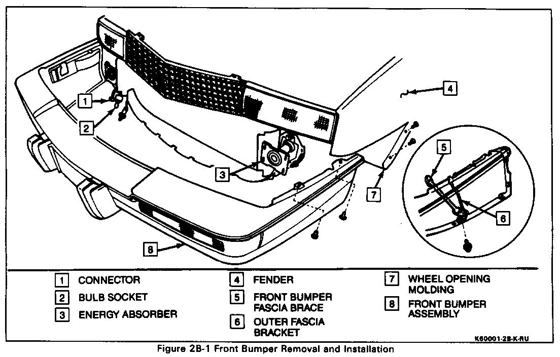
FRONT BUMPER (Figure 2B-1) ------------- Remove or Disconnect -------------------- 1. Negative Battery Cable
2. Four screws (two on each side) securing wheel opening molding (7) to front bumper assembly (8).
3. Two bolts (one on each side) securing outer fascia bracket (6) to front bumper fascia brace (5).
4. Left and right side marker lamps (see procedure).
5. Four screws (two on each side) securing front bumper fascia to fender (4). Access through side marker lamp holes.
6. One bulb socket (2) and one side connector (1) at each turn signal lamp.
7. Eight nuts (four on each side) securing bumper (8) to energy absorbers (3).
8. Front bumper (8) by pulling straight out.
Install or Connect
1. Have a helper position the front bumper (8) to achieve the gaps shown in section 2C, "Sheet Metal Tolerances," of the 1988 Body Service Manual. Install eight nuts (four on each side) at energy absorbers (3).
2. One bulb socket (2) and one connector (1) at each turn signal lamp.
3. Four screws (two on each side) securing front bumper fascia to fender (4). Access through side marker lamp holes.
4. Left and right side marker lamps (see procedure).
5. Two bolts (one on each side) securing outer fascia bracket (6) to front bumper fascia brace (5).
6. Four screws (two on each side) securing wheel opening molding (7) to front bumper (8).
7. Negative battery cable.
Front Bumper Disassembly (Figure 2B-2) ------------- Remove or Disconnect -------------------- 1. Both fascia outer brackets (1) from front bumper fascia (4).
2. Four nuts (two on each side) and both front bumper guards (9) using a 13mm socket.
3. Eight nuts (four on each side) and moldings (8) around both parking/turn signal lamps (7) using a 10mm socket.
4. Two screws (one on each side) and both parking/tum signal lamps (7).
5. Four nuts and front license bracket (10) using a 10mm socket.
6. Two nuts securing fascia (4) to impact bar (3) assembly using a 10mm socket.
7. Separate fascia (4) from impact bar (3) (two sided tape) at top using a screwdriver.
8. Fascia (4) from impact bar (3).
Install or Connect
1. Impact bar (3) to fascia (4)
2. Two nuts securing fascia (4) to impact bar (3) using a 10mm socket. Press down on two sided tape.
3. Front License bracket (10) and secure with four nuts using a 10mm socket.
4. Parking/tum signal lamps (7) into bumper and secure with two screws (one on each side).
5. Moldings (8) around both parking/tum signal lamps (7) and secure with eight nuts (four on each side) using a 10mm socket.
6. Both front bumper guards (9) and secure with four nuts (two on each side) using a 13mm socket.
7. Both fascia outer brackets (1) into front bumper fascia.
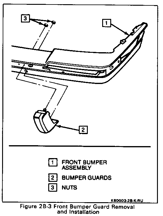
FRONT BUMPER GUARD (Figure 2B-3) ------------- Remove or Disconnect -------------------- 1. Two nuts (3) securing bumper guard (2) using a 13mm socket.
2. Front bumper guard (2).
Install or Connect
1. Position front bumper guard (2).
2. Two nuts (3) securing front bumper guard (2) using a 13mm socket and Installation
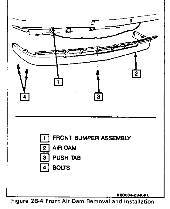
FRONT LOWER AIR DAM (Figure 2B-4) ------------- Remove or Disconnect -------------------- 1. Four bolts (4) (two on each side) securing air dam (2) to each side of front bumper (1).
2. Eight push tabs (3) securing air dam (2) to front bumper (1).
3. Six clips and rubber shroud from air dam (2).
4. Air dam (2).
Install or Connect
1. Position air dam (2) and secure to front bumper (1) with eight pushtabs (3).
2. Six clips and rubber shroud to air dam (2).
3. Four bolts (4) (two on each side). securing each side of air dam (2) to front bumper (1).
CORNERING AND SIDE MARKER LAMP MOLDING
(Figure 2B-5)
Remove or Disconnect
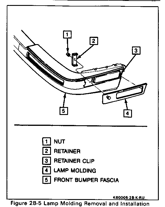
1. Nut (1) and retainer (2) securing molding (4) to front bumper with a 10mm socket.
2. Pull molding (4) out and forward and unclip at rear (3).
Install or Connect
1. Push molding into clip at rear (3) and position into bumper.
2. Retainer (2) and nut (1) securing molding (4) to front bumper using a 10mm socket.
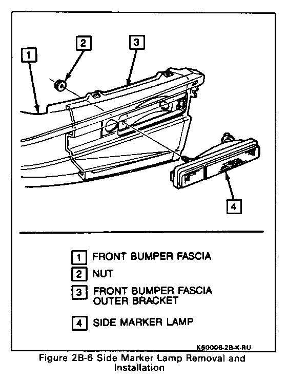
CORNERING AND SIDE MARKER LAMP
(Figure 2B-6)
Remove or Disconnect
1. Cornering and side marker lamp molding (see procedure).
2. Nut (2) securing lamp (4) to bumper using a 10mm socket.
3. Carefully work lamp (4) out of bumper.
4. Two bulbAockets. Twist bulb socket counterclockwise and pull out.
Install or Connect
1. Two bulb/sockets into lamp (4). Push in and turn clockwise.
2. Carefully work lamp (4) into bumper.
3. Nut (2) securing lamp (4) to bumper using a 10mm socket.
4. Cornering and side marker lamp molding (see procedure).
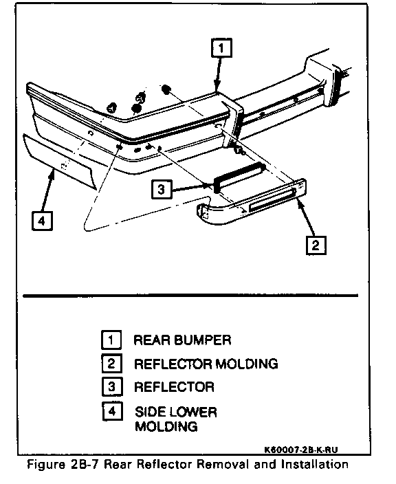
REAR REFLECTOR (Figure 2B-7) ------------ Remove or Disconnect -------------------- 1. Two nuts securing lower side molding (4) to rear bumper (1) using a 10mm socket. Unclip at front and remove molding (4).
2. Two nuts securing reflector molding (2) using a 10mm socket.
3. Two bolts and reflector (3).
Install or Connect
1. Reflector (3) to molding (2) with two bolts.
2. Reflector molding (2) to bumper (1) and secure using two nuts and a 10mm socket.
3. Slide molding (4) into rear bumper (1). Clip at front and install nut using a 10mm socket.
SECTION 2C CHASSIS SHEET METAL ------------------- CONTENTS
Grille Removal and Installation................................. 2C-1 Grille Disassembly and Assembly................................. 2C-1
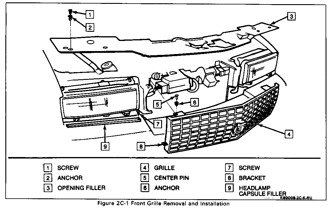
GRILLE (Figure 2C-1) -------------
Remove or Disconnect
1. Open hood.
2. Four plastic screws (1) and anchors (2) securing radiator/grille opening filler (3). Remove opening filler (3).
3. Two plastic screws (7) at each side of grille (4) securing headlampcapsule filler (9) to bracket (8).
4. Four grille retainers. Pull center pin (5) out and remove with anchor (6)
Install or Connect
1. Position grille (4) and secure using four grille retainers. Push in anchor (6) and then center pin (5).
2. Two plastic screws (7) at each side of grille (4) securing headlamp capsule filler (9) to bracket (8).
3. Position radiator/grille opening filler (3) and secure with four plastic anchors (2) and screws (1).
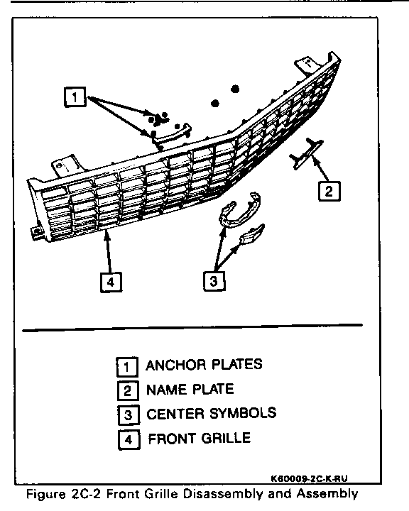
GRILLE DISASSEMBLY (Figure 2C-2) ------------- Remove or Disconnect -------------------- 1. Four nuts behind center symbols (3). 2. Two anchor plates (1) 3. Center Symbols (3). 4. Two nuts and "CADILLAC" nameplate (2).
Install or Connect
1. Position "CADILLAC" nameplate (2) and secure with two nuts.
2. Position two center symbols (3) and secure with two anchor plates (1) and four nuts.
SECTION 10-1 GENERAL BODY SERVICE PROCEDURES -------------------------------- CONTENTS
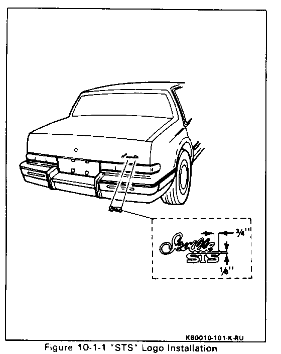
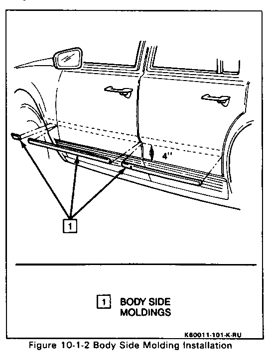
Seville STS Logo and Body Side Molding Removal and Installation........10-1-1
SEVILLE STS LOGO AND BODY SIDE MOLDINGS (Figures 10-1-1 and 10-1-2) ---------------------------
Remove or Disconnect
When removing or installing any body exterior molding, emblem or nameplate, care should be exercised:
- Adjacent finishes should be covered to prevent damage to the finish.
- Proper tools and care should be used to guard against molding damage.
- When a molding is overlapped, the overlapping molding must be partially disengaged or removed first.
Install or Connect
The STS logo and body side moldings are attached with adhesive tape. Use the following procedure to insure a good molding replacement.
1. Wash affected panel area with soap and water and wipe dry. Remove all traces of adhesive from body panel and back of molding using oil-free naphtha or alcohol.
2. Mark proper position of molding with a length of masking tape. Use adjacent moldings as a guide, if applicable.
3. Use a heat gun to heat surface where logo(s) are to be installed. The panel surface should be 2l DEG. C to 32 DEG. C or 70 DEG. F to 90 DEG. F.
4. Align logo or molding as shown and apply tape as a guide.
5. Peel backing off of logo or molding and press into place.
SECTION 10-5 DOORS ----- CONTENTS
Front Door Trim Panel Removal and Installation .................................................10-5-1 Rear View Exterior Mirror Removal and Installation ............................................ 10-5-2 Rear Door Trim Panel Removal and Installation ................................................ 10-5-3
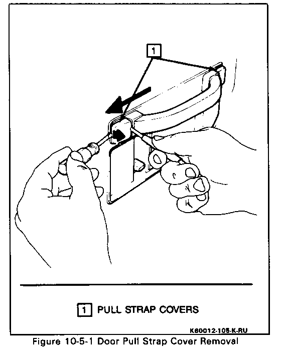
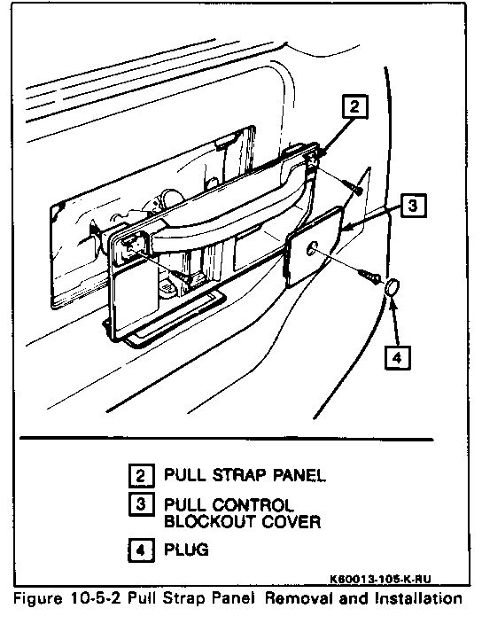
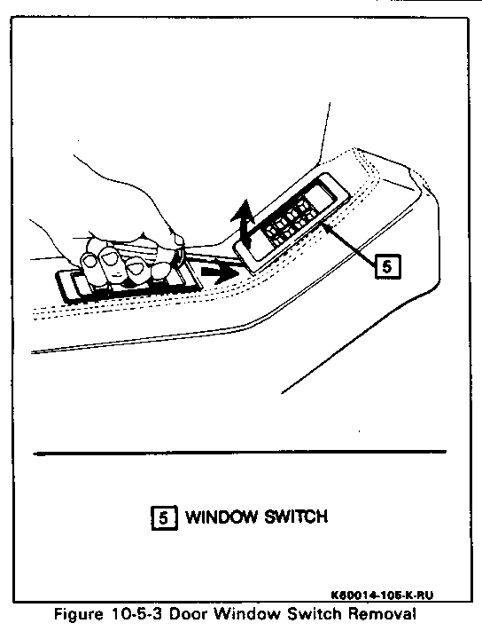
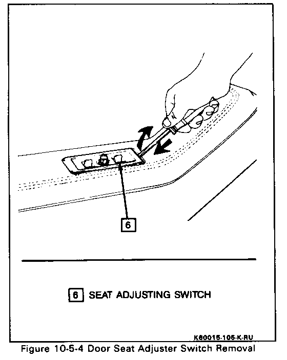
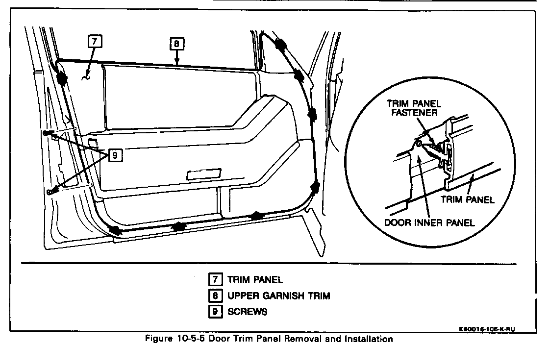
FRONT DOOR TRIM PANEL (Figures 10-5-1 thru 10-5-5) ----------------------------
Remove or Disconnect
1. Negative battery cable.
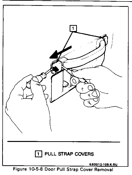
2. Both pull strap covers (1). Use two small screwdrivers and carefully pry and slide off as shown.
3. Two screws at pull strap.
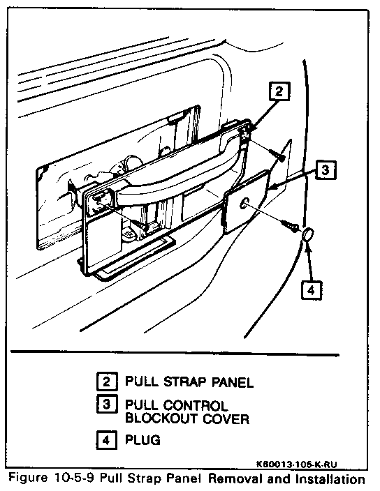
4. Plug (4), screws and pull control blockout cover (3).
5. Pull strap panel (2). Unplug connector at lock switch.
6. Window switch (5). Using a screwdriver, carefully push in and pull up as shown. Unscrew knob and disconnect electrical connector.
7. Seat adjusting switch (6). Using a screwdriver, carefully push in and pull up as shown. Disconnect electrical connector.
8. Two screws (9) at rear of trim panel (7).
9. Trim panel (7) using tool J-2459B or equivalent to disengage fasteners on trim panel from holes in door. Disconnect speaker, courtesy lamp and waming lamp electrical connectors.
10. Six screws and upper gamish trim (8).
Install or Connect
1. Upper garnish trim (8) and secure with six screws.
2. Speaker, courtesy lamp and waming lamp electrical connectors to trim panel.
3. Trim panel (7). Align fasteners to holes in door and push in on trim panel.
4. Two screws (9) at rear of trim panel (7).
5. Electrical connector to seat adjusting switch (6).
6. Seat adjusting switch (6). Engage tab and push down to secure.
7. Electrical connector to window switch (5) and secure with knob.
8. Window switch (5). Engage tab and push down to secure.
9. Electrical connector to lock switch on pull strap panel (2).
10. Pull strap panel (2).
11. Pull control blockout cover (3), screw and plug (4).
12. Two screws at pull strap.
13. Both pull strap covers (1). Slide and snap into place.
14. Negative battery cable.
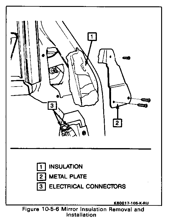
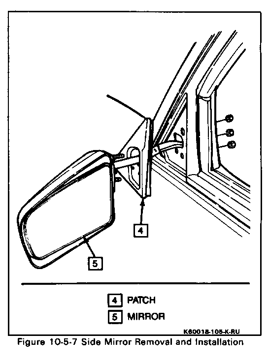
REAR VIEW EXTERIOR MIRROR (Figures 10-5-6 and 10-5- 7) ----------------------------
Remove or Disconnect
1. Front door trim panel (see procedure).
2. Peel back plastic and open electrical connector box.
3. Two mirror electrical connectors (3).
4. Three screws at metal plate (2).
5. Sound insulation (1).
6. Three nuts securing outside miffor (5) using a 10mm socket. Hold mirror to prevent damage to door paint.
7. Outside miffor assembly (5) and patch (4).
Install or Connect
1. Position outside miffor (5) and patch (4) and secure with three nuts.
2. Position sound insulation (1) and metal plate (2) and secure with three screws.
3. Two miffor electrical connectors (3) and close connector box.
4. Reposition plastic.
5. Front door trim panel (see procedure).
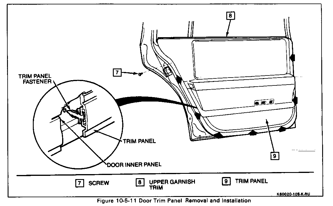
REAR DOOR TRIM PANEL (Figures 10-5-8 thru 10-5-11) -----------------------------
Remove or Disconnect
1. Negative battery cable.
2. Both pull strap covers (1). Use two small screwdrivers and carefully pry and slide off as shown.
3. Two screws at pull strap.
4. Plug (4), screw and pull control blockout cover (3).
5. Pull strap panel (2). Unplug connector at lock switch.
Removal and Installation
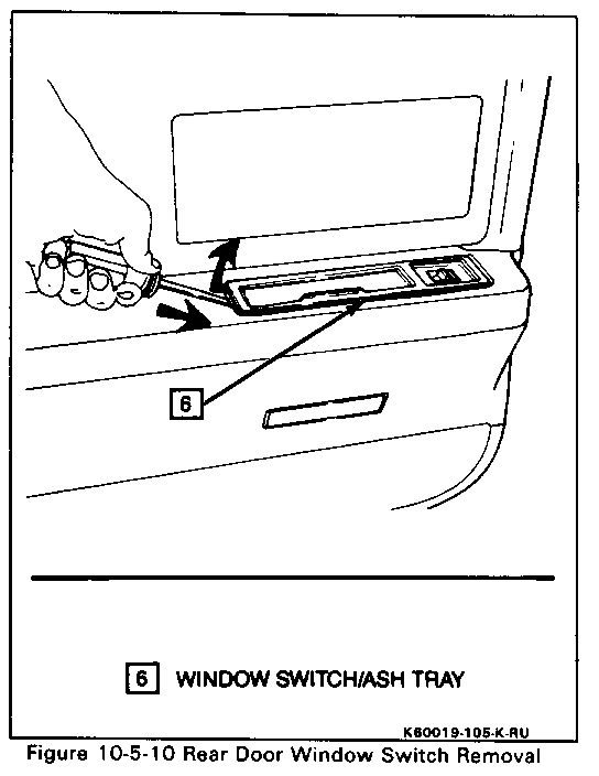
6. Window switch/ash tray (6). Using a screwdriver, carefully push in and pull up as shown. Disconnect electrical connectors at window switch (unscrew knob) and lighter.
7. Screw (7) at rear of trim panel (9).
8. Trim panel (9) using J-24595B or equivalent to disengage fasteners on trim panel from holes in door. Disconnect courtesy lamp electrical connectors.
9. Six screws and upper gamish trim (8). Removal and Installation
Install or Connect
1. Upper gamish trim (8) and secure with six screws.
2. Courtesy lamp and waming lamp electrical connectors to trim panel.
3. Trim panel (9). Align fasteners to holes in door and push in on trim panel (9).
4. Electrical connector to window switch (6) and secure with knob.
5. Electrical connector to lighter.
6. Window switch/ash tray (6). Engage tab and push down to secure.
7. Electrical connector to lock switch on pull strap panel (2).
8. Pull strap panel (2).
9. Pull control blockout cover (3), screw and plug (4).
10. Two screws at pull strap.
11. Both pull strap covers (1). Slide and snap into place.
12. Screw (7) at rear of trim panel (9).
13. Negative battery cable.
SECTION 10-7 BODY REAR END ------------- CONTENTS
Rear Compartment Lid Lock Cover Removal and Installation .................................. 10-7-1 Rear Compartment Lid Carpeting Removal and Installation .................................. 10-7-1 License Plate Pocket - Rear Removal and Installation........................................... 10-7-2 Combination Lamp Removal and Installation .............................................. 10-7-2
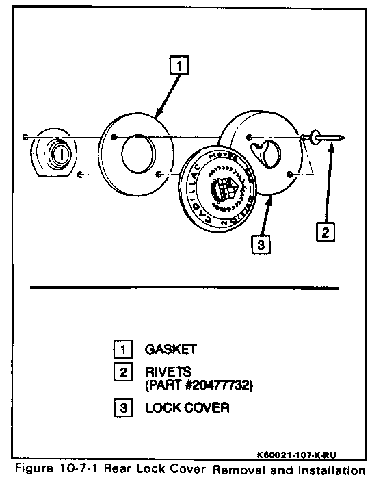
REAR COMPARTMENT LID LOCK COVER (Figure 10-7-1) ---------------
Remove or Disconnect
1. Slide lock cover exposing rivets (2).
2. Drill out rivets (2).
3. Lock cover (3) and gasket (1).
4. Rivets (2) from holes in rear compartment lid.
Install or Connect
1. Position gasket (1) and lock cover (3) over lock.
2. Secure using two rivets (2).
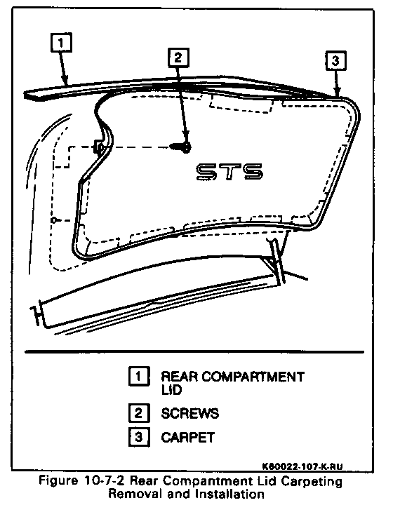
REAR COMPARTMENT LID CARPETING (Figure 10-7-2) ---------------
Remove or Disconnect
1. Open rear compartment lid (1) and peel back edge of carpet (3).
2. 10 screws (2).
3. Carpet (3).
Install or Connect
1. Position carpet (3) to rear compartment lid (1).
2. Secure with 10 screws (2).
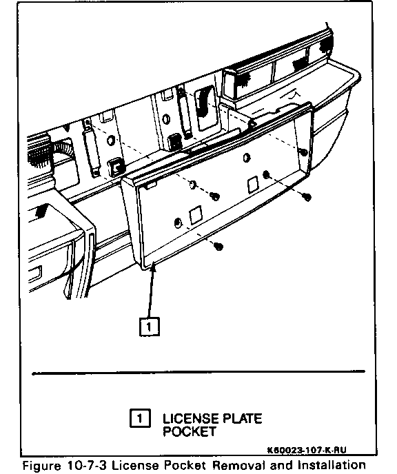
LICENSE PLATE POCKET-REAR (Figure 10-7-3) ---------------
Remove or Disconnect
1. Four screws securing license plate.
2. License plate.
3. Four screws securing license plate pocket (1).
4. License plate pocket (1).
Install or Connect
1. License plate pocket (1) and secure with four screws.
2. License plate and secure with four screws.
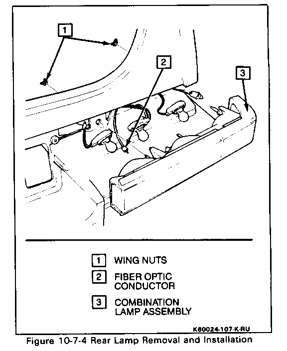
COMBINATION LAMP (Figure 10-74) --------------
Remove or Disconnect
1. Negative battery cable.
2. Open rear compartment lid and remove two plastic screws and fold back carpet exposing combination lamp wing nuts (1).
3. Two plastic wing nuts (1). 4. Combination lamp (3).
5. Turn signal, brake and reverse lamp sockets from combination lamp assembly (3). Push in tab and turn counter clockwise.
6. Side marker socket. Twist counter clockwise and pull out of combination lamp assembly.
7. Fiber optic conductor (2) from combination lamp assembly (3).
Install or Connect
1. Fiber optic conductor (2) into combination lamp assembly (3).
2. Side marker socket into combination lamp assembly (3). Push in and twist clockwise.
3. Turn signal, brake and reverse lamp sockets into combination lamp assembly (3). Push in and twist clockwise.
4. Combination lamp assembly (3) to vehicle and secure using two plastic wing nuts (1).
5. Position carpet and secure with two plastic screws.
6. Negative battery cable.
SECTION 10-9 SEATS ----- CONTENTS
Front Seat (AN3) Removal and Installation.............................................. 10-9-1 Front Seat Disassembly and Assembly ........................ 10-9-1 Rear Console Removal and Installation...................... 10-9-5
Rear Seat Lower Cushion Removal and Installation................................................ 10-9-7 Rear Seat Back Removal and Installation............................................ 10-9-7
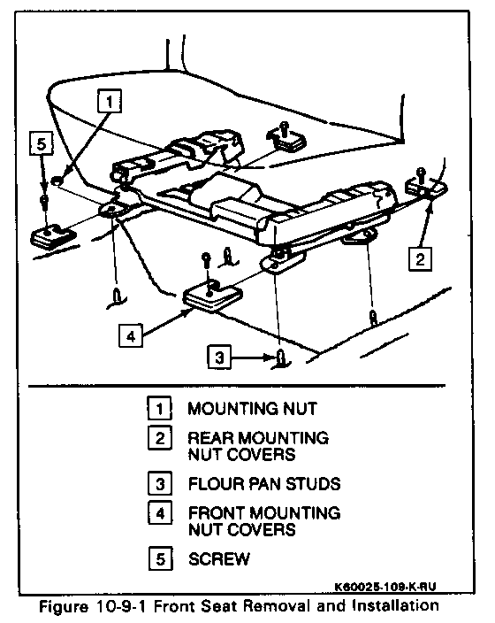
FRONT SEAT (AN3) (Figure 10-9-1) --------------- Remove or Disconnect --------------------
1. Power seat all the way back exposing two front mounting nut covers (4).
2. Both screws (5) and mounting nut covers (4).
3. Both mounting nuts (1) using a 13mm socket.
4. Power seat forward all the way exposing rear mounting nut covers (2).
5. Both screws and mounting nut covers (2).
6. Both mounting nuts using a 13mm universal socket.
7. Power seat all the way up. This will aid in disassembly.
8. Negative battery cable.
9. Pull seat up and lean back exposing electrical connectors.
10. Three electrical connectors and one air hose.
11. Front seat.
Install or Connect
1. Position front seat and lean back.
2. Three electrical connectors and one air hose.
3. Position front seat over studs in floor pan (3) and install two rear nuts using a 13mm universal socket.
4. Both mounting nut covers (2) and secure with two screws.
5. Negative battery cable.
6. Power seat all the way back, exposing front mounting studs (3).
7. Both mounting nuts (1) onto studs (3) using a 13mm socket.
8. Both mounting nut covers (4) and secure with two screws (5).
FRONT SEAT DISASSEMBLY
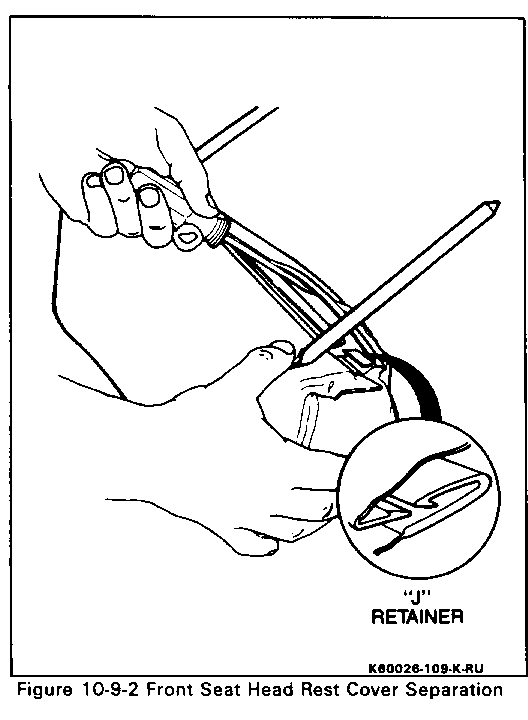
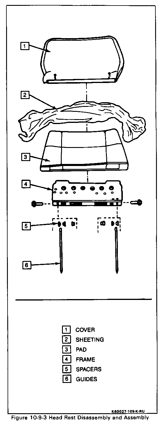
Head Rest (Figures 10-9-2 and 10-9-3) ---------------------------
Remove or Disconnect
1. Pull head rest up and articulate forward to access cover seam.
2. Seperate "J" retainers using a screw driver.
3. Head rest cover (1) and sheeting (2).
4. Pull pad (3) up exposing bolts and nuts securing guides (6) to frame (4).
5. Two nuts, bolts and four spacers (5) using a 13mm socket and 13mm wrench.
6. Pad (3) and frame (4) from guides (6).
7. Both guides (6) by rotating 180 degrees and pulling straight up.
Install or Connect
1. Position four spacers (5) and two guides (6) into head rest frame (4) and secure with two bolts and nuts.
2. Sheeting (2) over pad (3).
3. Cover (1) over pad (3) and secure "J" retainers as shown.
4. Position head rest guides (6) and slide into seat back.
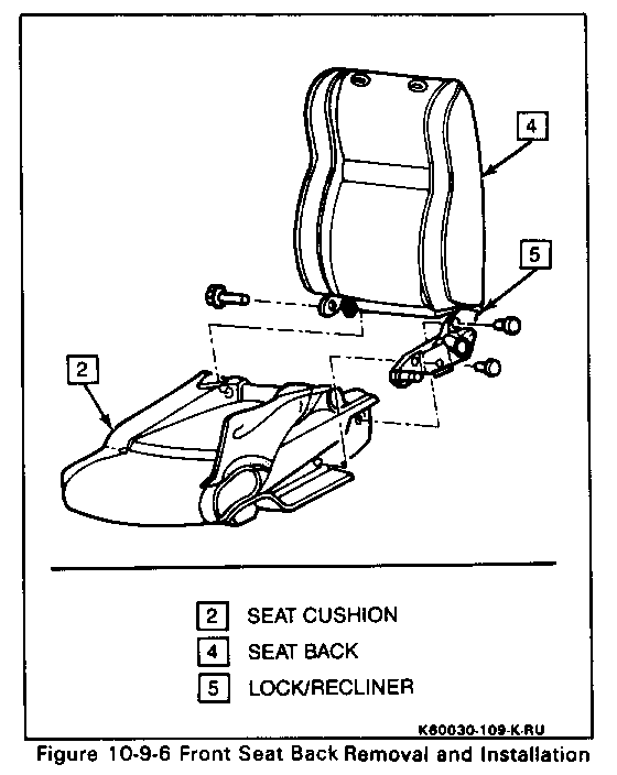
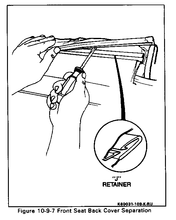
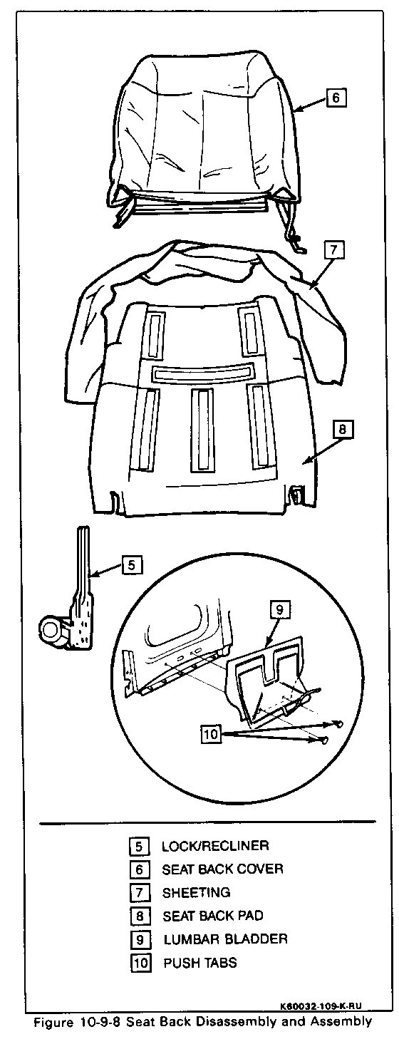
Seat Back (Figures 10-94 thru 10-9-8) ---------------------------
NOTICE: Contour bladders are serviced with the seat back cover as an assembly. However, lumbar bladder can be serviced separately.
Remove or Disconnect
1. Front seat (see procedure)
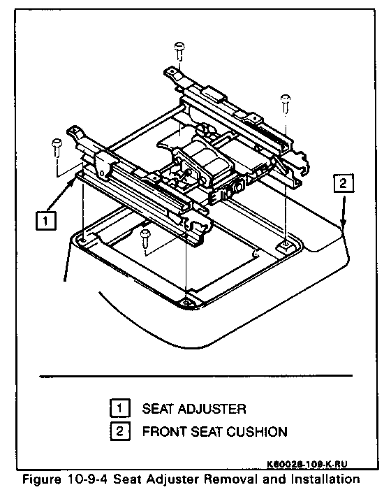
2. Four bolts and seat adjusters (1).
3. Head rest (see procedure).
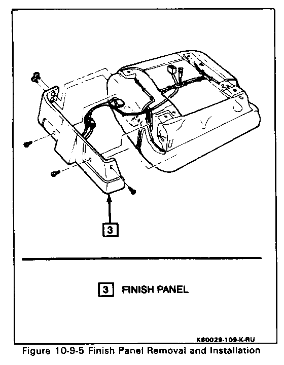
4. Five screws and finish panel (3) Disconnect electrical connectors.
5. Necessary hog rings to expose two bolts securing lock/recliner (5) to seat cushion (2). Mark location of hog rings for reassembly.
6. Three bolts securing seat cushion (2) to seat back (4).
7. "J" retainer at bottom of seat back cover (6) using a screw driver.
8. Mark the location and color of hoses and remove hoses from the three bladders in the seat back (4).
9. Seat back cover (6). Peel cover off of seat back, tuming cover inside out and seperating velcro.
10. Sheeting (7).
11. Two push tabs (10) and lumbar bladder (9).
12. Two bolts and lock recliner (5). Disconnect electrical connector.
Install or Connect
1. Position lock/recliner (5) aligning two holes in seat back (4) and secure with two bolts.
2. Position lumbar bladder (9) and secure with two push tabs (10).
3. Sheeting (7) and seat back cover (6).
4. Three hoses to three bladders noticing location marked during removal.
5. "J" retainer at bottom of seat back cover (6).
6. Position seat back (4) to seat cushion (2) aligning three boltholes.
7. Three bolts securing seat back (4) to seat cushion (2).
8. New hog rings noting the locations marked during removal.
9. Connect electrical connectors to switches in finish panel (3), position panel and secure with five screws.
10. Head rest (see procedure).
11. Seat adjuster (1) and four bolts.
12. Front seats (see procedure).
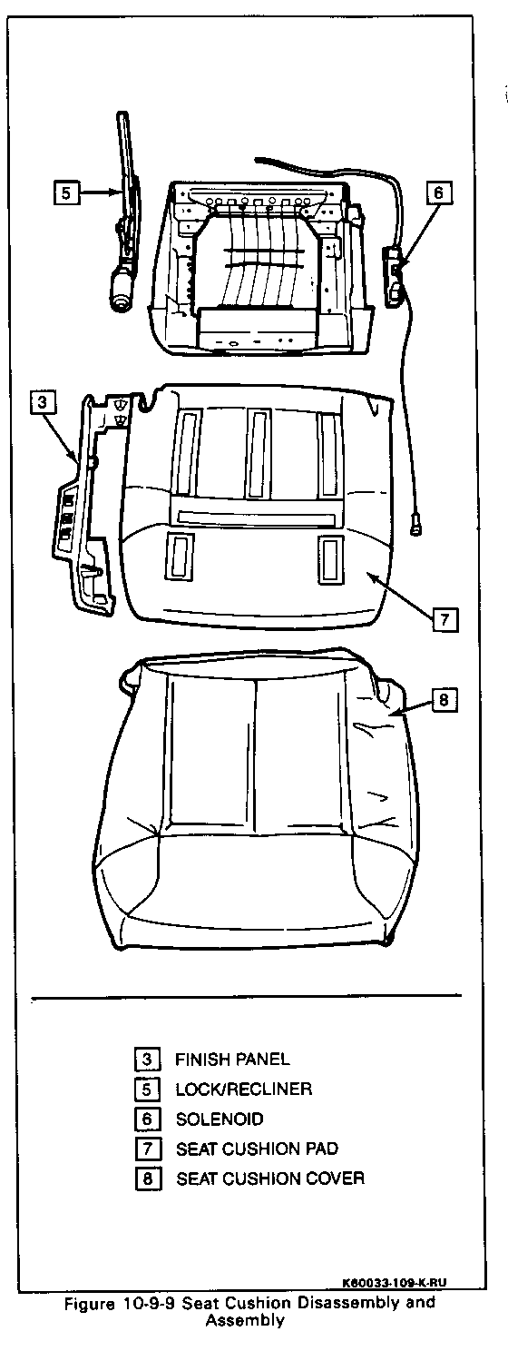
Seat Cushion (Figures 10-9-4,10-9-5,10-9-6,10-9-9) -------------------------------------
Remove or Disconnect
1. Front Seat (see procedure).
2. Front bolts and seat adjusters (1).
3. Five screws and finish panel (3). Disconnect electrical connectors.
4. All hog rings. Mark location of hog rings for ease of installation.
5. Safety belt loop, screw and push pin.
6. Peel back seat cushion cover (8) to expose two bolts securing lock/recliner (5) to seat cushion
7. Three bolts securing seat cushion (2) to seat back (4).
8. Three hoses and electrical connector at solenoid assembly (6). Mark location and color for reassembly.
9. Seat cushion cover (8).
10. Two screws and solenoid assembly (6).
Install or Connect
1. Position solenoid assembly (6) and secure with two screws.
2. Position seat cushion cover (8).
3. Three hoses and electrical connector at solenoid assembly (6) noting location marked during disassembly.
4. Position seat cushion (2) to seat back (4) aligning holes and install three bolts.
5. Safety belt loop, screw and push pin.
6. Secure seat cushion cover (8) with new hog rings at locations marked during disassembly.
7. Electrical connectors to switches on finish panel (3).
8. Position finish panel (3) and secure with five screws.
9. Front seat adjuster (1) and secure with four bolts.
10. Front seat (see procedure).
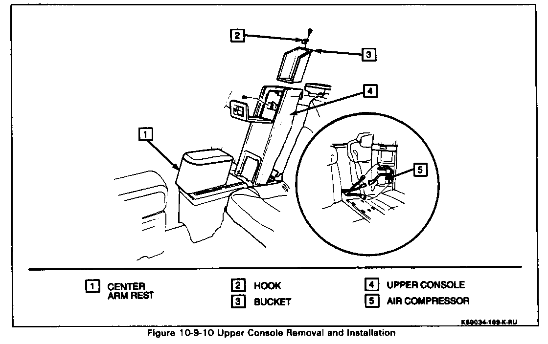
REAR CONSOLE - UPPER (Figure 10-9-10)
Remove or Disconnect
1. Center arm rest (1). Pull forward and up.
2. Eight screws, hook (2) and bucket (3) from upper console (4). Use fiber trim stick J-28628-4 to help pull up and out.
3. Two screws securing top of upper console (4) to vehicle.
4. Upper console (4) up and away far enough to access connectors.
5. Two electrical connectors and air hose at air compressor (5).
6. Upper console (4).
Install or Connect
1. Position upper console (4) close enough to install connectors.
2. Two electrical connectors and air hose at air compressor (5).
3. Position upper console (4) locating tabs into slots at bottom.
4. Two screws securing top of upper console (4) to vehicle.
5. Bucket (3) and hook (2) to upper console (4) using eight screws. Adjust hook so door closes properly.
6. Center arm rest (1). Push down and back.
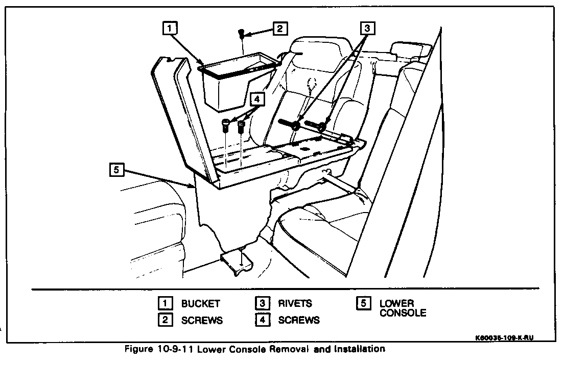
REAR CONSOLE - LOWER (Figure 10-9-11) ----------------
Remove or Disconnect
1. Upper console (see procedure).
2. Four screws (2) and bucket (1) from lower console (5). Use fiber trim stick J 28628-4, to lift up and out.
3. Two screws (4) securing lower console (5) to bracket on floor pan.
4. Two pop rivets (3) securing back of lower console (5) to vehicle. Drill out rivets (3) using a 3.5mm (9/64 in.) drill with a stop.
5. Lower console (5).
Install or Connect
1. Position lower console (5).
2. Lower console (5) to bracket on floor with two screws (4).
3. Rear of lower console (5) to vehicle using two 1/8 in. x 1/2 in. rivets (3).
4. Bucket (1) to lower console (5) with four screws (2).
5. Upper console (see procedure) and Installation
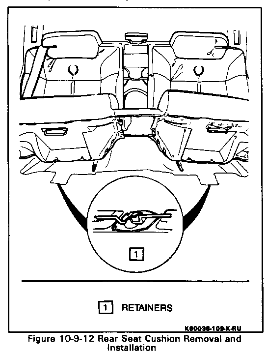
REAR SEAT LOWER CUSHION (Figure 10-9-12) ----------------
Remove or Disconnect
1. Upper console (see procedure)
2. Lower console (see procedure)
3. Push lower forward edge of seat cushion rearward, lift up and out.
Install or Connect
1. Position seat cushion, push rearward and down engaging seat cushion frame wires into retainers (1) on floor pan.
2. Lower console (see procedure).
3. Upper console (see procedure).
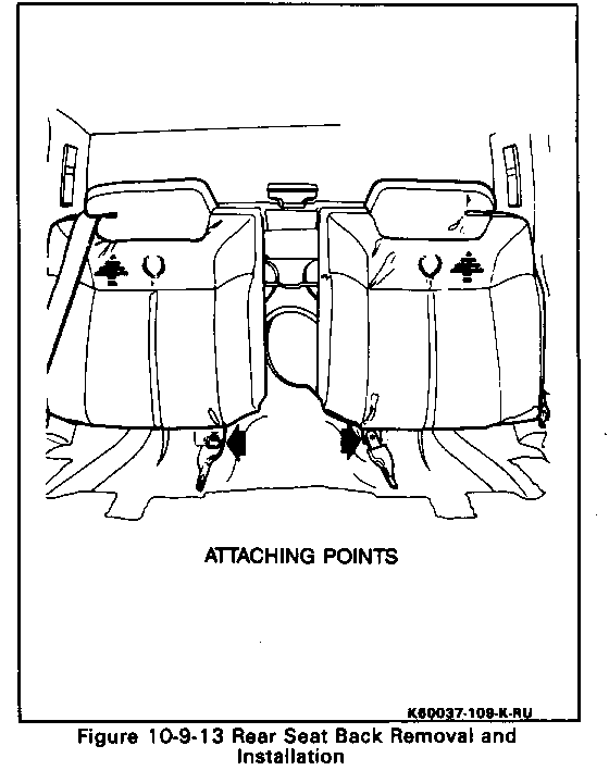
REAR SEAT BACK (Figure 10-9-13) ----------------
Remove or Disconnect
1. Upper console (see procedure).
2. Lower console (see procedure).
3. Lower seat cushion (see procedure).
4. Two lock nuts and safety belt buckles using an 18mm deepwell socket.
5. Open rear compartment lid and pull back carpet exposing seat back nuts.
6. Two nuts securing seat back using an 11mm deepwell socket.
7. Seat back.
Install or Connect
1. Position seat back.
2. Both safety belt buckles and secure with two new lock nuts using an 18mm deepwell socket.
Tighten
- Torque safety belt lock nuts to 25-45 Nm (18-33 lbs.ft.).
3. Open rear compartment lid and install two nuts securing seat back to vehicle.
Tighten
- Torque nuts to 9-12 Nm (7-8 lbs.ft.)
4. Lower seat cushion (see procedure).
5. Lower console (see procedure).
6. Upper console (see procedure).

General Motors bulletins are intended for use by professional technicians, not a "do-it-yourselfer". They are written to inform those technicians of conditions that may occur on some vehicles, or to provide information that could assist in the proper service of a vehicle. Properly trained technicians have the equipment, tools, safety instructions and know-how to do a job properly and safely. If a condition is described, do not assume that the bulletin applies to your vehicle, or that your vehicle will have that condition. See a General Motors dealer servicing your brand of General Motors vehicle for information on whether your vehicle may benefit from the information.
