- Install all eight spark plugs.
- Lock the flywheel to prevent crankshaft rotation.
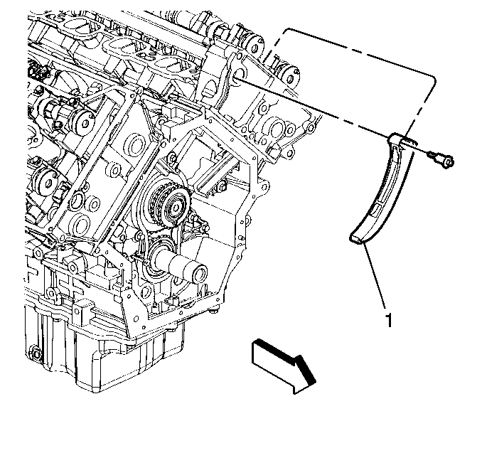
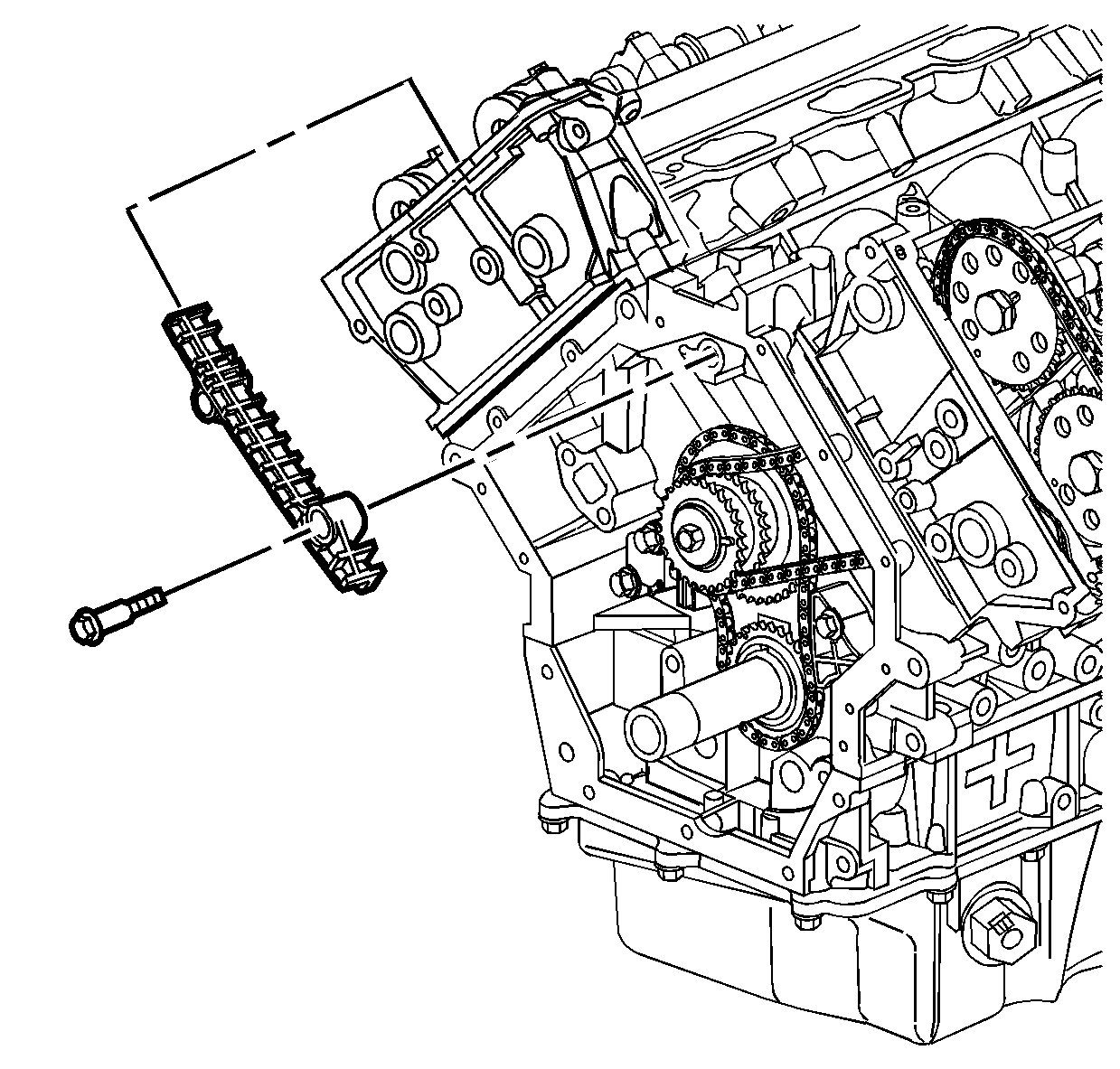
- Install the left timing chain tensioner shoe (1) and retaining bolt.
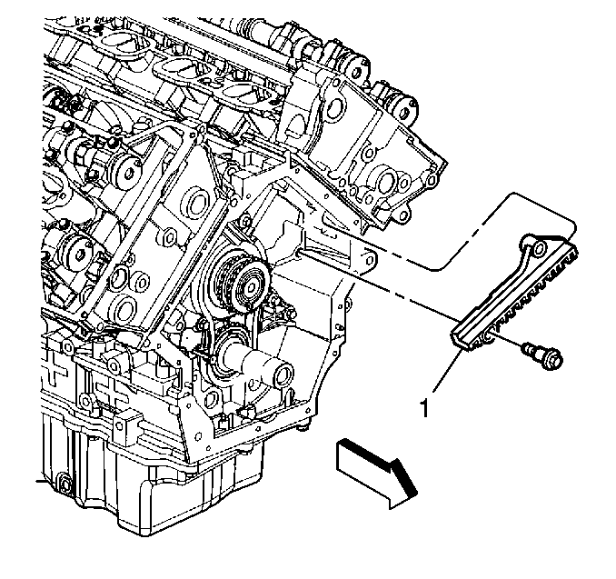
- Install the left timing chain guide (1) and lower retaining bolt.
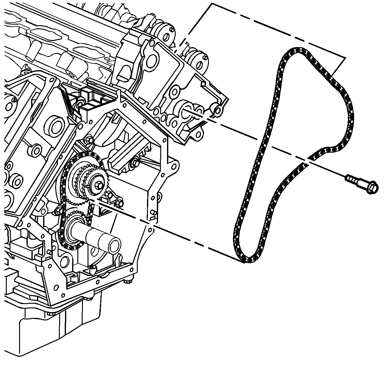
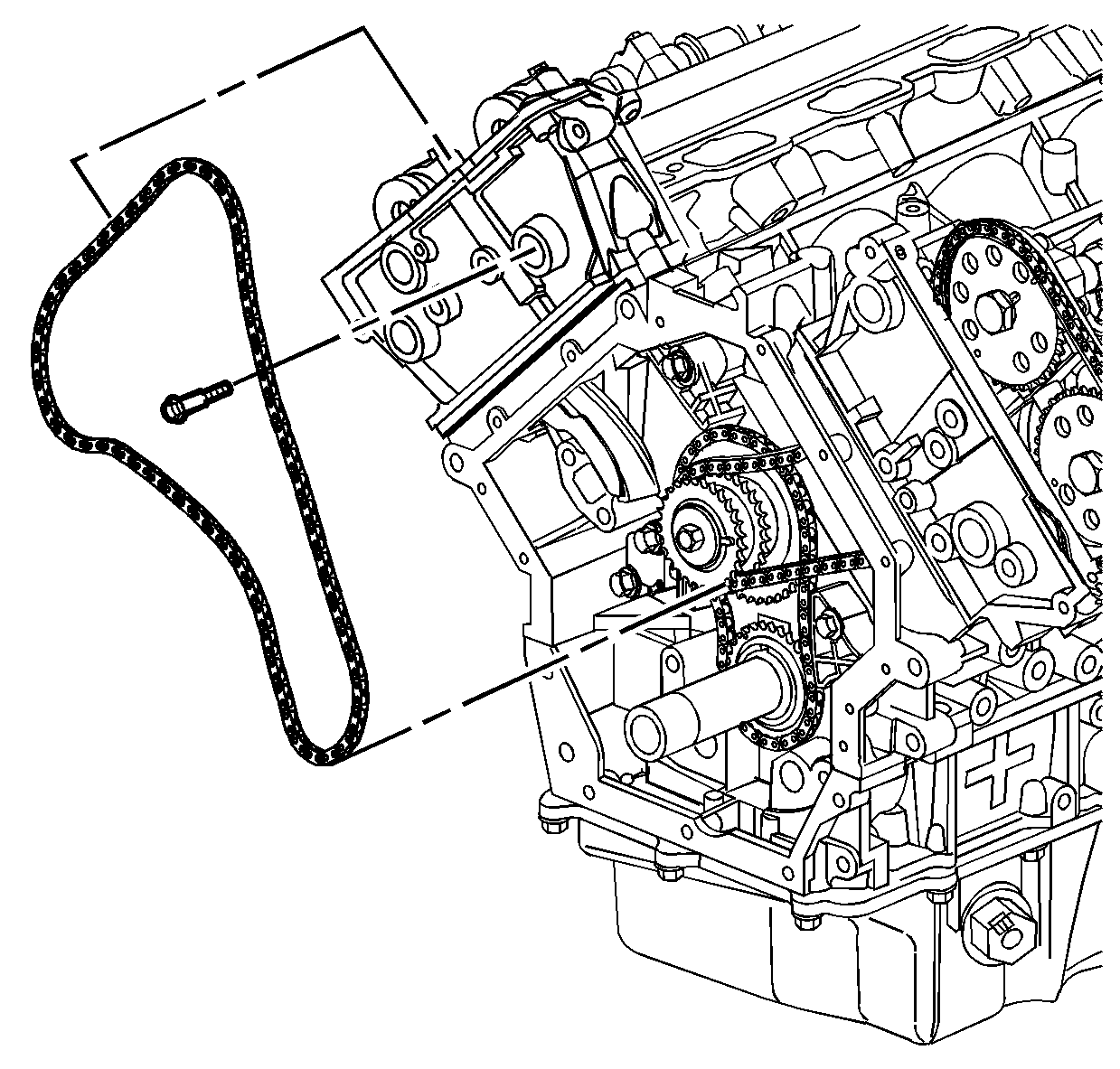
- Install the left timing chain by feeding the chain down through the cylinder head and hanging the chain on the camshafts.
- Route the left timing chain over the inner row of the intermediate sprocket teeth.
- Install the left guide upper retaining bolt through the cylinder head access hole.
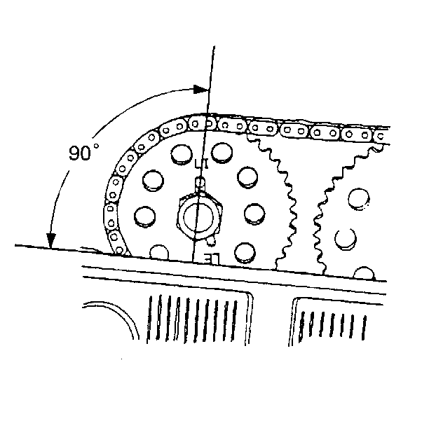
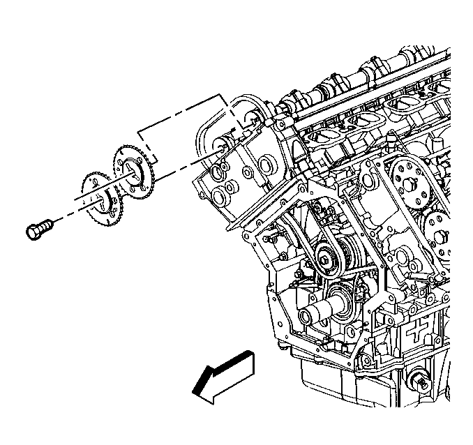
- Install the intake and exhaust camshaft sprockets into the chain and onto the camshafts so that the sprocket notch marked LI (left head intake) engages the intake cam drive pin and the sprocket notch marked LE (left head exhaust) engages the exhaust cam drive pin.
- Loosely install the intake and exhaust camshaft sprocket retaining bolts.
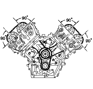
- Check the sprocket drive pin, it must be perpendicular to the head face.
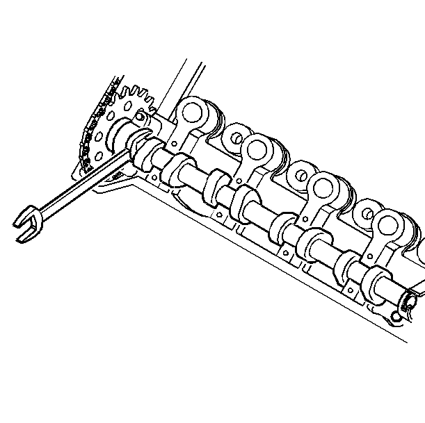
- Use the hex cast into the camshafts in front of the first set of lobes to reposition the camshafts if necessary.
- Install the right timing chain guide and lower retaining bolt.
- Install the right timing chain by feeding the chain down through the cylinder head and hanging the chain on the camshafts.
- Route the right timing chain over the outer row of intermediate sprocket teeth.
- Install the right chain guide upper retaining bolt through the cylinder head access hole.
- Install the intake and exhaust camshaft sprockets into the chain and onto the camshafts so that the sprocket notch marked RI (right head intake) engages the intake cam drive pin and the sprocket notch marked RE (right head exhaust) engages the exhaust cam drive pin. The cam drive pin must be perpendicular to the head face. A hex is cast into the camshafts in front of the lobes for cylinder 1 so that an open end wrench may be used in order to provide minor repositioning of the cams.
- Loosely install the intake and exhaust camshaft sprocket retaining bolts.
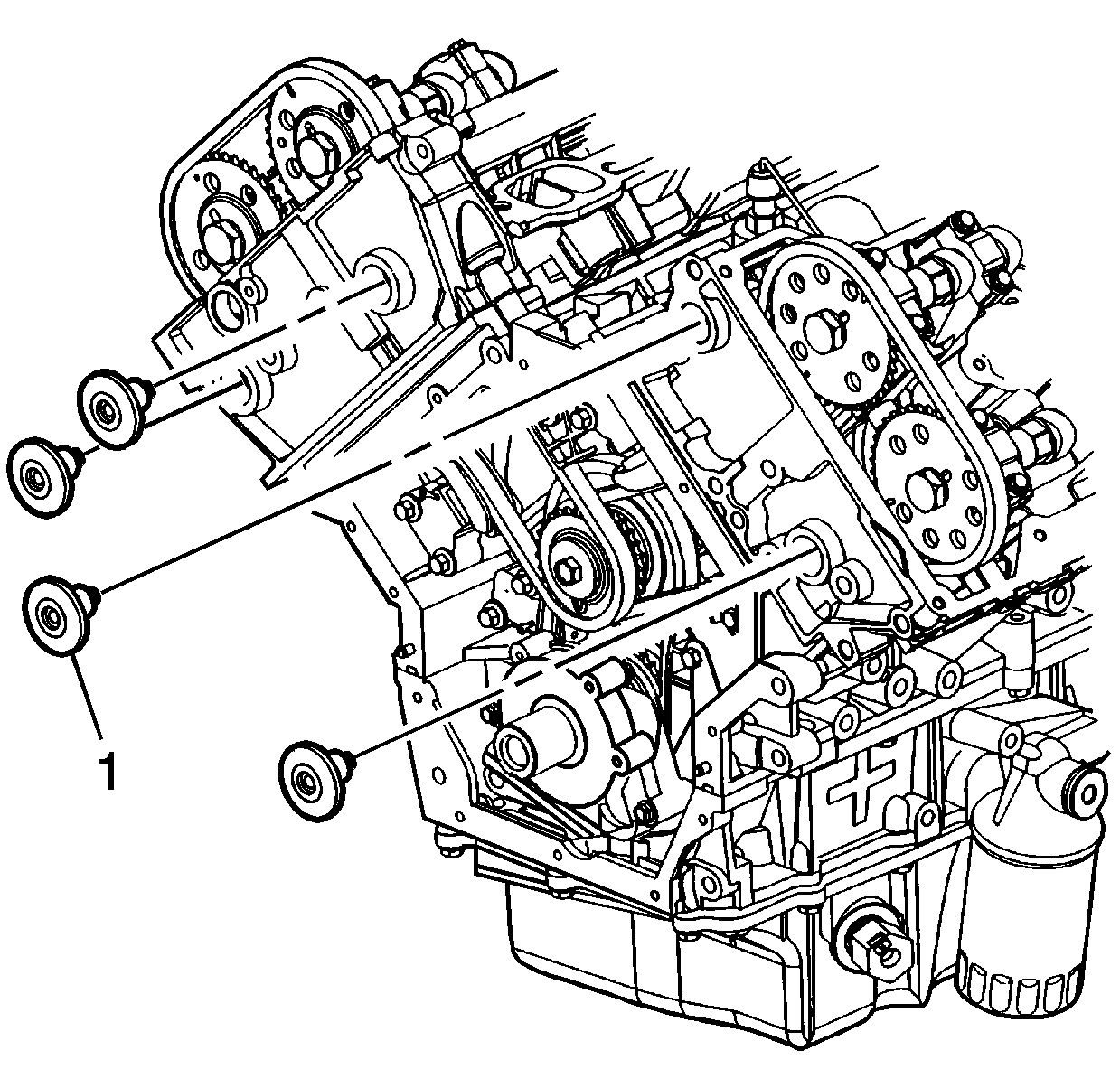
- Install the timing chain guide access plugs (1) in the front of the cylinder heads.
- Collapse the secondary drive chain tensioners using the following procedure:
- As the ratchet lever moves to its first click, hold the tensioner shoe inward and insert a pin through the hole in the release lever. The locked ratchet mechanism should hold the shoe in a collapsed position.
- Install the left timing chain tensioner and retaining bolts.
- Install the right timing chain tensioner and retaining bolts.
- Tighten the camshaft sprocket bolts. Use the hex cast into each camshaft to prevent engine rotation and provide leverage.
- Install the camshaft position sensor (1) and retaining bolt.
- Check all timing marks to make sure they are in proper position for base engine timing.
- When proper timing is assured, remove all pins from the timing chain tensioner release levers allowing the tensioner to expand and remove any slack in the timing chains.
- Check for proper base engine timing.
Notice: Use the correct fastener in the correct location. Replacement fasteners must be the correct part number for that application. Fasteners requiring replacement or fasteners requiring the use of thread locking compound or sealant are identified in the service procedure. Do not use paints, lubricants, or corrosion inhibitors on fasteners or fastener joint surfaces unless specified. These coatings affect fastener torque and joint clamping force and may damage the fastener. Use the correct tightening sequence and specifications when installing fasteners in order to avoid damage to parts and systems.
Tighten
Tighten the left timing chain tensioner shoe bolt to 25 N·m
(18 lb ft).
Tighten
Tighten the left timing chain guide bolts to 25 N·m (18 lb ft).
Tighten
Tighten the right timing chain guide bolts to 25 N·m (18 lb ft).
Tighten
Tighten the chain guide access plugs to 4.5 N·m (39 lb in).
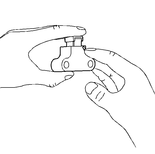
| 19.1. | Rotate the ratchet release lever counterclockwise and hold. |
| 19.2. | Collapse the tensioner shoe and hold. |
| 19.3. | Release the ratchet lever. Slowly release the pressure on the shoe. |
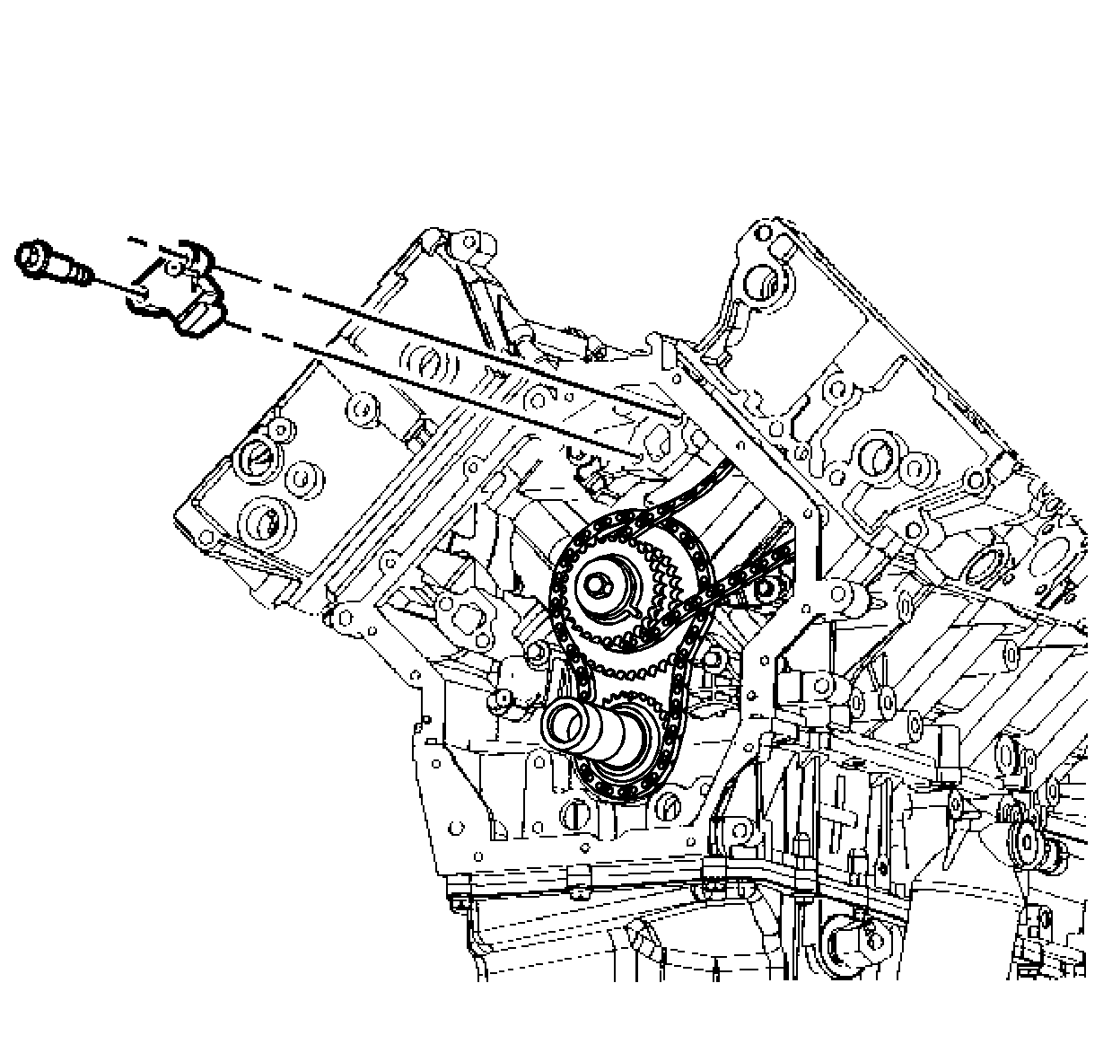
Important: Make sure the tensioner release lever faces toward you before tightening.
Tighten
Tighten the secondary drive chain tensioner bolts to 25 N·m
(18 lb ft).
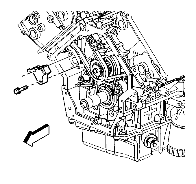
Important: Make sure the tensioner release lever faces toward you before tightening.
Tighten
Tighten the secondary drive chain tensioner bolts to 25 N·m
(18 lb ft).

Tighten
Tighten the camshaft sprocket bolts to 120 N·m (90 lb ft).
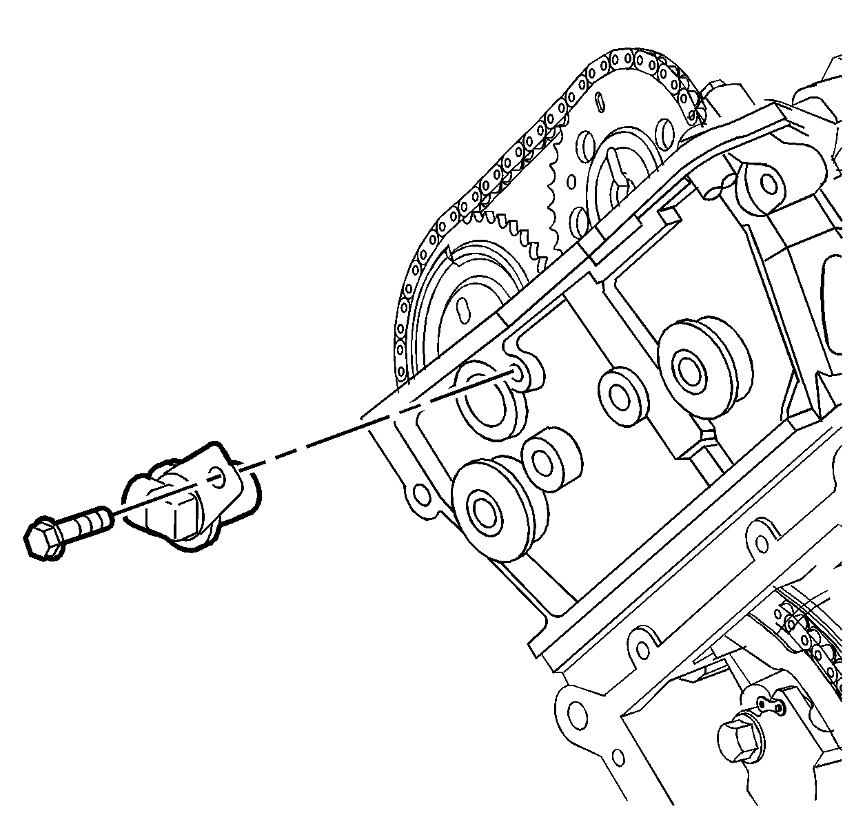
Tighten
Tighten the camshaft position sensor retaining bolt to 10 N·m
(89 lb in).
