Valve Guide Clearance
- Check the valve stem to guide clearance using a hole gage and
an outside micrometer.
- Measure the valve guide inside diameter with a hole gage, crossways
to the engine, at both the top and 10 mm (0.39 in) up from the
bottom of the guide, measuring gage each time with micrometer. A standard
size valve guide is 5.979 mm (0.235 in).
- Measure the valve stem diameter with the micrometer and subtract
from the greater of two guide measurements to obtain the maximum clearance.
- If the clearance is greater than 0.12 mm (0.0005 in)
and a new standard diameter valve stem will not bring the clearance within
specifications, the cylinder head must be replaced.
- Valve guide wear at the bottom 10 mm (0.39 in) of
the valve guide is not significant to normal operation.
Valve and Seat Grinding
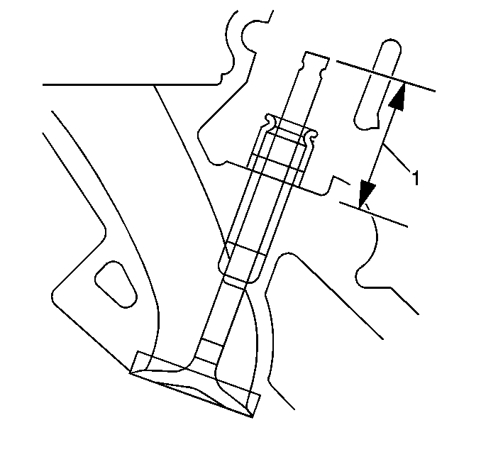
- In order to determine valve stem height, measure the distance from the valve
spring seat to the tip of the valve. The specifications for the valve stem
height are as follows:
| • | Intake valve: 35.30-36.92 mm nominal, 37.17 mm
maximum |
| • | Exhaust valve: 33.85-35.38 mm nominal, 35.63 mm
maximum |
- If the maximum length specification is exceeded, the valve or
the cylinder head must be replaced.
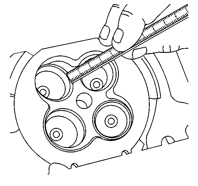
- Measure the valve seat width. The specifications for seat width are as follows:
| • | Intake valve seat width: 0.450-0.850 mm (0.017-0.033 in) |
| • | Exhaust valve seat width: 0.700-1.100 mm (0.027-0.043 |
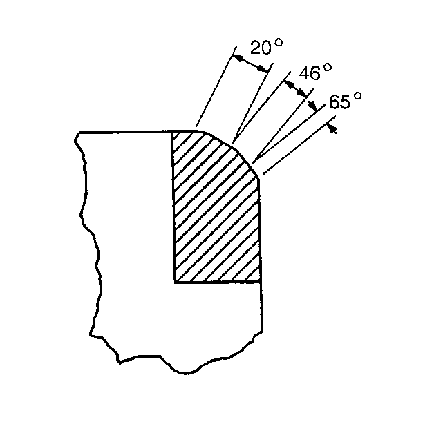
- If the valve seat width is beyond these specifications, you must grind
the seats in order to ensure proper heat dissipation and in order to prevent
the build up of carbon on the seats. Use the following procedure:
| 4.1. | Grind the valve seats with a 46° grinding stone. Use 20°
and 65° grinding stones in order to narrow the seat. |
| 4.2. | Narrow the valve seat width to 0.065 mm (0.025 in)
for the intake valve seat and 0.900 mm (0.035 in) for the exhaust
valve seat. |
| 4.3. | When grinding the valves and seats, grind off as little material
as possible. |
- If the valve seat widths are acceptable, check the valve seat
roundness.
- The roundness should be within 0.10 mm (0.004 in)
total, as measured with a dial indicator and a solid, slightly tapered pilot
which has a slight bind in the valve guide when installed.
- If the valve seats exceed the roundness specification, grind the
valve seats to within 0.05 mm (0.002 in) indicator reading when
new valves are being installed, or if the roundness, seat width, or full contact
of the valves is within specification.
- Grind the valves at a 45 degree angle.
- Install the refaced valve in the cylinder head.
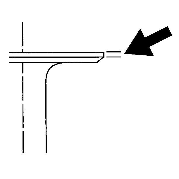
- Measure the valve margin. The specifications
for minimum valve margin are as follows:
| • | Intake valve margin: 0.127 mm (0.005 in) |
| • | Exhaust valve margin: 0.762 mm (0.030 in) |
- If the valves are below this specification, replace the valves.
- Install the valves in the cylinder head.
| 12.1. | If you are using refaced valves, lap the valves into the seats
with a fine grinding compound. The refacing and reseating operations should
leave the refinished surfaces smooth and true so that minimal lapping is required.
Excessive lapping will groove the valve face and prevent a good seat when
hot. |
| 12.2. | If you are using new valves, do not lap the valves under any condition. |
- Re-check the valve stem height. If the height is exceeded, grind
the stem to reach specifications.
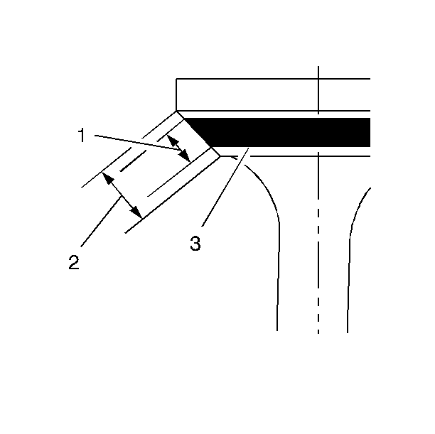
- Test the valves for seat concentricity and tight seating using the following
procedure:
| 14.1. | Coat the valve face lightly with blue dye (3). |
| 14.2. | Turn the valve against the seat. |
| 14.3. | If the valve face is concentric with the valve stem, a mark will
be made all around the face. If the face is not concentric with the stem,
a mark will be made on only one side of the face. |
| 14.4. | Coat the valve seat lightly with blue dye. |
| 14.5. | Rotate the valve against the seat to determine if the valve seat
is concentric with the valve guide and if the valve is seating all the way
around. |
| 14.6. | Both of these tests are necessary in order to prove that a proper
seat is obtained. |
Valve Spring Load Measurement
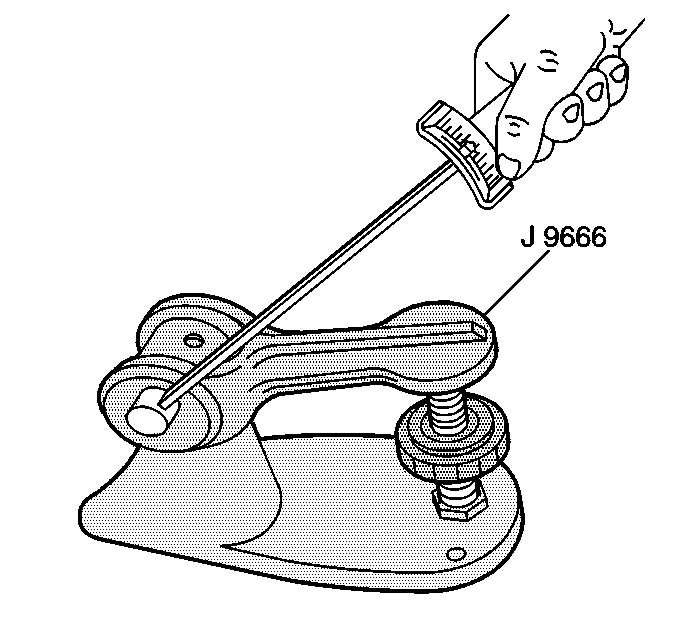
- Measure the valve spring tension. Specifications for the valve spring
tension are as follows:
RPO LD8 - VIN Y
| • | Valve Closed: 205 N (46 lb) @ 30.3 mm (1.19 in) |
| • | Valve Open: 409 N (91 lbs) @ 21.7 mm (0.854 in) |
RPO L37 - VIN 9
| • | Valve Closed: 236 N (53 lb) @ 30.3 mm (1.19 in) |
| • | Valve Open: 485 N (109 lb) @ 20.9 mm (0.823 in) |
- If low valve spring load is found, replace the valve springs.
DO NOT use shims to increase spring load. The use of shims will cause the
valve spring to bottom out before the camshaft lobe is at peak lift.


