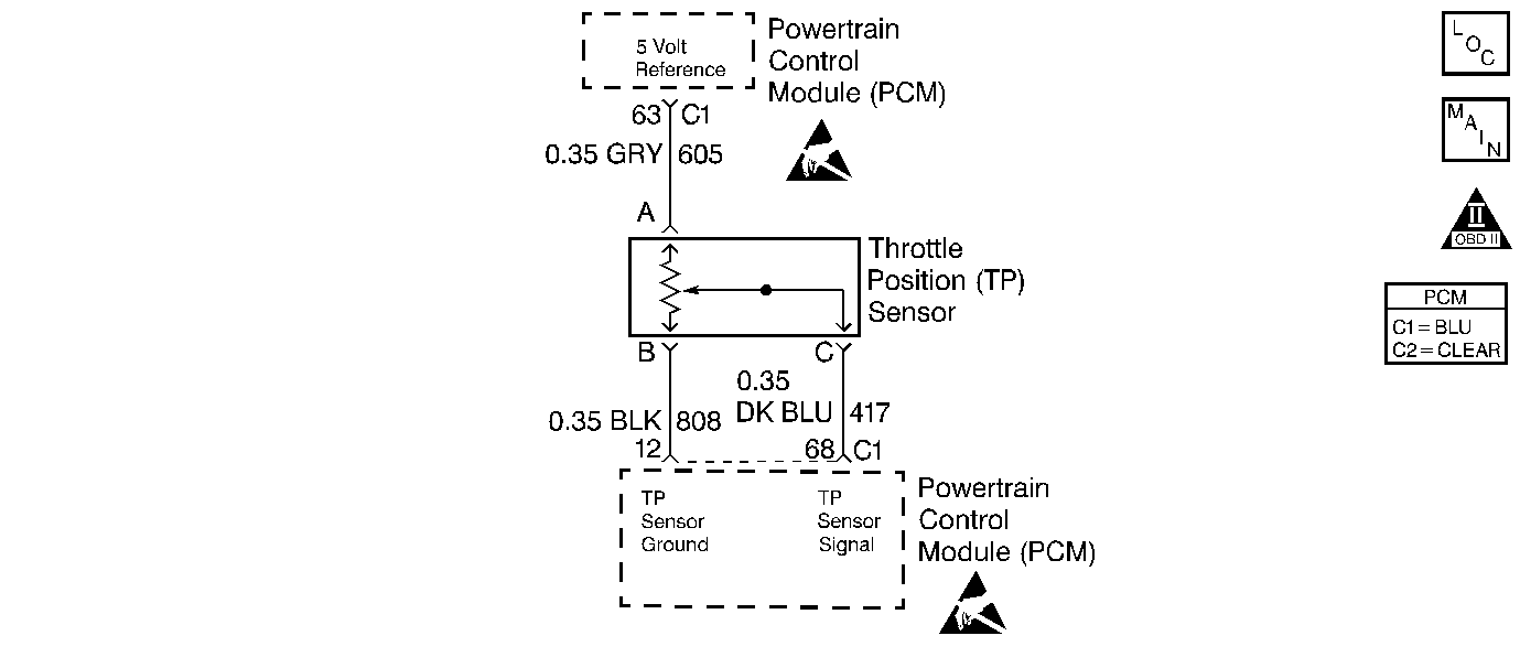
Circuit Description
The PCM learns the closed throttle position when the ignition is turned to LOCK. The closed throttle position is always corrected to 0 degrees. The correction is performed to allow for deposit buildup on the throttle valve. When the ignition is turned to LOCK, the PCM executes the TP sensor learning routine. If the same correction factor occurs on two consecutive key LOCK cycles, the TP sensor is then corrected to 0 degrees using the correction factor learned. If the value needs correction by more than 6.8 degrees, PCM DTC P1524 will be stored in memory at the next key ON cycle.
Conditions for Setting the DTC
Test Condition
TP Sensor has learned this ignition cycle.
Failure Condition
Closed throttle angle correction needed is 6.8 degrees or more.
Action Taken When the DTC Sets
| • | PCM learned TP sensor value set to 0. |
| • | The Malfunction Indicator Lamp (MIL) will not illuminate. |
| • | The PCM will command a message to be displayed. |
| • | The PCM may record operating conditions at the time the diagnostic fails. This information will be stored in the Failure Records. |
Conditions for Clearing the Message/DTC
| • | The PCM will turn the message OFF after one run and pass of the diagnostic test. |
| • | A History DTC will clear after forty consecutive warm-up cycles with no failures of any non-emission related diagnostic test. |
| • | A Last Test Failed (current) DTC will clear when the diagnostic runs and does not fail. |
| • | Use a scan tool to clear DTCs. |
| • | Interrupting PCM battery voltage may or may not clear DTCs. This practice is not recommended. Refer to Clearing Diagnostic Trouble Codes in PCM Description and Operation. |
Test Description
Number(s) below refer to the step number(s) on the Diagnostic Table.
-
Checking for TP sensor DTCs which could cause DTC P1524.
-
Checking to see if the TP sensor is out of range on the high side. TP sensor displays uncorrected TP sensor so that it can be used to check TP sensor adjustment.
-
Checking to see if the TP sensor is out of range on the low side. TP sensor displays uncorrected TP sensor so that it can be used to check TP sensor adjustment.
-
If TP sensor is within range, the throttle linkage needs to be checked for proper operation. Check that throttle and cruise cables are not binding, proper throttle return spring operation, and that throttle shaft and blades are free to move.
-
If TP sensor is within range, the throttle body bore and blades should be checked for deposits that may interfere with throttle operation.
-
If the TP sensor is out of range on the low side, either the TP sensor, a TP DTC should be set, or the throttle body is at fault.
Step | Action | Value(s) | Yes | No |
|---|---|---|---|---|
1 | Was the Powertrain On-Board Diagnostic (OBD) System Check performed? | -- | Go to A Powertrain On Board Diagnostic (OBD) System Check | |
Turn the key ON. Is DTC P0121, P0122, or P0123 set? | -- | Diagnose those DTCs first | ||
If you were sent here to perform the TP Learn Procedure Go to Step 9. Using a scan tool, with foot off accelerator, view the TP Sensor display. Is the TP sensor reading in degrees greater than the value specified? | 6.5 | |||
Is TP sensor reading in degrees less than the value specified? | -6.5 | |||
Was a repair made? | -- | |||
Was throttle body cleaning performed? | -- | |||
Is the TP sensor reading in degrees outside the range specified? | -6.5 to 6.5 | |||
8 | Replace the throttle body. Refer to Throttle Body Assembly Replacement (4.6L) . Is the repair complete? | -- | -- | |
9 |
Is the procedure complete? | -- | Go to Powertrain Control Module Diagnosis for Verify Repair | -- |
