Removal Procedure
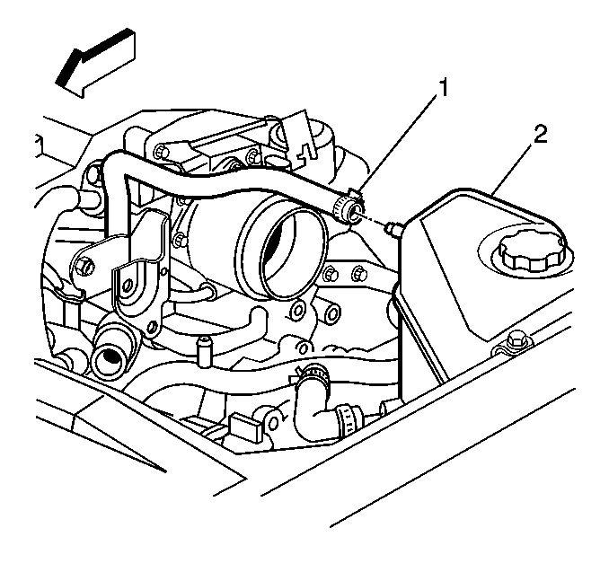
- Remove the coolant surge inlet hose (1) from the throttle body to surge tank (2) (coolant recovery tank).
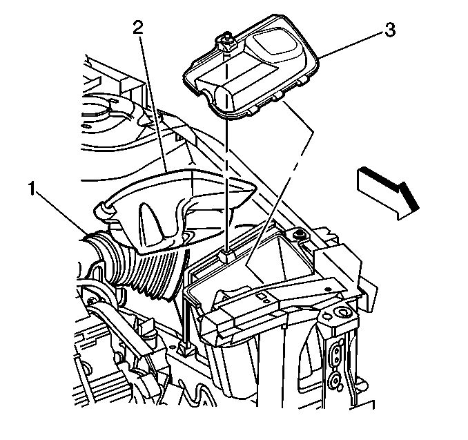
- Remove the air cleaner cover (3).
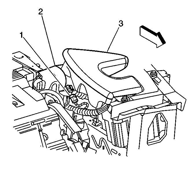
- Remove the IAT sensor connector from the IAT sensor (1).
- Loosen the intake air duct (1) clamp at the Mass Air Flow (MAF) sensor end of the duct.
- Disconnect the intake air duct (1) from the MAF sensor.
- Remove the air cleaner cover.
- Inspect the air cleaner element.
- Remove any loose debris that may be found laying in the base of the air cleaner.
- Remove the trim panel in front of the air cleaner cover to gain access to the bolts.
- Remove the bolts from the assembly.
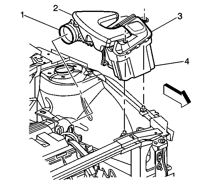
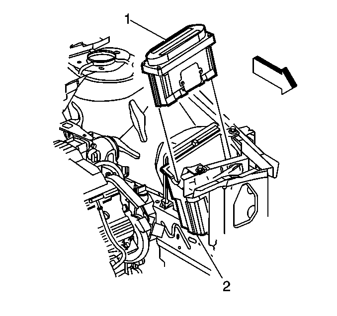
- Remove the PCM from the PCM Air Box (4).
Installation Procedure
Important: An improperly installed air cleaner or a distorted or missing intake air duct may cause at DTC to set. Ensure that the air cleaner assembly and intake air duct is installed correctly and that there are no kinks or folds in the intake air duct. Debris in the air cleaner assembly or MAF sensor inlet screen that may distort air flow can set a DTC.
- Install the PCM (1) into the air inlet housing (2).
- Install the bolts from the assembly.
- Install the trim panel in front of the air cleaner cover.
- Install a new air filter element.
- Pivot the air cleaner cover and duct assembly until the latches and cover engage in the air cleaner element base.
- Inspect to be sure that both latches latch.
- Install the intake air duct over the MAF sensor (2), being careful to ensure that the intake air duct is secure around the entire outer edge of the MAF sensor.
- Connect the IAT sensor connector (1) to the IAT sensor.
- Install the coolant surge inlet hose (1) from the throttle body to surge tank (2) (coolant recovery tank).
- Install the air cleaner cover (3).

Important: The outlet of the air cleaner assembly and the MAF sensor inlet duct must be lined up when completely installed. Misalignment may cause incorrect air flow readings resulting in MIL illumination or a driveabilty concern.
Refer to
Notice: Use the correct fastener in the correct location. Replacement fasteners must be the correct part number for that application. Fasteners requiring replacement or fasteners requiring the use of thread locking compound or sealant are identified in the service procedure. Do not use paints, lubricants, or corrosion inhibitors on fasteners or fastener joint surfaces unless specified. These coatings affect fastener torque and joint clamping force and may damage the fastener. Use the correct tightening sequence and specifications when installing fasteners in order to avoid damage to parts and systems.
in Cautions and Notices.Tighten
Tighten the clamp assembly to 3 N·m (27 lb in).


Tighten
Tighten the cover bolt to 9 N·m (80 lb in).
