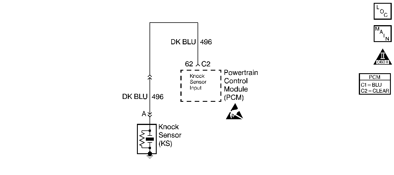
Circuit Description
During engine operation, the knock sensor will detect background noise on its circuit. The PCM monitors this noise and compares the amount of noise it monitors to the amount it expects too see. If the knock sensor system is operating correctly the background noise will generally increase as engine speed and load increase. This background noise is used to detect knock sensor circuit faults. This DTC will set if the knock sensor background noise is below an expected learned value at a given RPM and TP sensor range for a given period of time.
Conditions for Running the DTC
| • | Ignition voltage at least 10 volts. |
| • | Coolant Temperature at least 40°C (104°F). |
| • | Throttle position at least 4.8 degrees. |
| • | Engine speed at least 3000 RPM.. |
| • | Battery voltage at least 11 volts. |
Conditions for Setting the DTC
The knock sensor background noise voltage is less than 0.5 volts above the learned minimum for 1 second.
Action Taken When the DTC Sets
| • | The PCM will illuminate the malfunction indicator lamp (MIL) when the diagnostic runs and fails. |
| • | The PCM will record operating conditions at the time the diagnostic fails. This information will be stored in the Freeze Frame and Failure Records. |
Conditions for Clearing the MIL/DTC
| • | The PCM will turn the MIL OFF after three consecutive drive trips that the diagnostic runs and does not fail. |
| • | A Last Test Failed (current) DTC will clear when the diagnostic runs and does not fail. |
| • | A History DTC will clear after forty consecutive warm-up cycles with no failures of any emission related diagnostic test. |
| • | Use a scan tool to clear DTCs. |
| • | Interrupting PCM battery voltage may or may not clear DTCs. This practice is not recommended. Refer to Clearing Diagnostic Trouble Codes in PCM Description and Operation. |
Diagnostic Aids
Check for an intermittent open or short on CKT 496.
Test Description
Number(s) below refer to the step number(s) on the Diagnostic Table.
-
Checking knock sensor and knock sensor signal circuit under intake manifold.
-
Checking if circuit or sensor is at fault.
-
Checking knock sensor signal circuit to PCM.
-
Checking if PCM is faulty or fault is not present.
Step | Action | Value(s) | Yes | No |
|---|---|---|---|---|
1 | Did you perform the Powertrain On-Board Diagnostic (OBD) System Check? | -- | ||
Does frequency fluctuate while tapping on block? | -- | |||
Does frequency fluctuate while tapping on block? | -- | |||
4 | Repair open or short to ground in knock sensor signal circuit between knock sensor and knock sensor / starter solenoid connector. Is the repair complete? | -- | Go to Powertrain Control Module Diagnosis for Verify Repair | -- |
Does frequency fluctuate while tapping on block? | -- | |||
Repair open or short to ground in knock sensor signal circuit between PCM connector C2 and knock sensor / starter solenoid connector terminal B. Is the repair complete? | -- | Go to Powertrain Control Module Diagnosis for Verify Repair | -- | |
7 |
Did the DTC reset? | -- | Fault not present. Refer to Diagnostic Aids | |
8 |
Was terminal contact repaired? | -- | Go to Powertrain Control Module Diagnosis for Verify Repair | |
9 |
Was terminal contact repaired? | -- | Go to Powertrain Control Module Diagnosis for Verify Repair | |
10 | Replace the knock sensor. Refer to Knock Sensor Replacement . Is the replacement complete? | -- | Go to Powertrain Control Module Diagnosis for Verify Repair | -- |
11 | Replace the PCM. Refer to Powertrain Control Module Replacement . Is the replacement complete? | -- | Go to Powertrain Control Module Diagnosis for Verify Repair | -- |
