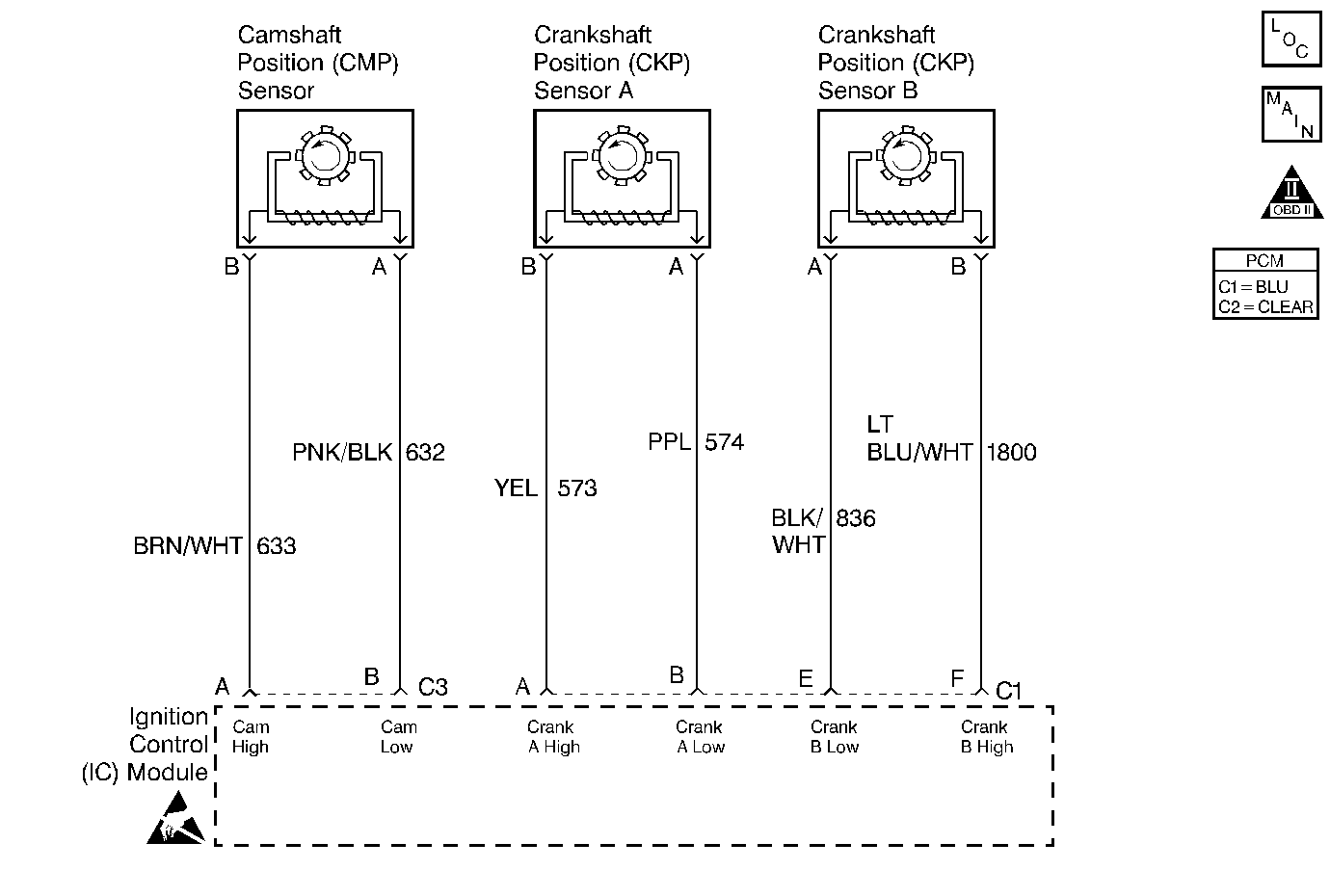
Circuit Description
The diagnostic test checks for CAM reference pulses not received when 4X reference pulses are being received. This indicates a CAM sensor circuit failure and DTC P0340 is set.
Conditions for Running the DTC
| • | DTC P0322 not set. |
| • | 4X reference pulses being received. |
| • | Engine speed 1600 RPM or less. |
Conditions for Setting the DTC
A CAM reference pulse was not received for 5.3 seconds.
Action Taken When the DTC Sets
| • | The PCM will illuminate the malfunction indicator lamp (MIL) when the diagnostic runs and fails. |
| • | The PCM will record operating conditions at the time the diagnostic fails. This information will be stored in the Freeze Frame and Failure Records. |
Conditions for Clearing the MIL/DTC
| • | The PCM will turn the MIL OFF after three consecutive drive trips that the diagnostic runs and does not fail. |
| • | A Last Test Failed (current) DTC will clear when the diagnostic runs and does not fail. |
| • | A History DTC will clear after forty consecutive warm-up cycles with no failures of any emission related diagnostic test. |
| • | Use a scan tool to clear DTCs. |
| • | Interrupting PCM battery voltage may or may not clear DTCs. This practice is not recommended. Refer to Clearing Diagnostic Trouble Codes in PCM Description and Operation. |
Test Description
Number(s) below refer to the step number(s) on the Diagnostic Table.
-
Check to see if DTC P1376 is set because a REF LO problem can cause other ignition problems.
-
Checking if the PCM is receiving CAM pulses, The scan tool will not display 4X ref counts if CAM pulses are not received
-
Checking for actual CAM pulses to the PCM.
Step | Action | Value(s) | Yes | No |
|---|---|---|---|---|
1 | Did you perform the Powertrain On-Board Diagnostic (OBD) System Check? | -- | ||
Connect a scan tool. Is DTC P1376 also set? | -- | |||
Does the disply show any counts? | -- | Fault not present. | ||
4 |
Is the voltage in the range specified? | 1 - 4 volts | ||
Is the frequency in the range specified? | 5 - 9 Hz | |||
6 | Repair circuit(s) 632 and 633 for open/short or short to voltage. Was a problem found and repaired? | -- | Go to Powertrain Control Module Diagnosis for Verify Repair | |
7 | Replace the cam sensor. Refer to Camshaft Position Sensor Replacement . Is the replacement complete? | -- | Go to Powertrain Control Module Diagnosis for Verify Repair | -- |
8 | Repair circuit 630 for a open/short or short to voltage. Was a problem found and repaired? | -- | Go to Powertrain Control Module Diagnosis for Verify Repair | |
9 | Replace the Ignition Control module. Refer to Ignition Control Module Replacement . Is the replacement complete? | -- | Go to Powertrain Control Module Diagnosis for Verify Repair | -- |
10 |
Was terminal contact repaired? | -- | Go to Powertrain Control Module Diagnosis for Verify Repair | |
11 | Replace the PCM. Refer to Powertrain Control Module Replacement . Is the replacement complete? | -- | Go to Powertrain Control Module Diagnosis for Verify Repair | -- |
