GM Service Manual Online
For 1990-2009 cars only

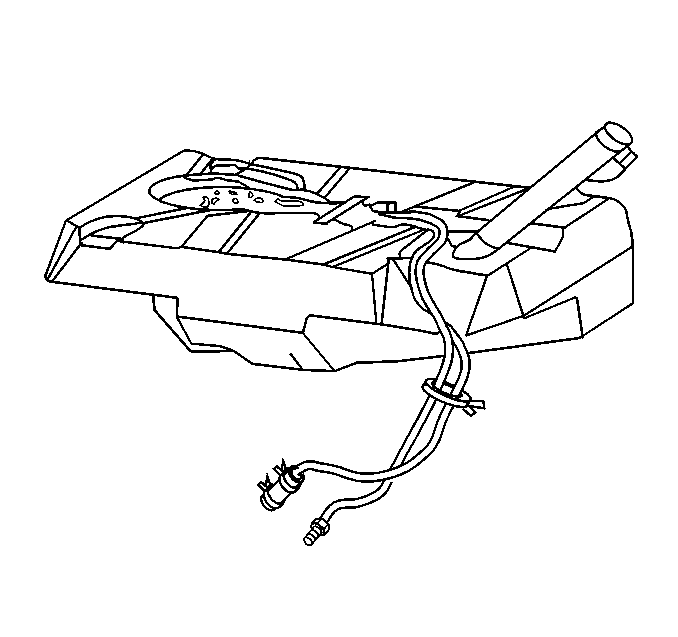
Fuel Tank


Object Number: 155114  Size: SH

The fuel storage tank is made of high density polyethylene and is located in front of the rear wheels. It is held in place by two metal straps attached to the under body of the vehicle. The tank shape includes a sump to maintain a constant supply of fuel around the fuel pump strainer during low fuel conditions or aggressive maneuvers. The tank also contains a fuel vapor vent valve with roll-over protection. The vent valve also features a two phase vent calibration which increases fuel vapor flow to the canister when operating temperatures increase the tank pressure beyond an established threshold.

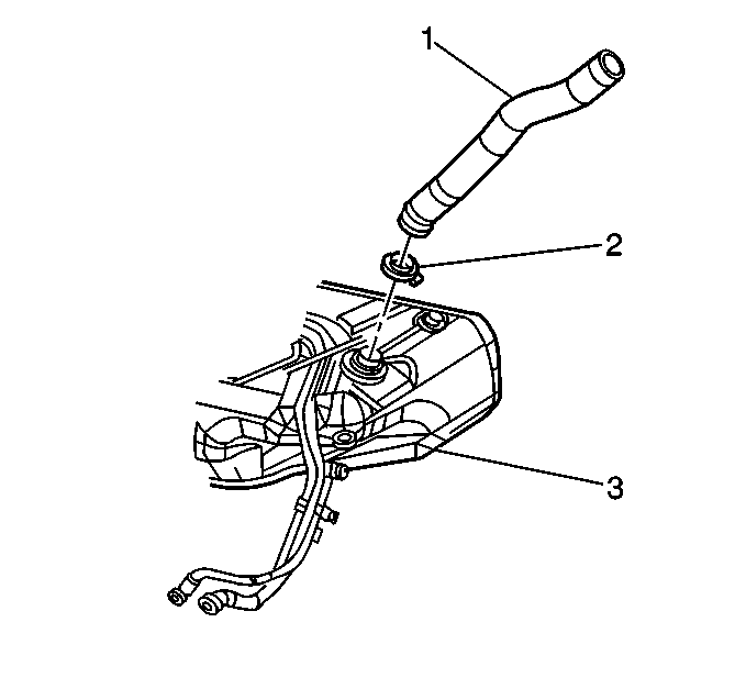
Fuel Tank Filler Pipe


Object Number: 104599  Size: SH
(1)Fuel Tank Filler Pipe
(2)Fuel Tank Filler Pipe Clamp
(3)Fuel Tank

To help prevent refueling with leaded fuel, the fuel filler pipe has a built-in restrictor and deflector. The opening in the restrictor will accept only the smaller unleaded gasoline fuel nozzle which must be fully inserted to bypass the deflector. The filler pipe is attached to the tank by a section of hose and a clamp. The tank is vented during filling by an internal vent tube inside the filler pipe.
Fuel Filler Cap


Object Number: 104597  Size: SH
(1)Fuel Tank Filler Cap
(2)Fuel Tank Filler Pipe
(3)Fuel Filler Door

The Enhanced EVAP fuel tank pipe cap has a tether connected to the fuel filler pipe door.

Notice: If a fuel tank filler pipe cap requires replacement, use only a fuel tank filler pipe cap with the same features. Failure to use the correct fuel tank filler pipe cap can result in a malfunction of the fuel system. A loose or incorrect fuel tank filler pipe cap can set a DTC.

Fuel Tank Vapor Pressure Sensor


Object Number: 18839  Size: SH

The fuel tank pressure sensor is used to detect small leaks in the evaporative emission system. The fuel tank pressure sensor is a three wire strain gauge sensor much like that of the common GM MAP sensor. However, this sensor has very different electrical characteristics due to its pressure differential design. The sensor measures the difference between the air pressure (or vacuum) in the fuel tank and the outside air pressure. The sensor mounts at the top of the fuel tank. A three wire electrical harness connects it to the Powertrain Control Module (PCM). The PCM supplies a five volt reference voltage and ground to the sensor. The sensor will return a voltage between 0.1 and 4.9 volts. When the air pressure in the fuel tank is equal to the outside air pressure, such as when the fuel fill cap is removed, the output voltage of the sensor will be 1.3 to 1.7 volts. Refer to Evaporative Emission Control System Diagnosis .

Enhanced Evaporative Emission (EVAP) Service Port


Object Number: 21046  Size: SH

The enhanced EVAP service port is located in the evaporative purge hose located between the purge solenoid and the EVAP charcoal canister. The service port is identified by a green colored cap. The port contains a schrader valve and fittings to allow the connection of the J 41413, evaporative pressure/purge diagnostic system. Refer to Evaporative Emission Control System Diagnosis for further information and diagnosis of the Enhanced EVAP system.

Modular Fuel Sender - Fuel Level Sensor

The modular fuel sender assembly mounts to the threaded opening of the plastic fuel tank with a multi-lipped seal and threaded retainer (nut). The spring loaded reservoir, containing the exterior inlet strainer, electric fuel pump and pump strainer, maintains contact with the tank bottom. This design provides:

    • Optimum fuel level in the integral fuel reservoir during all fuel tank levels and driving conditions.
    • Improved tank fuel level measuring accuracy.
    • Improved coarse straining and added pump inlet filtering.
    • More extensive internal fuel pump isolation for noiseless operation.

The modular fuel sender assembly consists of the following major components: A fuel sender cover assembly, a fuel sender, fuel pipes (above cover), a fuel sender support assembly, a fuel pump, a fuel pump strainer, a fuel pump reservoir, a fuel sender strainer, and a fuel level sensor assembly.

Modular Fuel Sender - Fuel Flow


Object Number: 570222  Size: LF
(1)Fuel Feed
(2)Fuel Return
(3)Convoluted Fuel Tube (Flex Pipe)
(4)Secondary Umbrella Valve
(5)External Fuel Pump Strainer
(6)Fuel Flow from External Strainer
(7)Fuel Pump Strainer
(8)Fuel Pump

The modular fuel sender assembly maintains optimum fuel level in the reservoir (bucket). Fuel entering the reservoir (bucket) is drawn in by:

    • The first stage of the fuel pump through the external strainer.
        And/Or
    • The secondary umbrella valve,
        Or
    • The return fuel pipe, whenever the level of fuel is below the top of the reservoir.

The fuel pump used in this system is part of the fuel sender assembly. The fuel pump lower connector assembly prevents the transmission of vibration and noise generated by the pump to the fuel tank.

Fuel enters the lower inlet port (secondary umbrella valve located inside of lower inlet port) of the electric fuel pump after being filtered by the external fuel strainer, and the fuel pump strainer. The initial function of the pump is to fill the reservoir.

The second stage separates vapor from the fuel in the pump. This vapor separation maximizes hot fuel handling and permits the vapor to return to the fuel tank at lower pressure and temperature. By creating positive fuel pressure, the pump then discharges the liquid fuel into the third stage of the pump. The pump outlet allows the fuel volume to flow through a check valve into the fuel pump flex pipe. The check valve seat is molded inside the connector body. The check valve body and retainer are assembled into the connector body. The check valve restricts fuel back flow.

After the fuel pump flex pipe, the fuel exits the assembly through the fuel feed output fitting on the molded cover. The cover also contains a fuel return provision which connects to one of three hollow support pipes.

Modular Fuel Sender Assembly


Object Number: 188361  Size: SH
  1. Fuel Tank Pressure Sensor
  2. Fuel Pipes
  3. Fuel Pump
  4. External Fuel Strainer
  5. Fuel level Sensor
  6. Cover

These quick-connect end fittings allow fuel feed and fuel return. Electrical power to the fuel pump enters the unit by way of a connector which is attached to the cover. An internal wire harness and connector assembly connects to the fuel pump and level sensor. The modular design adds additional functions that improve accuracy and ensure constant, steady fuel supply under all conditions. All components and subassemblies of the modular sender attach to a common cover and access the fuel tank through a single opening. The modular fuel sender assembly is spring loaded to the bottom of the fuel tank. This bottom referencing permits continuous fuel pickup and accurate fuel level sensing. The reservoir assembly is the lower section of the modular unit which encases the fuel pump. A retainer attaches to the top of the reservoir. Fuel is captured and maintained in reservoir at a level sufficient to submerge pump.

A rubber bumper (pad) is assembled between the bottom of the reservoir and the fuel sender strainer. This promotes noise isolation by acting as a buffer between the reservoir bottom and the fuel tank and provides a fastening mechanism for the fuel level sensor assembly to the reservoir.

Two quick-connect pipe end fittings are molded onto the cover of the modular unit for ease of unit removal from the fuel tank. These quick-connect end fittings allow fuel feed and fuel return.

The tank also contains a fuel vapor vent valve with roll-over protection. The vent valve also features a two phase vent calibration which increases fuel vapor flow to the canister when operating temperatures increase the tank pressure beyond an established threshold.

Modular Fuel Sender Serviceable Components

The serviceable components on the modular fuel sender are the fuel sender strainer, and the fuel level sensor assembly.

The strainer acts as a coarse filter to: filter contaminants, separate water from fuel, and to provide a wicking action that helps draw fuel into the fuel pump.

Fuel stoppage at the strainer indicates that the fuel tank contains an abnormal amount of sediment or water. Therefore, the fuel tank should be removed, cleaned, and the filter strainer replaced. Refer to Fuel System Cleaning .

Fuel Level Sender Assembly


Object Number: 50562  Size: SH

The fuel level sender attaches to the outside of the reservoir and measures the amount of fuel in the tank. The fuel level sender consists of the following components: the rheostat, the float, and the float arm. The assembly converts changes in the fuel level to a variable electrical signal used to drive a gauge in the instrument cluster. An electrical harness attached to the fuel sender cover connects the rheostat to the vehicle's wiring harness.

In-Line Fuel Filter (Typical)


Object Number: 12628  Size: SH
(1)Fuel Filter Housing
(2)Fuel Filter Element

A in-line filter is used in the fuel feed pipe ahead of the fuel injection system. The filter element is made of paper, and is designed to trap particles in the fuel that may damage the injection system. A plastic quick-connect type fitting is used at the inlet of the filter and a threaded fitting is used on the engine side of the filter.

Powertrain Control Module

The PCM receives data from various information sensors, determines the required fuel and idle speed values and then controls the IAC valve, eight fuel injectors, and spark advance to maintain the optimum performance and driveability under all driving conditions. For more information on the PCM, refer to Powertrain Control Module Diagnosis .

Fuel Pump Relay


Object Number: 104769  Size: SH
(1)Rear Electrical Center

The fuel pump relay is located below the rear seat inside the rear electrical center. The fuel pump relay allows the fuel pump to be energized by the PCM. When the ignition is first turned On, the PCM energizes the fuel pump relay for two seconds. This allows the fuel pump to run for two seconds and build up fuel pressure for cranking. The PCM then waits for ignition reference pulses from the Ignition Control Module (ICM). Once the PCM sees references pulses, the PCM energizes the relay to run the fuel pump.

A faulty fuel pump relay may cause long cranking times and should set a DTC.