GM Service Manual Online
For 1990-2009 cars only

Intake Manifold and Throttle Body Components


Object Number: 107048  Size: LF
(1)Cover -- Intake Manifold
(2)Wiring Harness Assembly -- Fuel Injector
(3)Cartridge Regulator Assembly -- Fuel Pressure
(4)Ring -- Back Up
(5)O-Ring -- Regulator Seal
(6)Filter -- Regulator
(7)O-Ring -- Regulator Seal
(8)Clip -- Regulator Retainer
(9)Cap -- Fuel Pressure Connection
(10)Core assembly -- Fuel Pressure
(11)O-Ring -- MFI Fuel Injector Upper
(12)Clip -- MFI Fuel Injector Retainer
(13)Injector Assembly -- MFI Fuel
(14)O-Ring -- MFI Fuel Injector Lower
(15)Rail Assembly -- Fuel
(16)Spacer -- Throttle Body
(17)Screw -- Throttle Body Spacer Attaching
(18)Gasket -- Throttle Body
(19)Body Assembly -- Throttle
(20)Screw -- Throttle Body Attaching
(21)O-Ring -- TP Sensor
(22)Sensor -- Throttle Position (TP)
(23)Screw -- TP Sensor Attaching
(24)Screw -- IAC Valve Attaching
(25)Valve Assembly -- Idle Air Control (IAC)
(26)O-Ring -- IAC Valve Assembly
(27)Bolt -- Intake Manifold Attaching
(28)Housing Assembly -- Intake Manifold
(29)Gasket -- Intake Manifold
(30)Spacer -- Intake Manifold
(31)Stud -- Intake Manifold Cover Attaching

Fuel Feed, Return, and EVAP Pipes - Engine Compartment


Object Number: 130538  Size: SH
(1)Fuel Line Retainer
(2)Fuel Return Pipe
(3)Fuel Feed Pipe
(4)Fuel Pipe Retaining Clip
(5)Fuel Purge Hose

The fuel feed pipe delivers the fuel from the fuel tank to the fuel rail assembly. The fuel feed pipe carries excess fuel from the outlet port of the fuel rail back to the fuel tank. The canister purge pipe transfers fuel vapors to the charcoal canister.

Fuel Feed, Return, EVAP Pipes, and Canister - Chassis


Object Number: 104626  Size: SH
(1)Fuel Tank Vapor Hose To EVAP Canister
(2)Vent Hose To EVAP Canister
(3)Purge Hose To EVAP Canister
(4)In-line Fuel Filter
(5)Fuel Feed Pipe
(6)Fuel Return Pipe
(7)Retainer

The fuel feed, return, vacuum and EVAP pipes are assembled as a harness. Retaining clips hold the pipes together and provide a means for attaching the pipes to the vehicle. Quick-connect type fittings are used at the ends of the fuel feed and return and at the in-line fuel filter. They are described below. Sections of the pipes that are exposed to chafing, high temperature or vibration are protected with heat resistant rubber hose and/or coextruded conduit.

Nylon Fuel Pipes

Nylon fuel pipes are designed to perform the same function as the steel or rubber fuel pipes they replace. Nylon pipes are constructed to withstand maximum fuel system pressure, exposure to fuel additives, and changes in temperature. Both fuel feed and fuel return pipe size is 5/16 OD. The EVAP pipe from tank to canister size is 1/4 OD and from canister to engine is 5/16 OD. The vacuum signal pipe is 1/4 ID. Nylon fuel pipes are somewhat flexible and can be formed around gradual turns under the vehicle. However, if forced into sharp bends, nylon pipes will kink and restrict fuel flow. Also, once exposed to fuel, nylon pipes may become stiffer and more likely to kink if bent too far. Special care should be taken when working on a vehicle with nylon fuel pipes.

Caution: In order to Reduce the Risk of Fire and Personal Injury:

   • If nylon fuel pipes are nicked, scratched or damaged during installation, Do Not attempt to repair the sections of the nylon fuel pipes. Replace them.
   • When installing new fuel pipes, Do Not hammer directly on the fuel harness body clips as it may damage the nylon pipes resulting in a possible fuel leak.
   • Always cover nylon vapor pipes with a wet towel before using a torch near them. Also, never expose the vehicle to temperatures higher than 115°C (239°F) for more than one hour, or more than 90°C (194°F) for any extended period.
   • Before connecting fuel pipe fittings, always apply a few drops of clean engine oil to the male pipe ends. This will ensure proper reconnection and prevent a possible fuel leak. (During normal operation, the O-rings located in the female connector will swell and may prevent proper reconnection if not lubricated.)

Quick-Connect Fittings


Object Number: 49384  Size: SH

Quick-connect type fittings provide a simplified means of installing and connecting fuel system components. There are two types of quick-connect fittings, each used at different locations in the fuel system. Each type consists of a unique female socket and a compatible male connector. O-rings, located inside the female socket, provide the fuel seal. Integral locking tabs or fingers hold the fittings together. The quick-connect fittings used at the fuel filter and other connections at the rear of the vehicle have hand releasable locking tabs. The fittings used at the engine fuel pipes have locking tabs that require a special tool to release.

Fuel Pressure Regulator


Object Number: 12249  Size: SH
(1)Regulator Assembly
(2)Pressure Regulator Spring
(3)O-Ring -- Backup
(4)O-Ring -- Large
(5)Filter Screen
(6)Relief Valve
(7)O-Ring -- Small

The fuel pressure regulator is a diaphragm-operated relief valve with fuel pump pressure on one side, and regulator spring pressure and intake manifold vacuum on the other side. The function of the regulator is to maintain a constant 350 kPa fuel pressure across the director spray plate under all operating conditions. The pressure regulator compensates for engine load by increasing fuel pressure as engine intake manifold vacuum drops. The pressure regulator is mounted on the fuel rail.

The cartridge regulator is serviced as a separate component. When servicing the fuel pressure regulator, insure that the back-up O-ring, large O-ring, filter screen, and small O-ring are properly placed on the pressure regulator.

With the ignition On, and engine Off (zero vacuum), system fuel pressure at the pressure test connection should be 333-376 kPa (48-55 psi). If the pressure regulator supplies fuel pressure which is too low or too high, a driveability condition will result.

Fuel Rail Assembly


Object Number: 212335  Size: SH
(1)Fuel Rail Assembly
(2)Fuel Pressure Regulator
(3)Fuel Pressure Connection Assembly
(4)Fuel Injector

The fuel rail consists of five parts:

    • The pipe that carries fuel to each injector.
    • The fuel pressure regulator.
    • The fuel pressure test port.
    • The fuel rail ground strap.
    • Eight individual fuel injectors.

The fuel rail is mounted on the intake manifold and distributes fuel to each cylinder through the individual injectors.

Fuel is delivered from the pump through the fuel feed pipe to the inlet port of the fuel rail pipe. From the fuel feed inlet, fuel is directed to the front rail pipe, then a crossover to the rear pipe, then through the rear rail pipe to the fuel pressure regulator. Fuel in excess of injector needs flows back through the pressure regulator assembly to the outlet port of the fuel rail. Fuel then flows through the fuel return pipe to the fuel tank to begin the cycle again.

A eight digit identification number is stamped on the fuel rail assembly. The model identification contains the Julian date, the year, and the shift. Refer to this model identification number if servicing or part replacement is required.

Fuel Injector (Typical)


Object Number: 168577  Size: SH
(1)Multec Fuel Injector
(2)Lower O-ring
(3)Upper O-ring

The Multec single spray fuel injector utilizes a stamped spray-tip. The fuel injector is a solenoid device controlled by the PCM that meters pressurized fuel to a single cylinder. When the PCM energizes the injector coil, a normally closed ball valve opens, allowing fuel to flow past a director plate to the injector outlet. The director plate has holes that control the fuel flow, generating a dual conical spray pattern of finely atomized fuel at the injector outlet. Fuel from the outlet is directed at both intake valves, causing it to become further vaporized before entering the combustion chamber.

Fuel injectors will cause various driveability conditions if they will not open, are stuck open, leaking or have a low coil resistance.

Throttle Body


Object Number: 18398  Size: SH
(1)Valve Assembly -- Idle Air Control
(2)Sensor -- Throttle Position
(3)Screws -- Throttle Position Sensor Attaching
(4)Screws -- Idle Air Control Valve Attaching

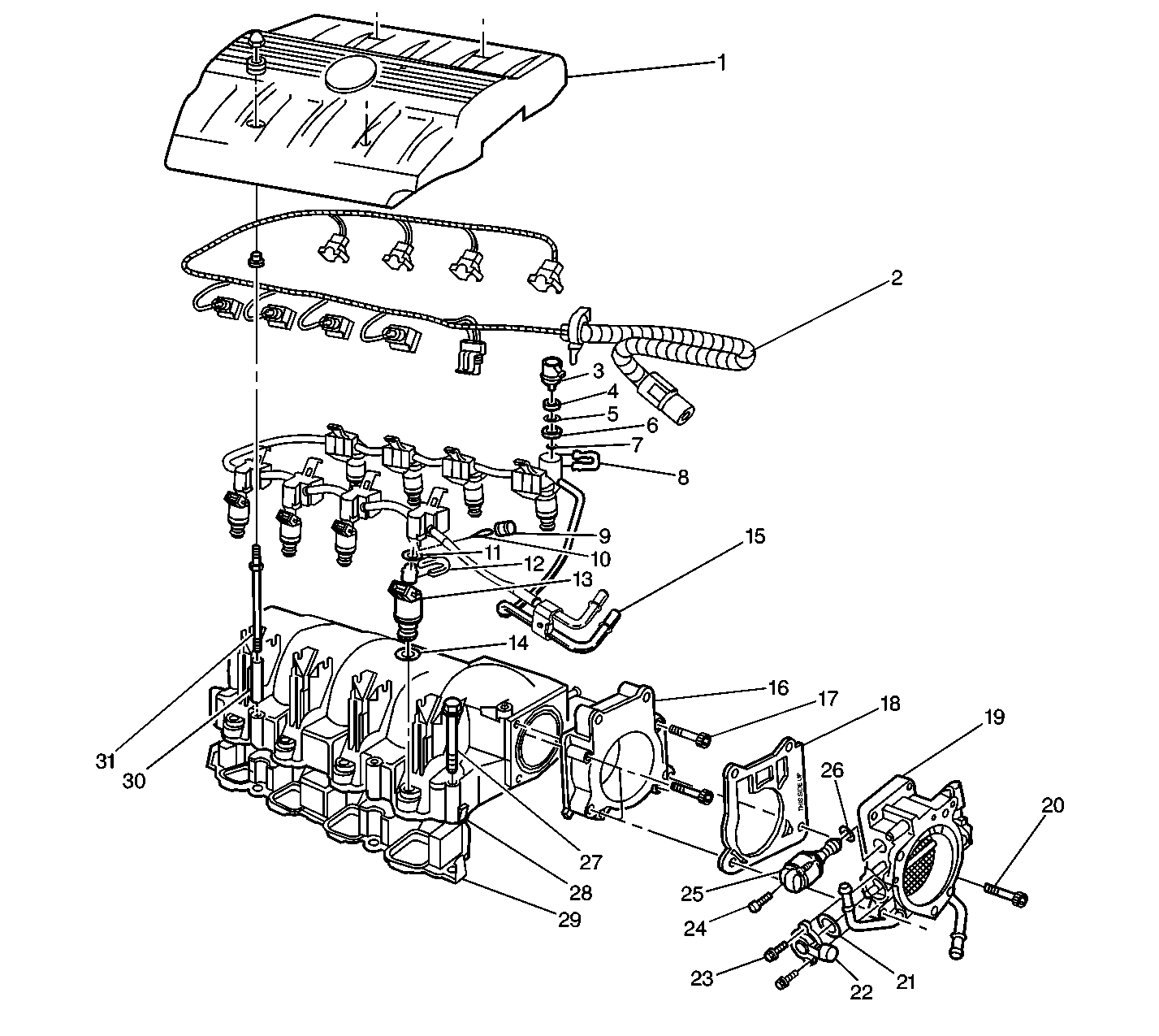
The throttle body contains a single throttle valve which controls the amount of air delivered to the engine. A coolant passage under the throttle valve heats the throttle body.

The Throttle Position (TP) sensor and Idle Air Control (IAC) valve are mounted on the throttle body. The TP sensor and minimum air stop are not adjustable.

Idle Air Control (IAC) Valve


Object Number: 10172  Size: SH
(1)IAC Valve Assembly
(2)Throttle Blade
(3)Pintle

The purpose of the Idle Air Control (IAC) Valve is to control engine idle speed, while preventing stalls due to changes in engine load.

The throttle blade when closed allows a small amount of air into the intake manifold. However, most of the air for closed throttle engine operation passes through the IAC valve, bypassing the throttle blade. The IAC valve, mounted in the throttle body, controls air flow with a conical valve or pintle. By moving the pintle in towards the seat, air flow is decreased. By moving the pintle out away from the seat, air flow is increased.

The PCM moves the IAC pintle out if engine speed is too low or in if engine speed is too high. The PCM controls IAC valve movement in small steps called counts. The IAC valve position, measured in counts away from the valve seat, can be displayed on the scan tool.

The scan tool displays IAC position in counts. 0 counts indicates the PCM is commanding the IAC to be driven all the way into a fully seated position. This is usually caused by a vacuum leak.

The higher the number of counts, the more air is being commanded to bypass the IAC pintle. 320 counts indicates a fully open position.

Prior to starting the engine and at idle, the PCM calculates the desired position of the IAC valve based on coolant temperature, engine load, engine speed and battery voltage. While the throttle position is off idle, the IAC valve position follows or tracks throttle position to allow for smooth transitions from open to closed throttle.

If the IAC valve is disconnected or disabled with the engine running, the PCM may loose track of the IAC valve position causing erratic or incorrect idle speed. If this occurs, reset the IAC valve by doing the following:

  1. The coolant temperature must be above 0°C (32°F)
  2. The vehicle must be in Park (P) not Neutral (N)
  3. Turn the ignition switch to Lock for 20 seconds

Powertrain Control Module (PCM)


Object Number: 142193  Size: SH
(1)Powertrain Control Module
(2)Air Inlet Housing

The PCM receives data from various information sensors, determines the required fuel and idle speed values and then controls the IAC valve, eight fuel injectors, and spark advance to maintain the optimum performance and driveability under all driving conditions. For more information on the PCM, refer to Powertrain Control Module Diagnosis .

The fuel pump relay allows the fuel pump to be energized by the PCM. When the ignition is first turned On, the PCM energizes the fuel pump relay for two seconds. This allows the fuel pump to run for two seconds and build up fuel pressure for cranking. The PCM then waits for ignition reference pulses from the Ignition Control Module (ICM). Once the PCM sees references pulses, the PCM energizes the relay to run the fuel pump.

A faulty fuel pump relay may cause long cranking times and should set a DTC.

Engine Coolant Temperature (ECT) Sensor


Object Number: 20478  Size: SH

The ECT sensor is a thermistor (a resistor which changes value based on temperature) mounted in the engine coolant flow. At cold coolant temperatures, the ECT sensor resistance is high and at hot coolant temperatures, the resistance of the sensor is low. The PCM supplies a 5 volt reference signal and a ground to the sensor and measures the voltage signal as it is changed by the sensor. The voltage is close to 5 volts at cold temperatures and close to zero volts at hot temperatures.

The PCM uses ECT information for fuel enrichment, ignition control, canister purge control, idle speed control and Closed Loop fuel control. A faulty ECT sensor may cause various driveability conditions and should set a PCM Trouble Code.

Ignition Control Module (ICM)

The ICM provides the PCM with engine speed (4X REF HI), fuel control (1/2X CAM HI), ignition control (Bypass and Ignition Control) and ground reference (REF LO/CAM LO) information. The ICM also provides the PCM with a signal to indicate if the ICM has identified a problem with one of its three sensors (24X Crank). All of these signals are varying voltages that have a maximum of 5 volts.

The PCM uses ICM information for fuel control, idle speed control and ignition control (which it outputs back to the ICM). A fault with any of these signals between the ICM and PCM will cause various driveability conditions and should set a DTC.

Intake Air Temperature (IAT) Sensor


Object Number: 104644  Size: SH
(1)IAT Sensor
(2)MAF Sensor
(3)Air Cleaner Cover

The IAT sensor is a thermistor (a resistor which changes value based on temperature) mounted inside of the air cleaner and measures the air temperature entering the engine. At cold air temperatures, the IAT sensor resistance is high and at hot air temperatures, the resistance of the sensor is low. The PCM supplies a 5 volt reference signal and a ground to the sensor and measures the voltage signal as it is changed by the sensor. The voltage is close to 5 volts at cold temperatures and close to zero volt at hot temperatures.

Manifold Absolute Pressure (MAP) Sensor


Object Number: 142212  Size: SH
(1)MAP Sensor Electrical Connector
(2)MAP Sensor
(3)Intake Manifold

The MAP sensor is mounted on top of the intake manifold and measures the changes in intake manifold pressure which result from engine speed and load changes. The PCM supplies a 5 volt reference signal and a ground to the sensor and the sensor outputs another voltage signal that is proportional to the pressure signal. A high pressure (low vacuum) will produce a signal close to 5 volts and a low pressure (high vacuum) will produce a signal under one volt. The PCM scales the MAP sensor signal in kilo-Pascals (kPa). The MAP signal is the Inverse of what is read on a vacuum gauge. When the MAP value is high, intake vacuum with a vacuum gauge will be low.

The PCM uses MAP information for EGR control and diagnostics. MAP information is also used to determine barometric pressure and for ignition control. A faulty MAP sensor may cause various driveability conditions and should set a DTC.

Mass Air Flow (MAF) Sensor


Object Number: 14079  Size: SH

The Mass Air Flow (MAF) sensor is located in the MAF sensor between the air snorkel and the throttle body. It senses the amount of air entering the intake manifold. This information is required by the PCM to control fuel and emissions.

The MAF sensor used on this vehicle is a hot wire type and is used to measure air flow rate (mass/unit time). The MAF sensor output is a variable frequency square wave based on air mass traveling through the sensor. A low frequency output signal from the MAF sensor indicates low air flow and high frequency indicates high air flow. The MAF sensor has two wires crossing the air stream through it. One senses ambient temperature and the other, the hot wire, is kept at a fixed temperature above the ambient temperature. The MAF sensor senses air flow by measuring the power necessary to keep the hot wire hot, which is proportional to air flow, and converts it to a frequency modulate output signal.

Oxygen Sensors


Object Number: 20422  Size: LH
(1)Cylinder Head
(2)Front Exhaust Manifold
(3)Oxygen Sensor - Bank 2 Sensor 1
(4)Cylinder Head
(5)Oxygen Sensor - Bank 1 Sensor 1
(6)Rear Exhaust Manifold
(7)Y-Pipe
(8)Oxygen Sensor - Bank 1 Sensor 2
(9)Catalytic Converter
(10)Oxygen Sensor - Bank 1 Sensor 3

Four oxygen sensors are mounted in the exhaust system where they monitor the oxygen content in the exhaust stream. There is an oxygen sensor mounted in each exhaust manifold, the exhaust manifold are bolted on to the cylinder head, and one on each end of the catalytic converter. The oxygen sensor located in the front exhaust manifold is the Bank 2 Sensor 1 (Front) sensor. The oxygen sensor located in the rear exhaust manifold is the Bank 1 Sensor 1 (Rear) sensor. The oxygen sensor located in the Y-pipe ahead of the catalytic converter is the Bank 1 Sensor 2 (Pre-converter) sensor. The oxygen sensor located in the catalytic converter outlet is the Bank 1 Sensor 3 (Post-converter) sensor.

An oxygen sensor acts like a battery because it creates its own signal voltage once it reaches operating temperature. This voltage is produced when the oxygen content in the exhaust stream is different than the oxygen content in the atmosphere. A lean condition (high oxygen content in exhaust) will produce a low voltage (near 0 volts) and a rich condition (low oxygen content in exhaust) will produce a high voltage (near one volt). The PCM provides a reference signal voltage (0.45 volts) and a ground to the sensor. The PCM reference voltage is necessary because the oxygen sensors do not provide their own voltage until they reach operating temperature.

The oxygen sensors also incorporate a heating element inside of the sensor housing. This heating element is energized with the ignition On and allows the sensors to reach operating temperatures quickly. The PCM can then use oxygen sensor information sooner after engine startup.

The PCM uses oxygen sensor information during Closed Loop operation to constantly adjust fuel control to reduce exhaust emissions. Because the oxygen sensors provide information sooner after engine start-up, exhaust emissions are reduced. Faulty oxygen sensors will cause various driveability conditions and should set a DTC.

Power Steering Pressure Switch


Object Number: 142263  Size: SH
(1)Power Steering Hose
(2)Power Steering Pressure Sensor Switch
(3)Power Steering Pressure Sensor Switch Connector

The power steering pressure switch is located on the power steering pressure hose between the power steering pump and rack and pinion gear. The power steering pressure switch is normally closed and provides a battery voltage signal to the PCM with no power steering load. When power steering pressure increases to a calibrated level due to steering load (such as full steering lock), the switch opens and causes the signal voltage to the PCM to drop to 0 volt.

The PCM uses the power steering pressure switch signal for idle speed control during high steering loads to maintain a stable idle. A shorted power steering pressure switch may cause a stumble or stall during steering loads and an open switch should set a DTC.

Throttle Position (TP) Sensor


Object Number: 18398  Size: SH
(1)Valve Assembly -- Idle Air Control
(2)Sensor -- Throttle Position
(3)Screws -- Throttle Position Sensor Attaching
(4)Screws -- Idle Air Control Valve Attaching

The TP sensor is a potentiometer that is mounted on the throttle body and provides the PCM with information on throttle valve angle. The PCM provides a 5 volt reference signal and a ground to the TP sensor and the sensor returns a signal voltage that changes with throttle valve angle. At closed throttle (close to 0 degrees) the TP sensor output signal is low (below 1 volt) and at WOT (greater than 80 degrees) the TP sensor output signal is high (above 4 volts). Because the TP sensor is not adjustable, the PCM must account for build tolerances that could affect the TP sensor output at closed throttle. The PCM uses a learning algorithm so that it can correct for variations of up to 6 degrees of throttle angle.

The PCM uses TP information to modify fuel control based on throttle valve angle. For example, power enrichment occurs when the throttle angle approaches WOT. Acceleration enrichment occurs when the throttle angle increases rapidly (similar to an accelerator pump on a carburetor). A faulty TP sensor may cause various driveability conditions and should set a DTC.

Transaxle Pressure Switch

The transaxle pressure switch is located inside of the transaxle and it composed of five discrete pressure switches that are combined to provide three status indications to the PCM. The PCM then uses these three inputs in a digital format (001, 010, 011, etc.) to determine the six possible transaxle ranges.

The PCM uses the transaxle pressure switch status for idle speed control, transaxle shift control and ignition control. A faulty transaxle pressure switch will cause various transaxle and engine driveability conditions and should set a DTC.

Transaxle Range (TR) Switch

The TR switch (formerly called a PRNDL, P/N or NSBU switch) is mounted externally on the transaxle at the manual shaft. The TR switch provides information to the PCM about the selected gear range of the transaxle. The TR switch identifies whether the transaxle is in Park/Neutral (P/N) or any of the five drive ranges (R/D4/D3/D2/D1). The TR switch is also used to illuminate the backup lamps when the transaxle is in Reverse (R).

The PCM uses TR switch status for idle speed control, and also as a backup to the transaxle pressure switch. If the transaxle pressure switch is faulty, the PCM will select a transaxle gear based on TR switch status. A faulty TR switch should set a DTC.

Vehicle Speed Sensor (VSS)

The vehicle speed sensor (VSS) is a pulse generator mounted in the transaxle. A toothed reluctor ring rotates near a magnetic pickup which produces a varying voltage signal in the pickup coil. This voltage signal varies in proportion to vehicle speed and is sent to the PCM, where it is converted to MPH.

The PCM uses VSS information for fuel economy calculations, idle speed control, transaxle shifts, and to control fuel under certain conditions. A faulty VSS may cause various transaxle and engine driveability conditions and should set a DTC.

Accelerator Controls


Object Number: 104758  Size: SH
(1)Fuel Pipe Retainer
(2)Accelerator Controls Cable
(3)Accelerator Controls Bracket

The accelerator control system is cable type. There are no linkage adjustments. Therefore, the specific cable for each application must be used. The accelerator cable is routed through the groove in the throttle body lever.


Object Number: 12238  Size: SH
(1)Accelerator Control Cable
(2)Accelerator Pedal Assembly
(3)Accelerator Pedal Retainer

When work has been performed on accelerator controls, always make sure that all components are installed correctly and that linkage and cables are not rubbing or binding in any manner. The throttle should operate freely without bind between full closed and wide open throttle.

The air cleaner element, housing and ducts provide the engine with clean, filtered intake air for the combustion process. A flat air filter element provides maximum air filtration with minimum flow restriction. The air cleaner housing and ducts are designed to allow the maximum air flow possible with a minimum of noise produced and to reduce the potential for water ingestion into the engine.

Insure that the duct to the throttle body and air cleaner housing is properly seated and secured and that the air cleaner housing is latched together properly. An incorrectly assembled air cleaner system may cause excessive noise or may allow unfiltered air to enter the engine. Also, incorrectly installed air cleaner systems may cause fueling or driveability problems by affecting air-flow at the MAF sensor.