Circuit Description
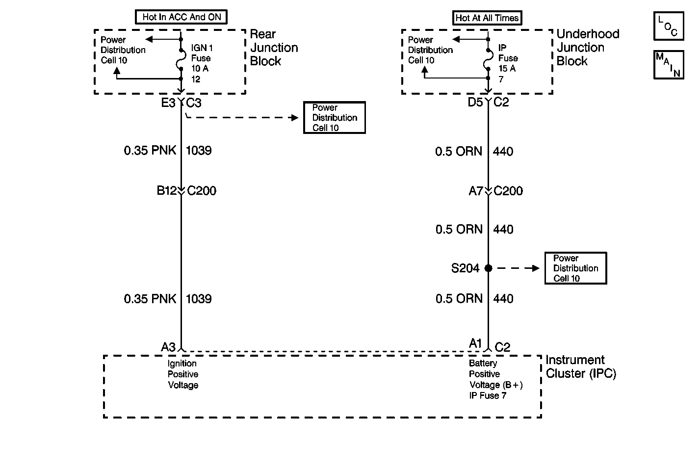
The battery positive voltage (B+) is supplied to the Instrument Cluster (IPC) on CKT 440 (ORN) at connector C2 terminal A1. The IPC monitors this voltage to determine if it is within a valid operating range and the alternator is operating properly.
Conditions for Setting the DTC
| • | The battery positive voltage (B+) level falls below 9 volts for approximately 1.2 seconds or more. |
| • | Engine RPM is greater than 1500 rpm. |
| • | The alternator is not operating properly. The IPC receives this status from the Powertrain Control Module (PCM) via Class 2 message. |
Action Taken When the DTC Sets
| • | DTC B1981 is stored in the IPC memory. |
| • | The IPC does not respond to inputs when the voltage is less than 9 volts. |
| • | BATTERY VOLTAGE LOW message is displayed on the DIC. |
| • | DTC B1983 does not set when DTC B1981 is current. |
| • | Other IPC DTCs do not set while DTC B1981 is current. |
Conditions for Clearing the DTC
| • | This DTC clears (status changes from current to history when the Battery Positive Voltage (B+) level rises above 9.5 volts for approximately 1.2 seconds and alternator output, as reported by the PCM, is normal. |
| • | A history DTC clears after 50 consecutive ignition cycles if the conditions for setting the DTC are no longer present. |
| • | Current and history DTCs may be cleared using a scan tool or using the IPC on-board clearing DTCs feature. |
Diagnostic Aids
The IPC does not check for low battery positive voltage (B+) during and for 2 seconds following the engine START mode. This delay ensures that DTC B1981 will not erroneously set.
Test Description
The numbers below refer to the step numbers on the diagnostic table:
-
Perform the Instrument Cluster (IPC) Diagnostic System Check before continuing with the diagnosis of this DTC.
-
Checks that DTC was not set erroneously.
-
Determines whether the malfunction is in the charging system or the Instrument Cluster (IPC).
-
Clear all DTCs after the repair procedure is complete.
Step | Action | Value(s) | Yes | No |
|---|---|---|---|---|
Was the Instrument Cluster (IPC) Diagnostic System Check performed? | -- | |||
Is the Battery Positive Voltage (B+) greater than the specified value? | 9.5 V | |||
Is the measured voltage less than the specified value? | 9.5 V | Refer to Charging System Check in Engine Electrical | ||
4 | Replace the Instrument Cluster (IPC). Refer to Instrument Cluster Replacement . Is the module replacement complete? | -- | -- | |
Are all DTCs cleared? | -- | -- |
