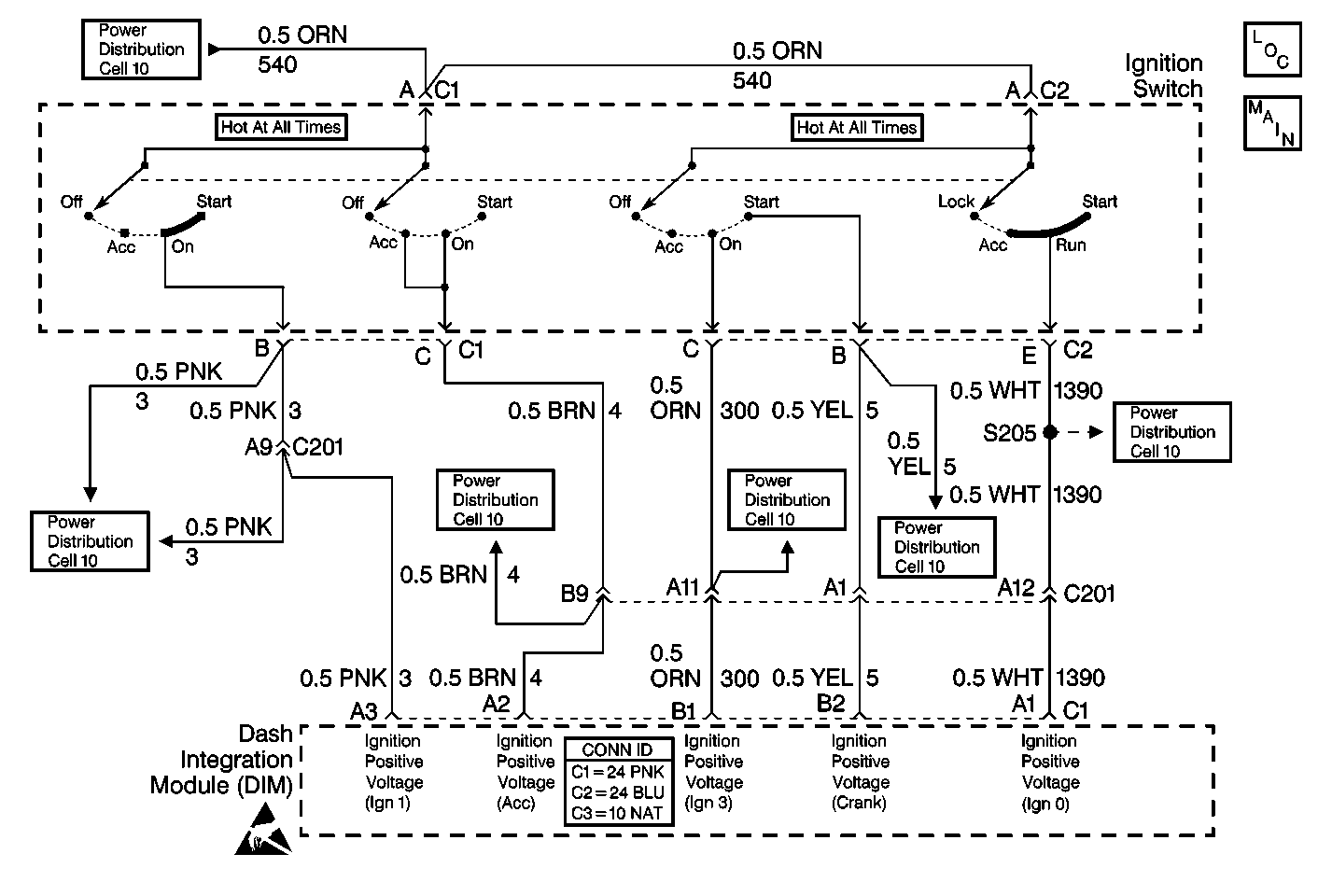
Circuit Description
The Dash Integration Module (DIM) determines the state of the ignition switch from several circuits wired from the ignition switch to the DIM. These circuits are as follows:
| • | Ignition positive voltage (IGN1 -- Run/Crank) on CKT 3 (PNK). |
| • | Ignition positive voltage (IGN0 -- Acc/Run/Crank) on CKT 1390 (WHT). |
| • | Ignition positive voltage (IGN3 -- Run) on CKT 300 (ORN). |
| • | Ignition positive voltage (Run/Acc) on CKT 4 (BRN). |
| • | Ignition positive voltage (Crank) on CKT 5 (YEL). |
There are 32 possible ignition switch state combinations, including all possible failure conditions. Five of these combinations represent valid ignition switch states, and four others are between switch detent positions which can be assigned valid states. All others represent failure conditions. The DIM checks for these invalid ignition switch state combinations.
Conditions for Setting the DTC
| • | DTC B1805 only sets if B1982 or B1983 is not current in DIM memory. |
| • | DTC B1805 sets if the DIM determines that an invalid ignition switch state exists. |
Action Taken When the DTC Sets
| • | DTC B1805 is stored in DIM memory. |
| • | The DIC displays the IGNITION SWITCH PROBLEM message. |
| • | The DIM maintains the same power mode information (ignition switch states sent by the DIM via Class 2 messages) it had before the DTC set. |
Conditions for Clearing the DTC
| • | DTC B1805 clears (status changes from current to history) when the DIM no longer detects an invalid ignition switch state. |
| • | A history DTC clears after 50 consecutive ignition cycles if the condition for the malfunction is no longer present. |
| • | Use the On-Board clearing DTCs feature. Refer to Diagnostic Trouble Code (DTC) Clearing in HVAC Systems with A/C - Automatic. |
| • | Use a scan tool. |
Diagnostic Aids
Refer to Power Distribution in Wiring Systems for complete electrical schematic diagrams of the ignition switch wiring.
Test Description
The numbers below refer to the step numbers on the diagnostic table:
-
Perform the Body Control Module Diagnostic System Check before continuing with the diagnosis of this DTC.
-
Clear all DTCs and cycle ignition to check that the DTC did not falsely set.
-
Clear all DTCs after the repair procedure is complete.
Step | Action | Value(s) | Yes | No |
|---|---|---|---|---|
Was the Body Control Module Diagnostic System Check performed? | -- | |||
Is the DTC still present? | -- | System OK | ||
3 |
Is each input active, as displayed on the scan tool, for its corresponding ignition switch position(s)? | -- | ||
4 |
Is the voltage above the specified value with the ignition switch in ON and START? | 10.5 V | ||
5 | Check CKT 3 (PNK) for an open or short to ground. Is circuit OK? | -- | ||
6 | Repair CKT 3 (PNK). Is circuit repair complete? | -- | -- | |
7 | Using a DMM, check the voltage from DIM connector C1 terminal A2 to ground. Is the voltage above the specified value with the ignition switch in ACC and ON? | 10.5 V | ||
8 | Check CKT 4 (BRN) for an open or short to ground. Is circuit OK? | -- | ||
9 | Repair CKT 4 (BRN). Is circuit repair complete? | -- | -- | |
10 | Using a DMM, check the voltage between DIM connector C1 terminal B2 and ground. Is the voltage above the specified value with the ignition switch in START? | 10.5 V | ||
11 | Check CKT 5 (YEL) for an open or short to ground. Is circuit OK? | -- | ||
12 | Repair CKT 5 (YEL). Is circuit repair complete? | -- | -- | |
13 | Using a DMM, check the voltage between DIM connector C1 terminal B1 and ground. Is the voltage above the specified value with the ignition switch in ON? | 10.5 V | ||
14 | Check CKT 300 (ORN) for an open or short to ground. Is circuit OK? | -- | ||
15 | Repair CKT 300 (ORN). Is circuit repair complete? | -- | -- | |
16 | Using a DMM, check the voltage at DIM connector C1 terminal A1. Is the voltage above the specified value with the ignition switch in ON, START and ACC? | 10.5 V | ||
17 | Check CKT 1390 (WHT) for an open or short to ground. Is circuit OK? | -- | ||
18 | Repair CKT 1390 (WHT). Is circuit repair complete? | -- | -- | |
19 | Check ignition switch connector for poor terminal contact. If OK, replace ignition switch. Refer to Ignition and Start Switch Replacement in Instrument Panel, Gauges and Console. Is switch replacement complete? | -- | -- | |
20 | Check DIM connector C1 for poor terminal contact. If OK, replace DIM. Refer to Body Control Module Replacement . Is module replacement complete? | -- | -- | |
Are all DTCs cleared? | -- | -- |
