Refer to Body Control Module Schematics,
Cell 51: DIM Power and Ground
.
Circuit Description
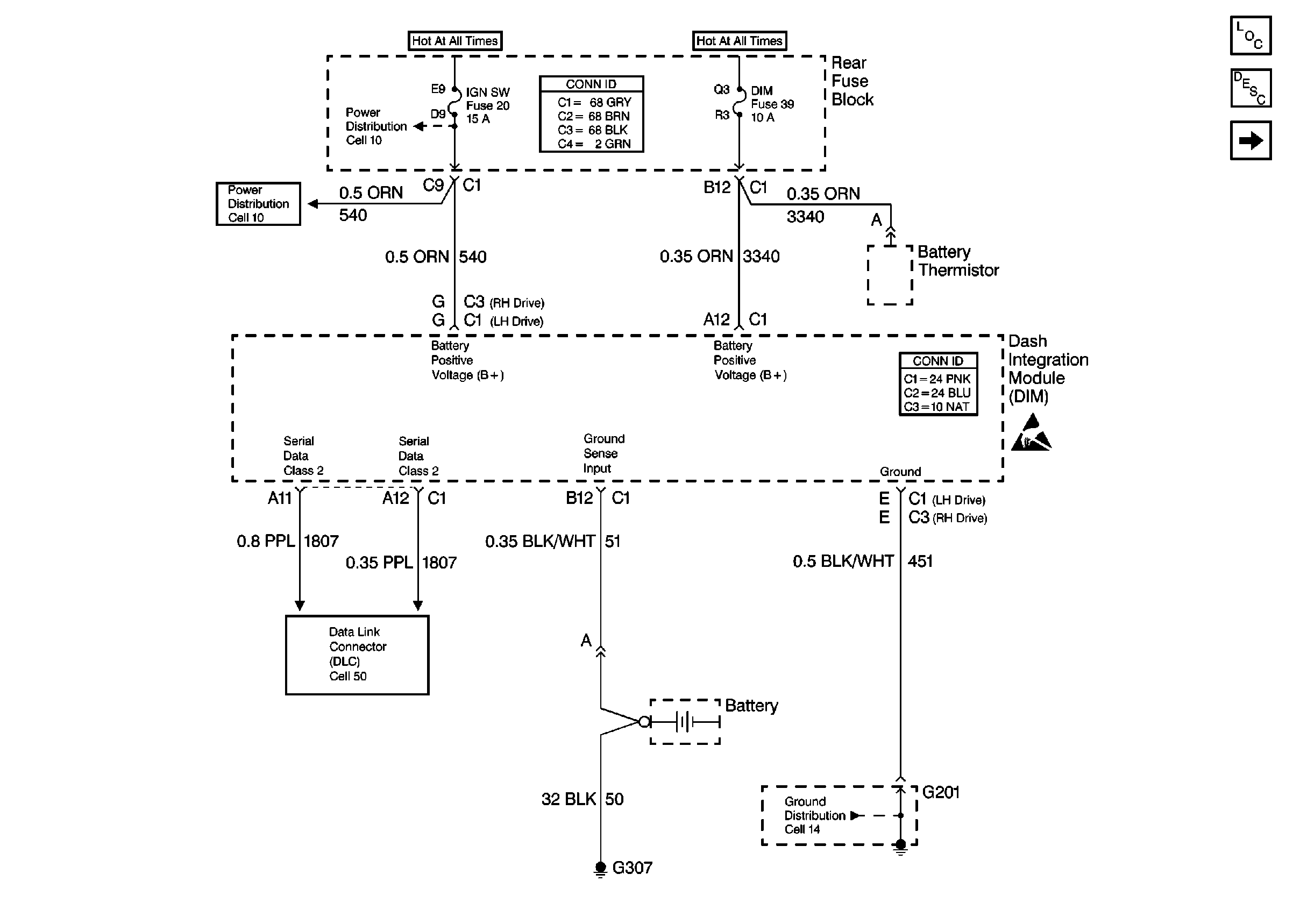
Power is provided from the dash integration module (DIM) fuse on CKT 3340 (ORN) to the battery positive voltage sense input of the DIM at connector C1 terminal A12. This voltage input is referenced to the ground sense input, CKT 51 (BLK/WHT) at DIM connector C1 terminal B12. The sense inputs accurately measure battery voltage. The most important use of this function is to determine if the battery is charging or discharging for the DIM load management function.
Conditions for Setting the DTC
The battery sense voltage is greater than 24.0 volts or less than 7.5 volts and the ignition positive voltage (IGN1) is in the range of 8.5 volts to 16.5 volts.
Action Taken When the DTC Sets
| • | DTC B1390 is stored in DIM memory. |
| • | This DTC does not cause a warning message to be displayed. |
Conditions for Clearing the DTC
| • | DTC B1390 clears (status changes from current to history) when the DIM no longer detects the conditions which caused the DTC to set. |
| • | A history DTC clears after 50 consecutive ignition cycles if the condition for the malfunction is no longer present. |
Diagnostic Aids
The DIM will not check for low Battery Positive Voltage (B+) during and for two seconds following the engine CRANK mode.
Test Description
The numbers below refer to the step numbers on the diagnostic table:
-
Perform the Dash Integration Module (DIM) Diagnostic System Check before continuing with the diagnosis of this DTC.
-
Checks that DTC was not set erroneously.
-
Determines whether the malfunction is in the charging system or the DIM.
-
Clear all DTCs after the repair procedure is complete.
Step | Action | Value(s) | Yes | No |
|---|---|---|---|---|
Was the Body Control Module Diagnostic System Check performed? | -- | |||
Is the voltage within the specified range? | 7.5 to 24 V | Go to Step 3 | Refer to Charging System Check in Engine Electrical | |
Is the ignition positive voltage (IGN1) within the specified range? | 8.5 to 16.5 V | Refer to Charging System Check in Engine Electrical | ||
4 | Replace the DIM. Is the repair complete? | -- | -- | |
Are all DTCs cleared? | -- | -- |
