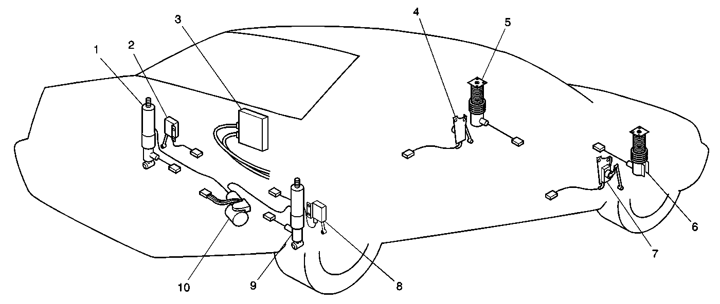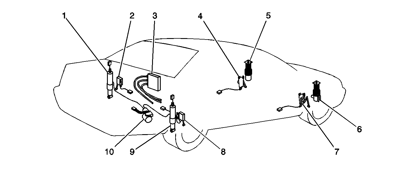

There are two Electronic Suspension Control (ESC) systems that are being used in the Seville. The Continuously Variable Road Sensing Suspension (CVRSS) is used in the early models and is designated as RPO F45. The Magnito-Reheological Real Time Damping (MRRTD) system, also known as Magnetic Ride Control is used in the later models and is designated as RPO F55. The name Electronic Suspension Control (ESC) is being used throughout the service manual to avoid confusion as to what system is being used. Both systems electrical function is basically the same and they are diagnosed the same.
The Electronic Suspension Control (ESC) system consists of the following components:
| • | ESC module (3) |
| • | Four dampers contained in the 2 front struts (5 and 6) and the 2 rear shock absorbers (1 and 9) |
| • | Four positions sensors (2,4,7, and 8) |
| • | ALC air compressor module (10) |
| • | Damper relay (not shown) for RPO F45 only |
| • | ELC relay (not shown) |
The ESC system with rear Automatic Level Control (ALC) controls damping forces in the front struts and rear shock absorbers in response to various road and driving conditions. The rear ALC portion of the system maintains a proper vehicle trim height under various vehicle load conditions. For more information on the ALC, refer to Automatic Level Control Description and Operation in Automatic Level Control.
The ESC module receives the following inputs: wheel-to-body position, vehicle speed, and lift/dive. The ESC module evaluates these inputs and controls actuators in each of the dampers independently to provide varied levels of suspension control.
Electronic Suspension Control (ESC) Module
The ESC module is used to control how firm or soft each shock or strut should be to provide the best ride. The ESC module is also used to control the vehicles rear height. The ESC module is located on the right side of the rear seat back and is accessed through the trunk.
The differences between RPO F45 and RPO F55 modules are as follows:
- F45 ESC module has two connectors, a 24-pin and a 32-pin.
- F55 ESC module has three connectors, a 5-pin, a 24-pin and a 32-pin.
- F45 Damper relay is external to ESC module.
- F55 Damper relay is internal in ESC module.
- F45 ESC module sets DTCs C0690, C0691 and C0693. These DTCs refer to damper relay faults.
- F55 ESC module sets DTCs C0690, C0691, or C0693. These DTCs refer to an ESC module failure.
- F45 ESC module sets DTCs C0577, C0578, C0579, C0582, C0583, C0584, C0587, C0588, C0589, C0592, C0593, or C0594. These DTCs refer to damper actuator faults.
- F55 ESC module sets DTCs C0577, C0579, C0582, C0584, C0587, C0589, C0592, or C0594. These DTCs refer to damper actuator faults.
- F55 ESC module sets DTCs C0578, C0583, C0588, or C0593. These DTCs refer to an ESC module failure.
Position Sensors
The position sensors are 0 to 5 volt DC output devices that are used to measure wheel-to-body movement/position. There are four position sensors on the vehicle, one per corner. Each position sensor is mounted between a suspension control arm and the body.
Shock Absorber or Strut
An ESC damper is mounted at each corner of the vehicle. The four suspension dampers, 2 front struts and 2 rear shock absorbers, each contain an integral actuator that is controlled by the ESC module. The actuator provides a wide range of damping forces between soft and firm levels. Damping is controlled by the amount of current supplied to the actuator. The ESC module controls the current flow to the actuator via pulse width modulation.
(F45) The CVRSS damper uses the applied magnetic field to increase or decrease the size of the damper orifice. The orifice in turn, allows oil through to either cause the dampers to be soft or firm, depending on how much current was applied by the ESC module. The total response time for the damper is less than 10 msec.
(F55) The MRRTD damper uses the applied magnetic field to align the metal particles in the MR fluid. The damper in turn, delivers a soft of firm ride, depending on how much current was applied by the ESC module. The MR effect response time is less than 1 msec.
Vehicle Speed
The ESC module receives a vehicle speed input. It is obtained over the CLASS 2 serial communication buss. Vehicle speed is used to determine the amount of damper control necessary.
Lift/Dive
Lift/Dive input is received from the PCM. When the ESC module receives an active lift/dive input, it will command a firm damping level on all four corners. The lift signal is calculated in the PCM based on throttle position, transmission gear, vehicle speed, and brake switch status. The dive signal, also calculated in the PCM, is based upon the rate of change with the vehicle speed.
Warning Messages
The DIC displays two different warning messages that are set if there is an electronic suspension control system fault(s). The warning messages are as follows:
| • | SERVICE SUSPENSION SYS |
| • | SPEED LIMITED TO XXX |
The DIC will display one, both or none, depending on the fault that was encountered. The warning message(s) will continue to be displayed, until the fault(s) has been corrected.
