Ignition and Start Switch Replacement LHD
Removal Procedure
Caution: Refer to SIR Handling Caution in the Preface section.
- Apply the park brake.
- Disconnect the negative battery cable. Refer to Battery Negative Cable Disconnection and Connection in Engine Electrical.
- Disable the SIR system. Refer to Disabling the SIR System in SIR.
- Remove the radio. Refer to Radio Replacement in Entertainment.
- Remove the knee bolster. Refer to Knee Bolster Replacement .
- Disconnect the ignition switch electrical.
- Remove the lamp socket from the ignition switch.
- Turn the ignition to the run position.
- Depress the release button (1) on the park lock cable and pull the cable, in order to disconnect the park lock cable from the ignition switch.
- Look through the radio opening, and locate the ignition lock cylinder retaining tab (3).
- Using a flat-bladed too, depress and hold the ignition lock cylinder retaining tab (3)
- Remove the ignition lock cylinder from the IP.
- Remove the ignition switch fasteners (1, 4).
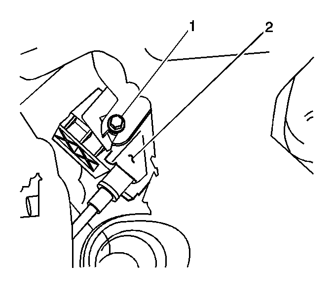
- Looking through the opening next to the steering column, remove the fastener (2) from the ignition switch (2)
- Remove the ignition switch assembly from the IP.
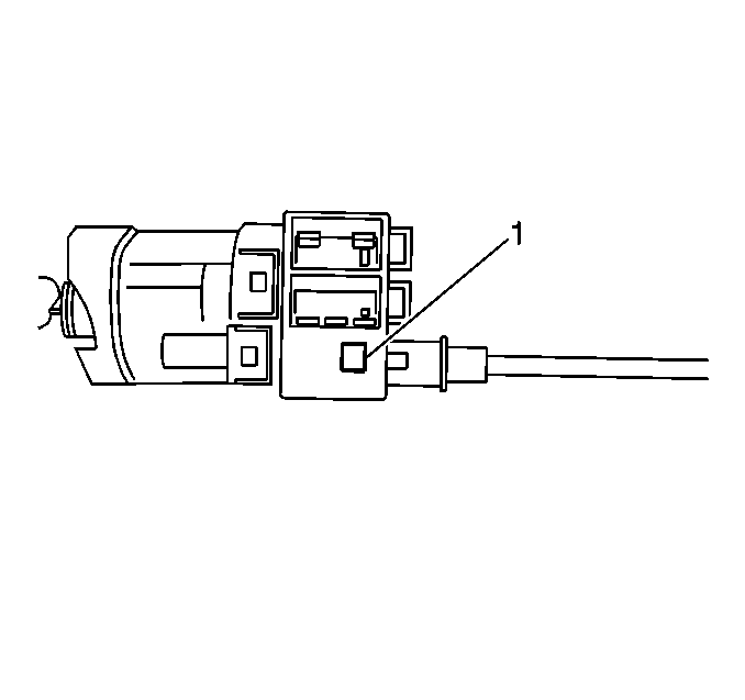
The release button (1) is located on the bottom of the ignition switch at the 6 o'clock position.
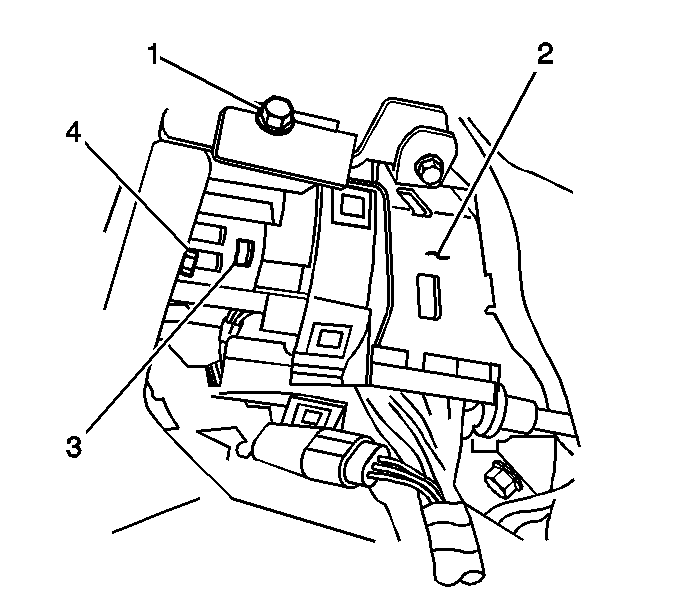
The ignition lock cylinder retaining tab (3) is located on the right lower side of the ignition switch assembly (2).
Installation Procedure
- Install the ignition switch (2) to the IP retainer.
- Through the opening next to the steering column, install the ignition switch fastener (1).
- Through the radio opening, install the ignition switch fasteners (1, 4).
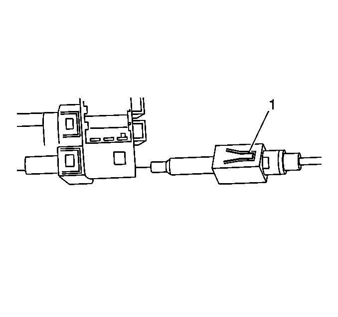
- Install the park lock cable (1) to the ignition switch.
- Connect the ignition switch electrical connectors.
- Install the lamp socket to the ignition switch.
- With the key installed in the ignition lock cylinder (1) insert the ignition lock cylinder (1) into the IP opening (2).
- Using light force, pull on the lock cylinder in order to ensure the lock cylinder is engaged.
- Turn the ignition to LOCK, then remove the key.
- Install the radio. Refer to Radio Replacement in Entertainment.
- Install the knee bolster. Refer to Knee Bolster Replacement .
- Enable the SIR system. Refer to Enabling the SIR System in SIR.
- Connect the negative battery cable. Refer to Battery Negative Cable Disconnection and Connection in Engine Electrical.
- Inspect the ignition switch for proper operation in all positions.
- Release the park brake.

Notice: Refer to Fastener Notice in the Preface section.
Tighten
Tighten the fastener to 2 N·m (18 lb in).

Tighten
Tighten the fastener to 2 N·m (18 lb in).
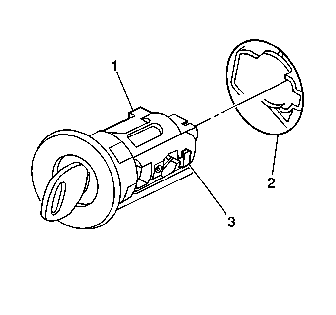
The lock cylinder retaining tab (3) will produce an audible click, when fully engaged.
Ignition and Start Switch Replacement RHD
Removal Procedure
Caution: Refer to SIR Handling Caution in the Preface section.
- Apply the park brake.
- Disconnect the negative battery cable. Refer to Battery Negative Cable Disconnection and Connection in Engine Electrical.
- Disable the SIR system. Refer to Disabling the SIR System in SIR.
- Remove the right instrument panel outer trim cover. Refer to Instrument Panel Outer Trim Cover Replacement .
- Remove the knee bolster. Refer to Knee Bolster Replacement .
- Disconnect the electrical connectors from the ignition switch.
- Remove the lamp socket from the ignition switch.
- Turn the ignition to the run position.
- Depress the release button (1) for the park lock cable and pull the cable, in order to disconnect the park lock cable from the ignition switch.
- Look through the IP outer trim panel opening and locate the ignition lock cylinder retaining tab (3).
- Using a flat-bladed tool, depress and hold the ignition lock cylinder retaining tab (3).
- Remove the ignition lock cylinder from the IP.
- Remove the ignition switch fasteners (1, 4).
- Looking through the opening next to the steering column, remove the fastener (2) from the ignition switch (2)
- Remove the ignition switch assembly from the IP.

The release button (1) is located on the bottom of the ignition switch at the 6 o'clock position.

The ignition lock cylinder retaining tab (3) is located on the right lower side of the ignition switch assembly (2).

Installation Procedure
- Install the ignition switch (2) to the IP retainer.
- Through the opening next to the steering column, install the ignition switch fastener (1).
- Through the IP outer trim panel opening , install the ignition switch fasteners (1, 4).
- Install the park lock cable (1) to the ignition switch.
- Connect the ignition switch electrical connectors.
- Install the lamp socket to the ignition switch.
- With the key installed in the ignition lock cylinder (1) insert the ignition lock cylinder (1) into the IP opening (2).
- Using light force, pull on the lock cylinder in order to ensure the lock cylinder is engaged.
- Turn the ignition to LOCK, then remove the key.
- Install the right IP outer trim panel. Refer to Instrument Panel Outer Trim Cover Replacement .
- Install the knee bolster. Refer to Knee Bolster Replacement .
- Enable the SIR system. Refer to Enabling the SIR System in SIR.
- Connect the negative battery cable. Refer to Battery Negative Cable Disconnection and Connection in Engine Electrical.
- Inspect the ignition switch for proper operation in all positions.
- Release the park brake.

Notice: Refer to Fastener Notice in the Preface section.
Tighten
Tighten the fastener to 2 N·m (18 lb in).

Tighten
Tighten the fastener to 2 N·m (18 lb in).


The lock cylinder retaining tab (3) will produce an audible click, when fully engaged.
