For 1990-2009 cars only
| Figure 1: |
MAP, IAC, ECT, TP Sensors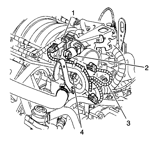
|
| Figure 2: |
EVAP Purge Solenoid, and EGR Valve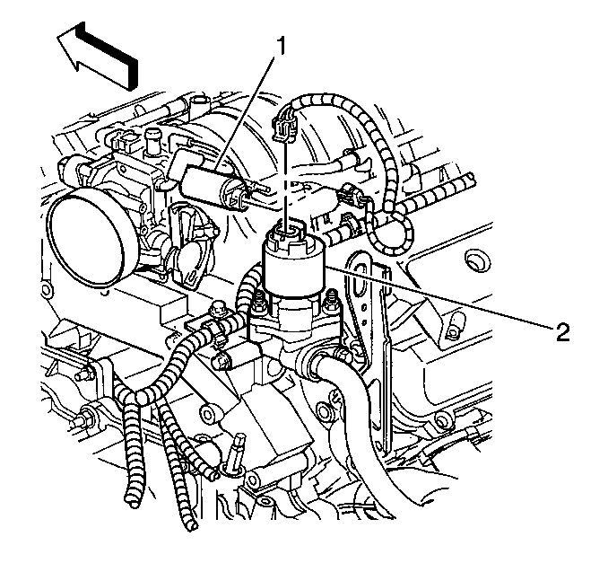
|
| Figure 3: |
CKP B, CKP A, Engine Oil Pressure Switch, and Engine Oil Level Switch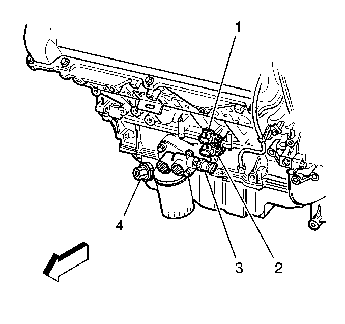
|
| Figure 4: |
Ignition Control Module (ICM) Bank 2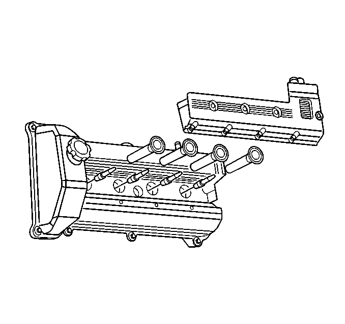
|
| Figure 5: |
Ignition Control Module (ICM) Bank 1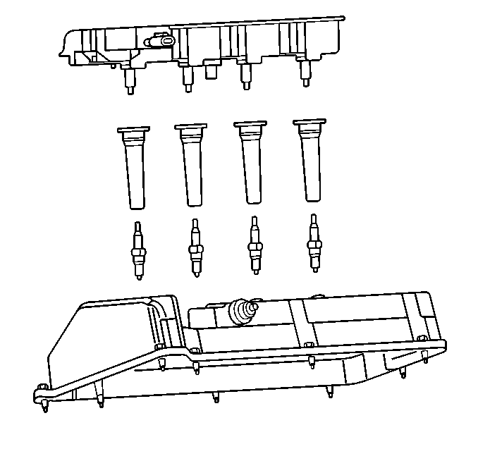
|
| Figure 6: |
CMP, VSS, and HO2S Bank 1 Sensor 1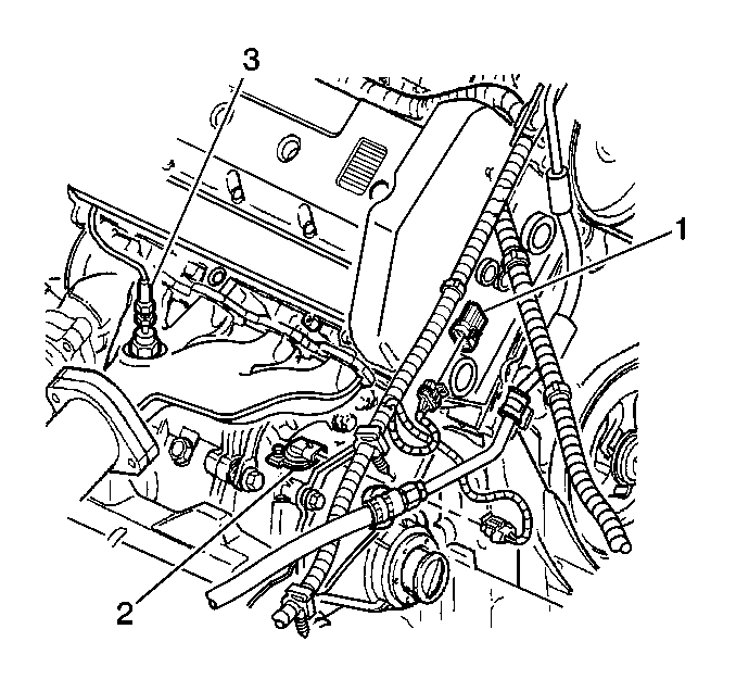
|
| Figure 7: |
Heated Oxygen Sensor (HO2S) Bank 1 Sensor 2 (Post HO2)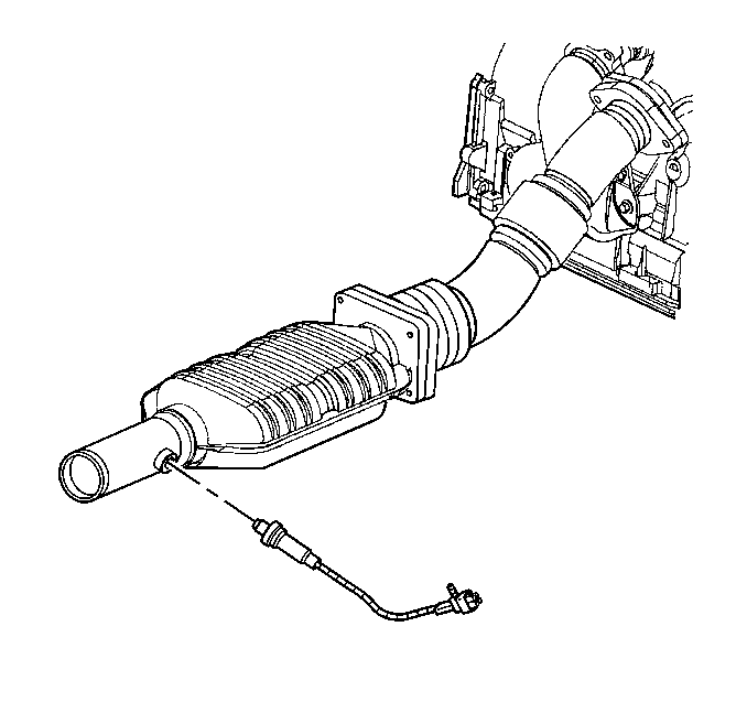
|
| Figure 8: |
Heated Oxygen Sensor (HO2S) Bank 2 Sensor 1 (Front HO2)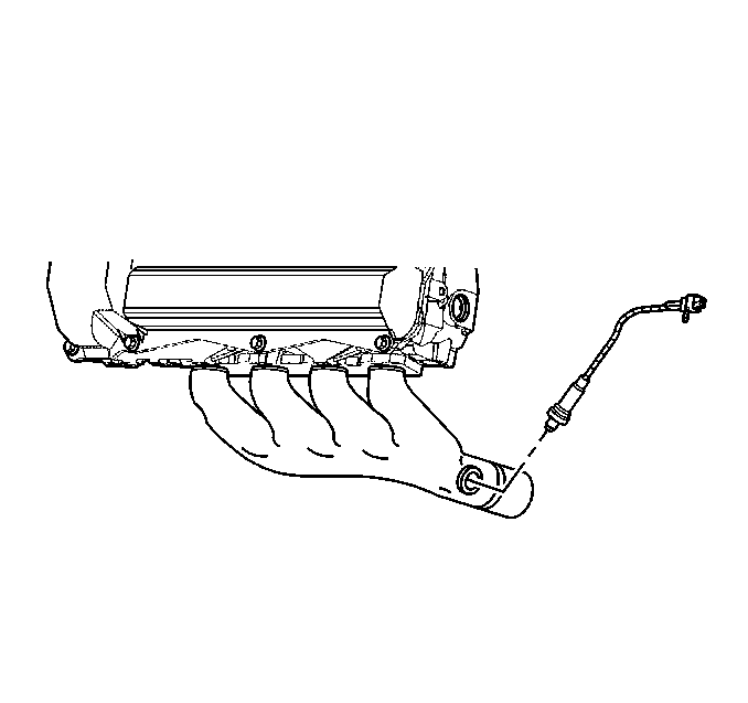
|
| Figure 9: |
Knock Sensor (KS)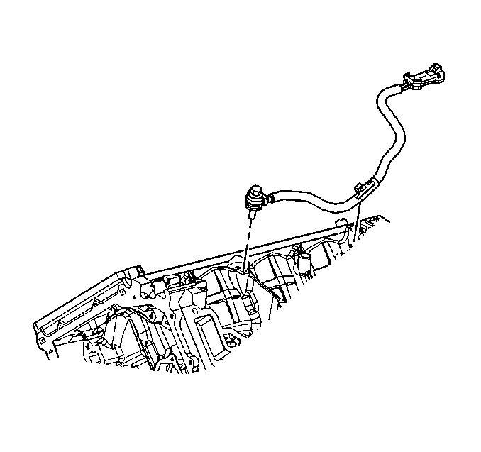
|
| Figure 10: |
AIR Relay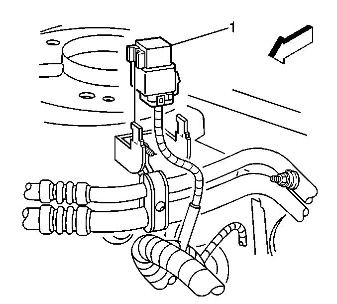
|
| Figure 11: |
Rear AIR Check Valve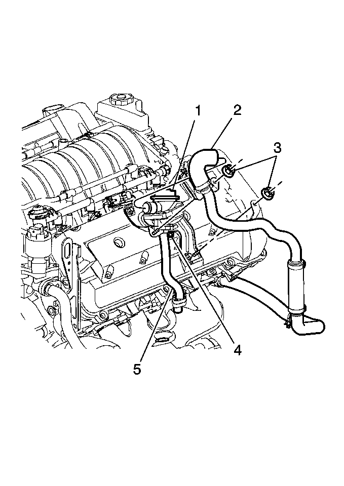
|
| Figure 12: |
AIR Vacuum Routing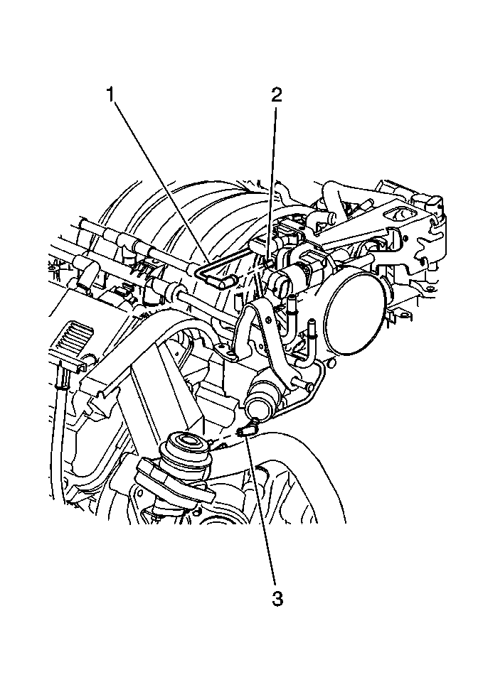
|
| Figure 13: |
AIR Vacuum Control Solenoid and Vacuum Connections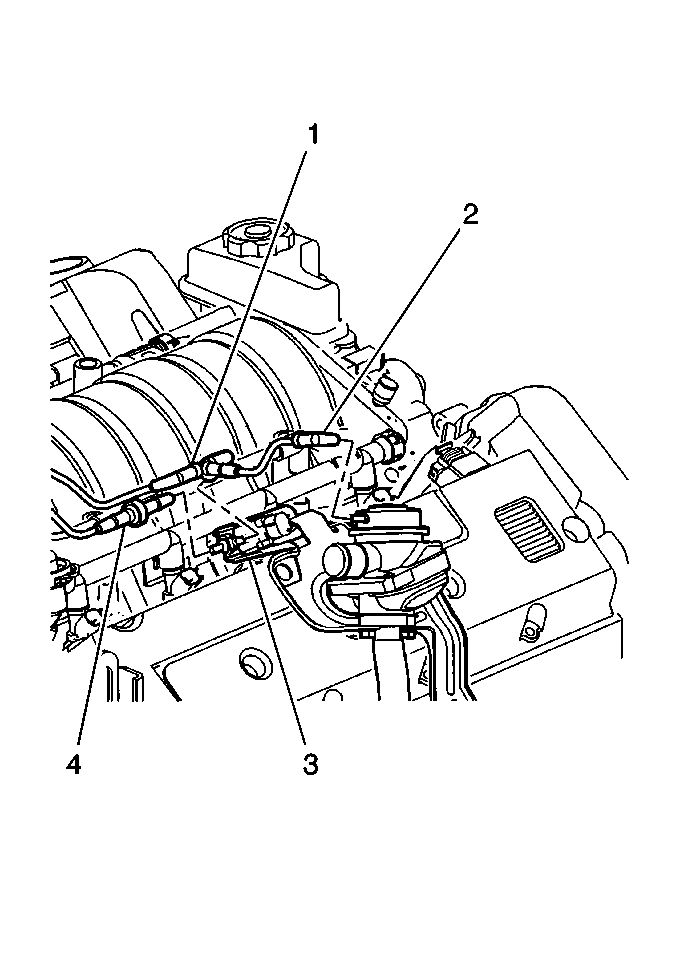
|
| Figure 14: |
Left AIR Pump and Electrical Connector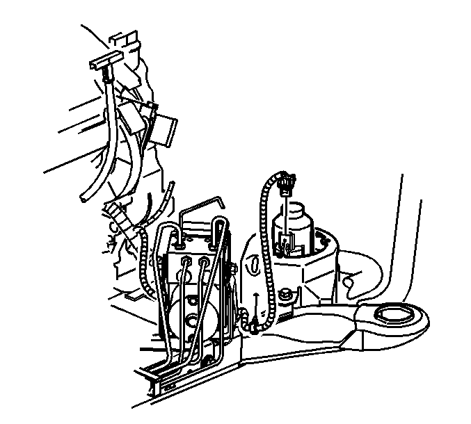
|
| Figure 15: |
Left AIR Exhaust Hose and Front AIR Check Valve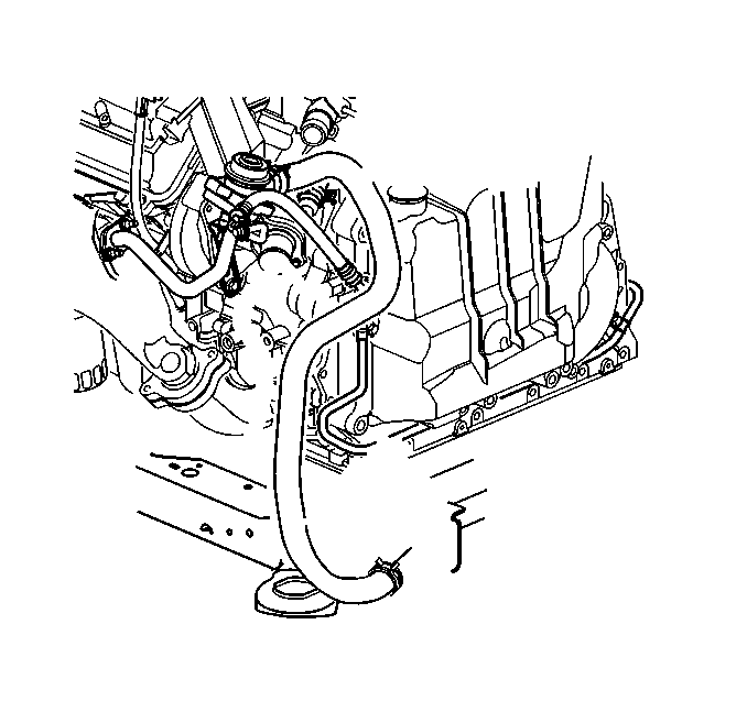
|
| Figure 16: |
Left AIR Inlet Hose to AIR Pump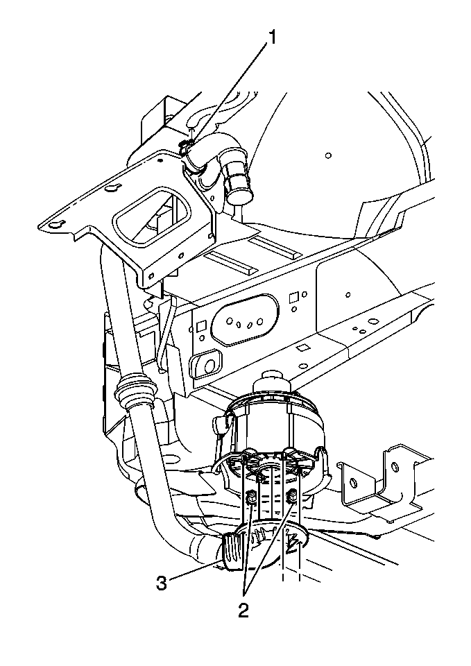
|
| Figure 17: |
Front AIR Check Valve to Exhaust Manifold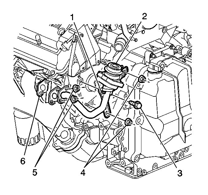
|
| Figure 18: |
IAC Valve and TP Sensor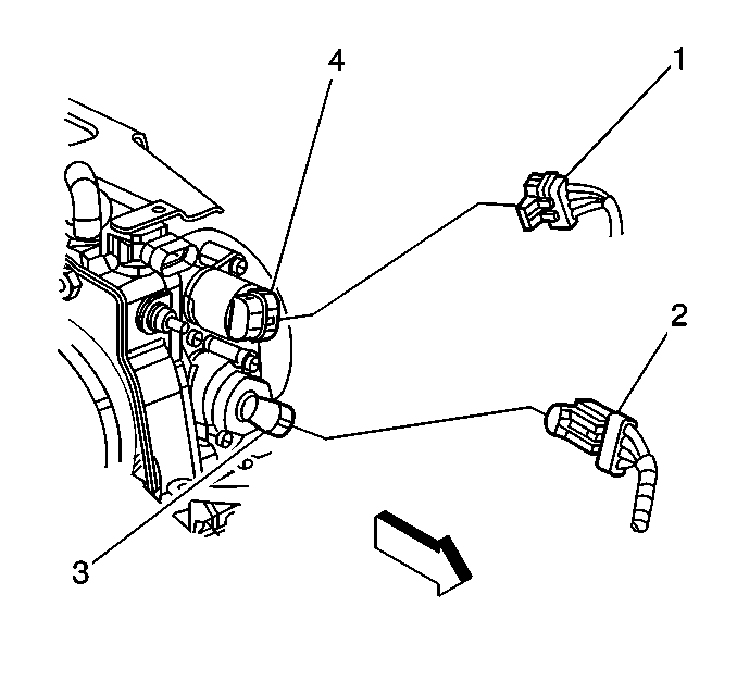
|
| Figure 19: |
Fuel Rail Assembly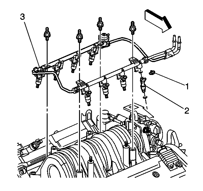
|
| Figure 20: |
Fuel Lines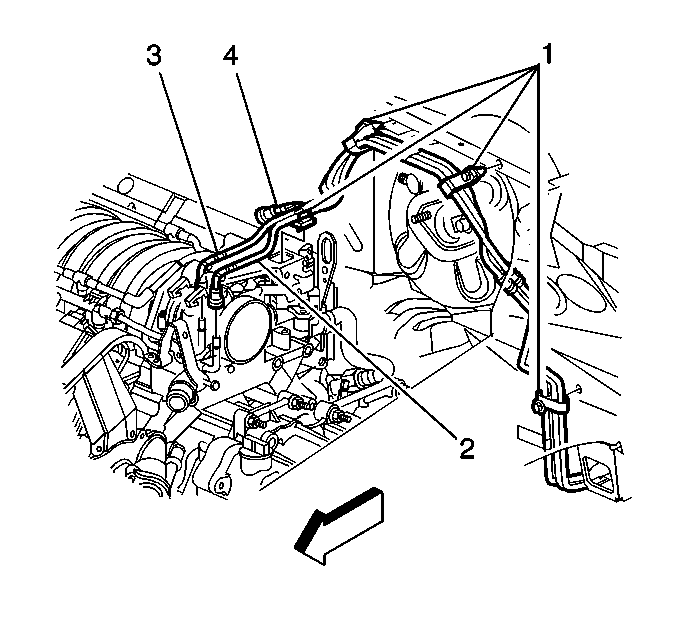
|
| Figure 21: |
EVAP Vent Solenoid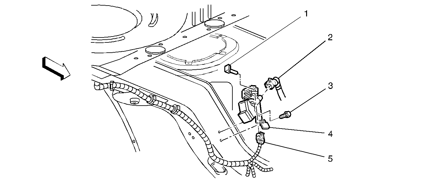
|
| Figure 22: |
Fuel Tank Pressure Sensor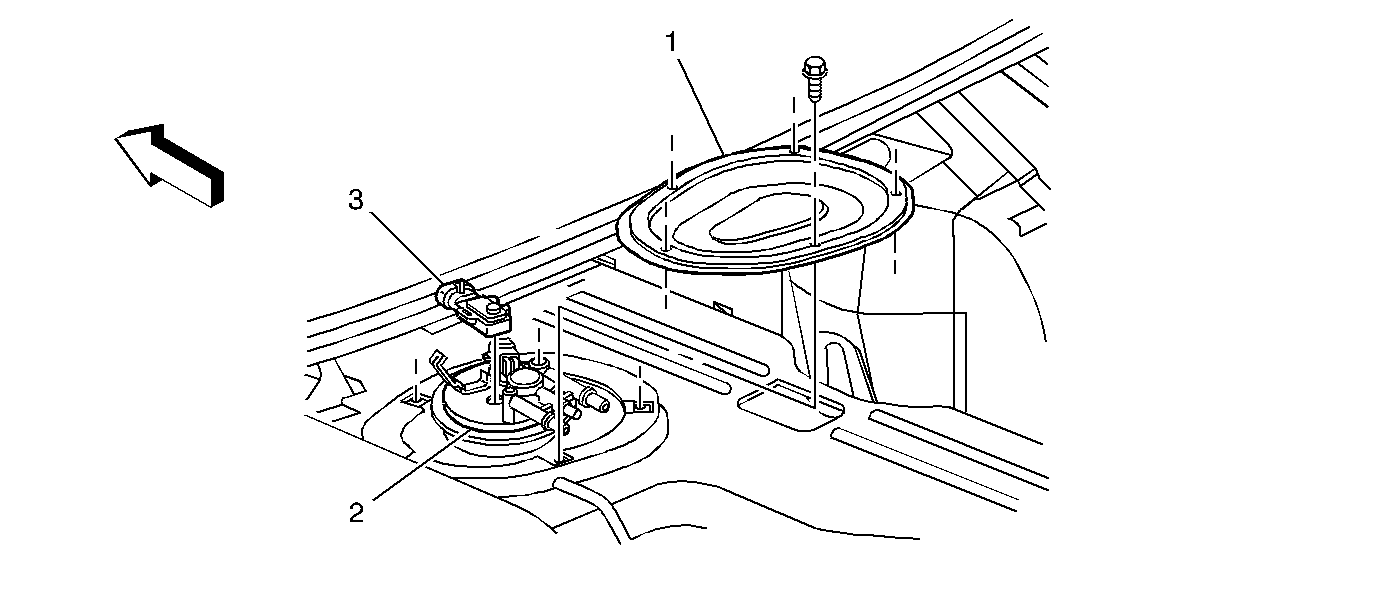
|
