Removal Procedure
CAUTION:: This system operates using fluid pressure up to 12 400 kPa (1800 psi). Some malfunctions can cause this pressure to be trapped in the system. Use caution when loosening pipe fittings on a system that does not work or personal injury can result.
Caution: Refer to Brake Fluid Irritant Caution in the Preface section.
Notice: When adding fluid to the brake master cylinder reservoir, use only Delco Supreme 11®, GM P/N 12377967 (Canadian P/N 992667), or equivalent DOT-3 brake fluid from a clean, sealed brake fluid container. The use of any type of fluid other than the recommended type of brake fluid, may cause contamination which could result in damage to the internal rubber seals and/or rubber linings of hydraulic brake system components.
Notice: Refer to Brake Fluid Effects on Paint and Electrical Components Notice in the Preface section.
- To relieve the brake system pressure, pump the brake pedal at least 8 times or until the brake pedal becomes very hard.
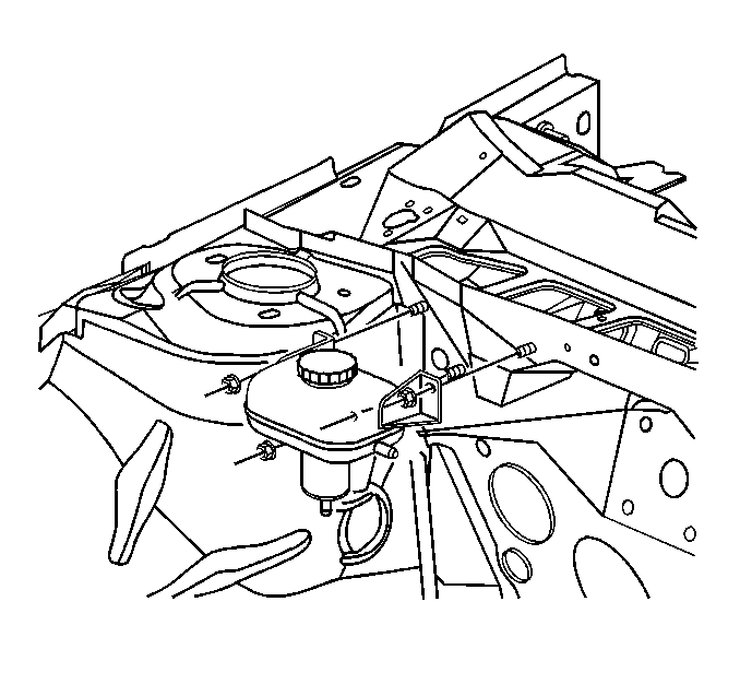
- Remove the brake fluid from the hydraulic brake booster reservoir.
- Disconnect the master cylinder fluid level sensor electrical connector.
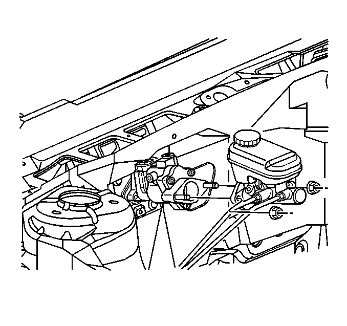
- Remove the master cylinder mounting nut.
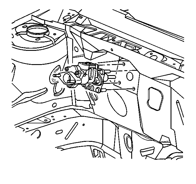
- Remove the master cylinder from the booster. Move the master cylinder forward just enough to clear the studs on the booster. This will flex the brake pipes slightly. Be careful not to bend or distort the pipes.
- Disconnect the hydraulic pressure (feed) line from the rear of the booster.
- Disconnect the hydraulic return hose clamp from the top of the booster.
- Disconnect the hydraulic return hose from the top of the booster.
- Install a rubber cap or plug to the exposed hydraulic lines to prevent fluid loss and contamination.
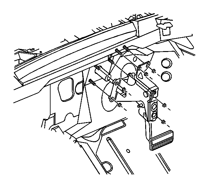
- Remove the right closeout panel. Refer to Instrument Panel Insulator Panel Replacement - Right Side in Instrument Panel, Gages and Console.
- Remove the hydraulic brake booster mounting nuts from the brake pedal assembly.
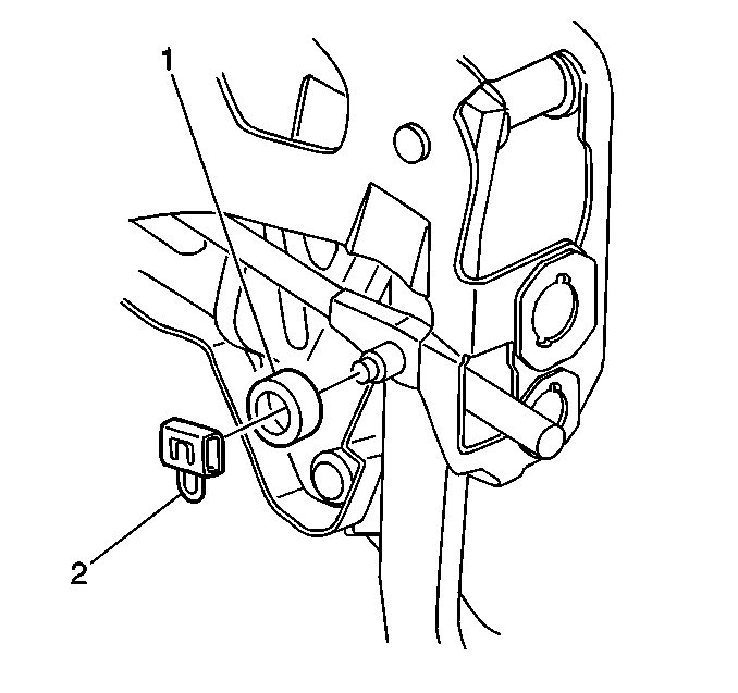
- Remove the hydraulic brake booster pushrod retainer clip (2).
- Remove the foam spacer (1) from the brake pedal clevis pin.
- Remove the hydraulic brake booster pushrod from the brake pedal clevis pin.
- Remove the hydraulic brake booster from the vehicle.
Important: Pressure must be removed from the brake system before servicing.
Installation Procedure
- Install the hydraulic brake booster to the vehicle.
- Install the hydraulic brake booster pushrod to the brake pedal clevis pin.
- Install the foam spacer (1) to the brake pedal clevis pin.
- Install the hydraulic brake booster pushrod retainer clip (2).
- Install the hydraulic brake booster mounting nuts onto the booster mounting studs.
- Install the right closeout panel. Refer to Instrument Panel Insulator Panel Replacement - Right Side in Instrument Panel, Gages and Console.
- Install the return hose to the hydraulic brake booster.
- Install the return hose clamp.
- Install the master cylinder onto the booster.
- Connect the hydraulic pressure (feed) line to the booster.
- Install the master cylinder mounting nuts.
- Fill the booster reservoir.
- Connect the fluid level sensor electrical connector.
- If the hydraulic system was opened, bleed the brake system. Refer to Hydraulic Brake System Bleeding .


Notice: Use the correct fastener in the correct location. Replacement fasteners must be the correct part number for that application. Fasteners requiring replacement or fasteners requiring the use of thread locking compound or sealant are identified in the service procedure. Do not use paints, lubricants, or corrosion inhibitors on fasteners or fastener joint surfaces unless specified. These coatings affect fastener torque and joint clamping force and may damage the fastener. Use the correct tightening sequence and specifications when installing fasteners in order to avoid damage to parts and systems.
Tighten
Tighten the hydraulic brake booster mounting nuts to 28 N·m (21 lb ft).

Tighten
Tighten the master cylinder mounting nuts to 25 N·m (18 lb ft).
