Ignition Switch Lock Cylinder Replacement RHD
Removal Procedure
Caution: Refer to SIR Caution in the Preface section.
- Disable the SIR. Refer to
SIR Disabling and Enabling
in SIR.
- Apply the parking brake.
- Disconnect the negative battery cable, in order to maintain the key code.
Refer to
Battery Negative Cable Disconnection and Connection
in Engine Electrical.
- Remove the right instrument panel (I/P) outer trim cover. Refer to
Instrument Panel Outer Trim Cover Replacement
.
- Insert the ignition key into the ignition cylinder.
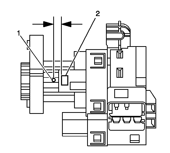
Important: A new lock cylinder housing and lock cylinder bezel will be required if the
ignition cylinder is seized or the ignition key is lost or broken.
- If the keys are unavailable or the ignition lock cylinder is seized, proceed
with the following steps:
| 6.1. | Pry the ignition lock cylinder bezel off of the ignition switch. |
| 6.3. | Disconnect the ignition switch electrical connectors. |
| 6.4. | Remove the fasteners securing the ignition switch to the I/P retainer. |
| 6.5. | Remove the ignition switch through the radio opening. |
| 6.6. | Protect the immediate work area with suitable materials such as clean
shop towels or a clean fender cover. |
| 6.7. | Locate the ignition switch lock cylinder release button (2) on
the plastic ignition switch housing. |
| 6.8. | Center punch on the rib (1) approximately 3/8 inch toward
the key entry end of the ignition lock housing. |
| 6.9. | Drill a pilot hole through the plastic housing, where the housing had
been center punched in the previous step, with a 1/8 inch drill bit. |
| 6.10. | Drill the larger hole at the pilot location, and slightly into the ignition
switch lock cylinder surface to break the release button retaining spring using a
¼ inch drill bit. |
| 6.11. | Use a magnet and remove the lock cylinder release button (2). |
| 6.12. | Grasp the ignition switch lock cylinder and remove it from the switch
housing. |
| 6.13. | Remove any plastic flash from the drilling operation. Using compressed
air, blow out the ignition switch assembly and proceed to step 10. |
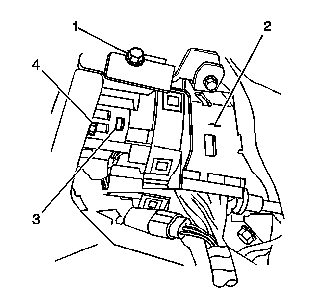
- Turn the ignition to the RUN position.
- Look through the I/P outer trim cover opening and locate the ignition
lock cylinder release button (3), located on the right lower side of the ignition
switch assembly (2).
- Using a flat-bladed tool, depress and hold the ignition lock cylinder
release button.
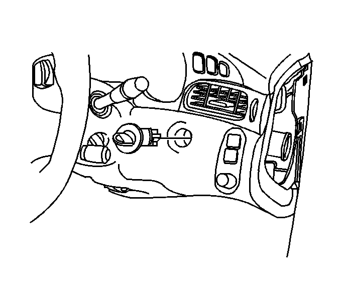
- Pull on the ignition cylinder in order to
remove the ignition lock cylinder.
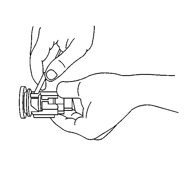
- Release the ignition cylinder lock cylinder
bezel retaining tabs.
- Remove the ignition lock cylinder bezel from the ignition lock cylinder.
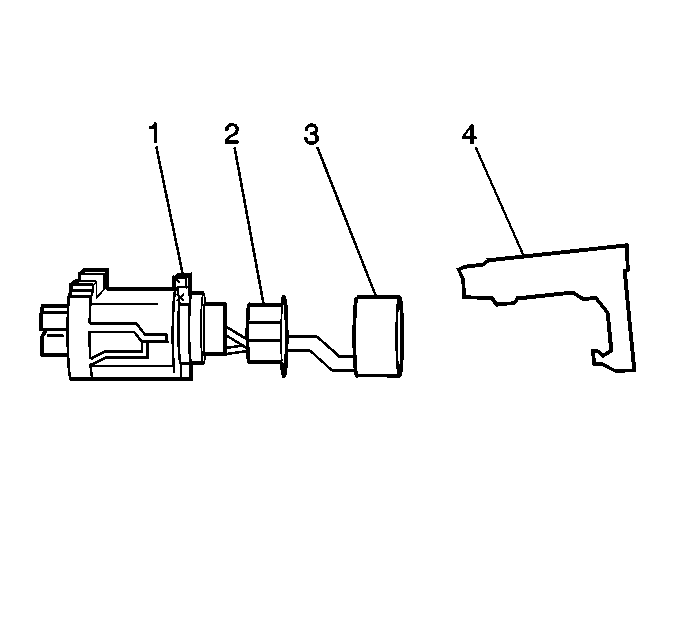
- Remove the light pipe (2) from the lock cylinder.
Slide the reader/exciter (4) off of the ignition lock cylinder.
Installation Procedure

- Slide the reader/exciter (4) onto the ignition lock cylinder.
- Install the ignition lock cylinder light pipe (2) to the ignition
cylinder.
- Install the ignition cylinder bezel to the ignition lock cylinder, and
engage the retainers.
- If the ignition lock cylinder was previously seized or the key was lost
or broken, proceed with the following steps:
| 4.1. | Turn the ignition switch to the RUN position. |
| 4.2. | Install the ignition switch to the I/P. |
| 4.3. | Connect the ignition switch electrical connectors. |
| 4.5. | Turn the new ignition lock cylinder to the RUN position. |
| 4.6. | Turn the ignition switch to the RUN position. |
| 4.7. | Push the ignition lock cylinder into the ignition switch until fully seated.
It may be necessary to slightly depress the release button as it passes by the ¼ inch
hole drilled in the switch housing. |
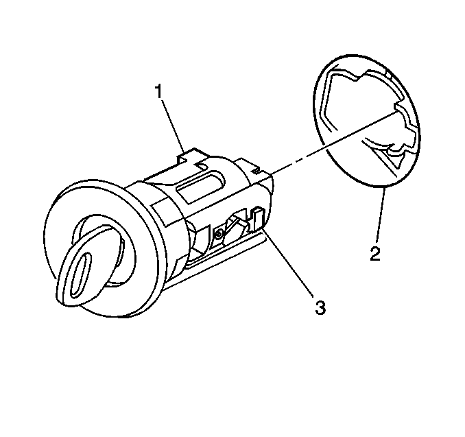
- With the key installed in the ignition lock
cylinder (1) and the cylinder in RUN, insert the ignition lock cylinder (1)
into the I/P opening (2).
The lock cylinder release button (3) will produce an audible click.
- Using light force, pull on the lock cylinder in order to ensure the lock
cylinder is engaged.
- Turn the ignition cylinder to LOCK and remove the key.
- Install the I/P outer trim cover. Refer to
Instrument Panel Outer Trim Cover Replacement
.
- Release the parking brake.
- Connect the negative battery cable. Refer to
Battery Negative Cable Disconnection and Connection
in Engine Electrical.
- Inspect the ignition switch for proper operation in all positions.
- Enable the SIR system. Refer to
SIR Disabling and Enabling
in SIR.
Ignition Switch Lock Cylinder Replacement LHD
Removal Procedure
Caution: Refer to SIR Caution in the Preface section.
- Disable the SIR. Refer to
SIR Disabling and Enabling
in SIR.
- Apply the parking brake.
- Disconnect the negative battery cable. Refer to
Battery Negative Cable Disconnection and Connection
in Engine Electrical.
- Remove the radio. Refer to
Radio Replacement
in Entertainment.
- Insert the ignition key into the ignition cylinder.

Important: A new lock cylinder housing and lock cylinder bezel will be required if the
ignition cylinder is seized or the ignition key is lost or broken.
- If the keys are broken or unavailable or the ignition lock cylinder is seized,
proceed with the following steps:
| 6.1. | Pry the ignition lock cylinder bezel off of the ignition switch. |
| 6.3. | Disconnect the ignition switch electrical connectors. |
| 6.4. | Remove the fasteners securing the ignition switch to the instrument panel
(I/P) retainer. |
| 6.5. | Remove the ignition switch through the radio opening. |
| 6.6. | Protect the immediate work area with suitable materials such as clean
shop towels or a clean fender cover. |
| 6.7. | Locate the ignition switch lock cylinder release button (2) on
the plastic ignition switch housing. |
| 6.8. | Center punch on the rib (1) approximately 3/8 inch toward
the key entry end of the ignition lock housing. |
| 6.9. | Drill a pilot hole through the plastic housing, where the housing had
been center punched in the previous step, with a 1/8 inch drill bit. |
| 6.10. | Drill the larger hole at the pilot location, and slightly into the ignition
switch lock cylinder surface to break the release button retaining spring using a
¼ inch drill bit. |
| 6.11. | Use a magnet and remove the lock cylinder release button (2). |
| 6.12. | Grasp the ignition switch lock cylinder and remove it from the switch
housing. |
| 6.13. | Remove any plastic flash from the drilling operation. Using compressed
air, blow out the ignition switch assembly and proceed to step 10. |

- Turn the ignition to the RUN position.
- Look through the I/P trim cover opening in the I/P and locate the ignition
lock cylinder release button (3) located on the right lower side of the ignition
switch assembly (2).
- Using a small flat-bladed tool depress and hold the ignition lock cylinder
release button (3).
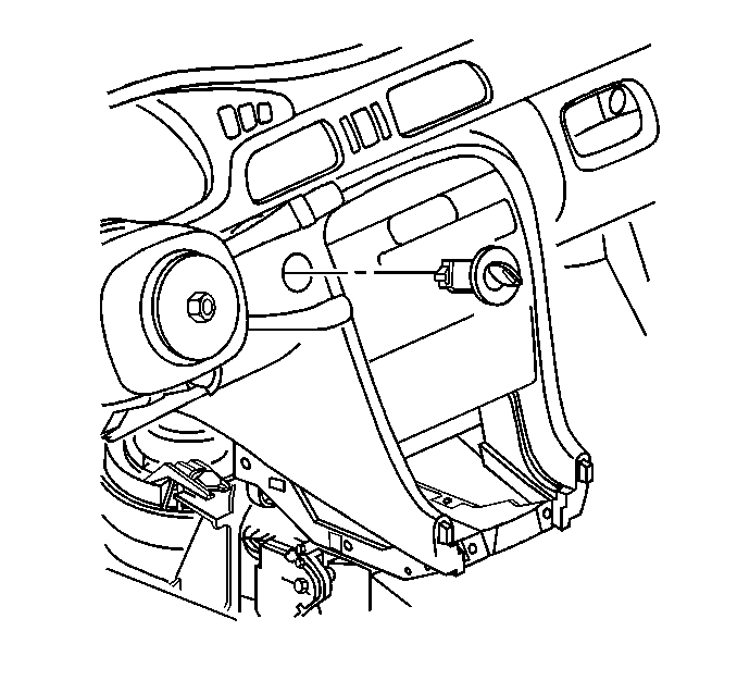
- Pull on the ignition cylinder in order to
remove the cylinder.

- Release the ignition cylinder lock cylinder
bezel retaining tabs.
- Remove the ignition lock cylinder bezel.

- Remove the light pipe (2) from the lock cylinder.
- Slide the reader/exciter (4) off of the ignition lock cylinder.
Installation Procedure

- Slide the reader/exciter (4) onto the ignition lock cylinder.
- Install the ignition lock cylinder light pipe (2) to the ignition
cylinder (1).
- Install the ignition cylinder bezel to the ignition lock cylinder, and
engage the retainers.
- If the ignition lock cylinder was previously seized, proceed with the
following steps:
| 4.1. | Turn the ignition switch to the RUN position. |
| 4.2. | Install the ignition switch to the I/P. |
| 4.3. | Connect the ignition switch electrical connectors. |
| 4.5. | Turn the new ignition lock cylinder to the RUN position. |
| 4.6. | Push the ignition lock cylinder into the ignition switch until fully seated.
It may be necessary to slightly depress the release button as it passes by the ¼ inch
hole drilled in the switch housing. |

- With the ignition key installed in the ignition
lock cylinder (1) and the ignition lock cylinder in RUN, insert the ignition
lock cylinder (1) into the I/P opening (2).
The lock cylinder release button (3) will produce an audible click, when
fully engaged.
- Using light force, pull on the lock cylinder in order to ensure the lock
cylinder is engaged.
- Turn the ignition to LOCK, then remove the ignition key.
- Install the radio. Refer to
Radio Replacement
in Entertainment.
- Release the parking brake.
- Connect the negative battery cable. Refer to
Battery Negative Cable Disconnection and Connection
in Engine Electrical.
- Inspect the ignition cylinder and switch for proper operation in all positions.
- Enable the SIR system. Refer to
SIR Disabling and Enabling
.


