Electronic Suspension Control Module Replacement F55
Removal Procedure
- Remove the rear storage compartment trim. Refer to Rear Compartment Front Trim Panel Replacement in Body Rear End.
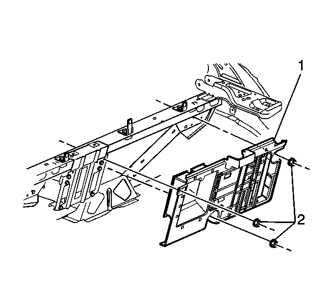
- Remove the bay board fasteners (2).
- Pull the bay board (1) away from the body and place the bay board (1) module side up in the rear compartment.
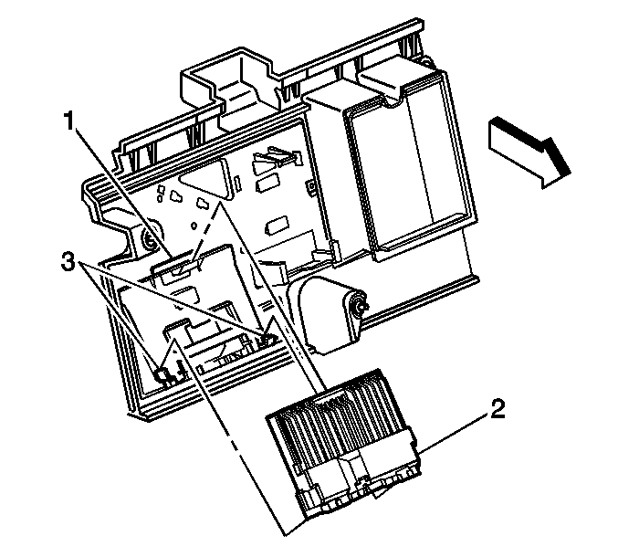
- Remove the ESC module by depressing the locking tab (1), in order to release the suspension module (2) from the bay board.
- Disconnect the electrical connectors from the ESC module.


Installation Procedure
- Connect the electrical connectors to the ESC module (2).
- Insert the ESC module (2) into the bay board tabs (3) and locking tab (1).
- Install the bay board (1) to the vehicle body.
- Install the bay board retaining nuts (2).
- Install the rear storage compartment trim. Refer to Rear Compartment Front Trim Panel Replacement in Body Rear End.
- Use a scan tool in order to perform the Bump Stop Trim Set procedure.


Notice: Use the correct fastener in the correct location. Replacement fasteners must be the correct part number for that application. Fasteners requiring replacement or fasteners requiring the use of thread locking compound or sealant are identified in the service procedure. Do not use paints, lubricants, or corrosion inhibitors on fasteners or fastener joint surfaces unless specified. These coatings affect fastener torque and joint clamping force and may damage the fastener. Use the correct tightening sequence and specifications when installing fasteners in order to avoid damage to parts and systems.
Tighten
Tighten the nuts (2) to 9 N·m (80 lb in).
ESC Module Programming
- Connect the scan tool to the data link connector DLC.
- Turn ON the ignition, with the engine OFF.
- Proceed per the instructions on the scan tool readout.
Important:
• New ECM modules must be calibrated after installation. DTC C0563 is stored
in the memory of ESC modules and will not clear until the module is calibrated. • The scan tool must have the latest chassis application program.
