GM Service Manual Online
For 1990-2009 cars only
Makes
🢒
Cadillac
🢒
2004
🢒
Seville
🢒
Accessories
🢒
Entertainment
🢒 Theft Deterrent System Schematics
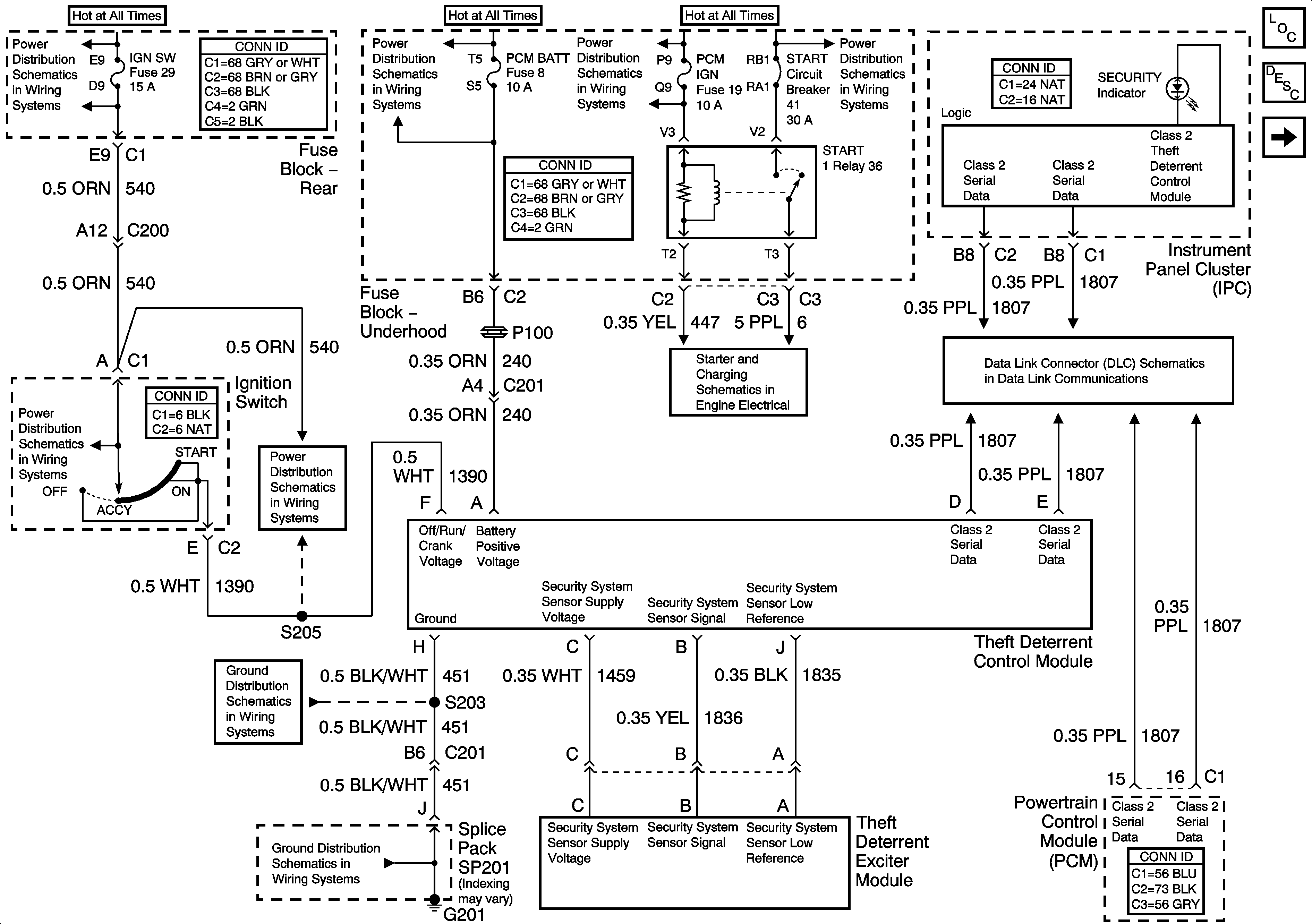
Figure
1:
Vehicle Theft Deterrent (VTD) System (LH Drive)
Master Electrical Component List
Vehicle Theft Deterrent (VTD) Description and Operation
Theft Deterrent System Schematics-Vehicle Theft Deterrent (RH Drive)
Power Distribution Schematics-Ignition Switch and Heated Seat Fuses
Power Distribution Schematics-Ignition Switch Supply
Power Distribution Schematics-ALDL, PCM Battery, I/P, ABS Fuses
Power Distribution Schematics-Battery Feed to Fuseblock Underhood
Starting and Charging Schematics-Starting Controls
Data Link Connector (DLC) Schematics-Serial Data Line (LH Drive) (1 of 2)
Ground Distribution Schematics-G201 (1 of 5)
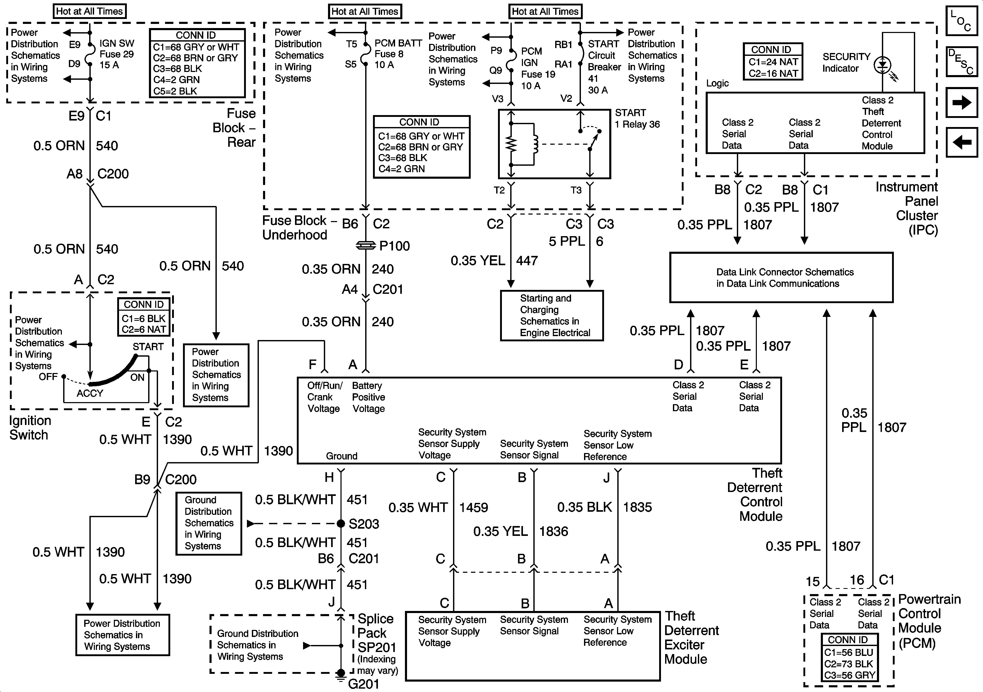
Figure
2:
Vehicle Theft Deterrent (VTD) System (RH Drive)
Master Electrical Component List
Vehicle Theft Deterrent (VTD) Description and Operation
Theft Deterrent System Schematics-Content Theft Deterrent (CTD)
Theft Deterrent System Schematics-Vehicle Theft Deterrent (LH Drive)
Power Distribution Schematics-Ignition Switch and Heated Seat Fuses
Power Distribution Schematics-Ignition Switch Supply
Power Distribution Schematics-ALDL, PCM Battery, I/P, ABS Fuses
Power Distribution Schematics-Battery Feed to Fuseblock Underhood
Starting and Charging Schematics-Starting Controls
Data Link Connector (DLC) Schematics-Serial Data Line (LH Drive) (1 of 2)
Power Distribution Schematics-Ignition Switch Supply
Ground Distribution Schematics-G201 (1 of 5)
Figure
3:
Content Theft Deterrent (CTD) System
Master Electrical Component List
Content Theft Deterrent (CTD) Description and Operation
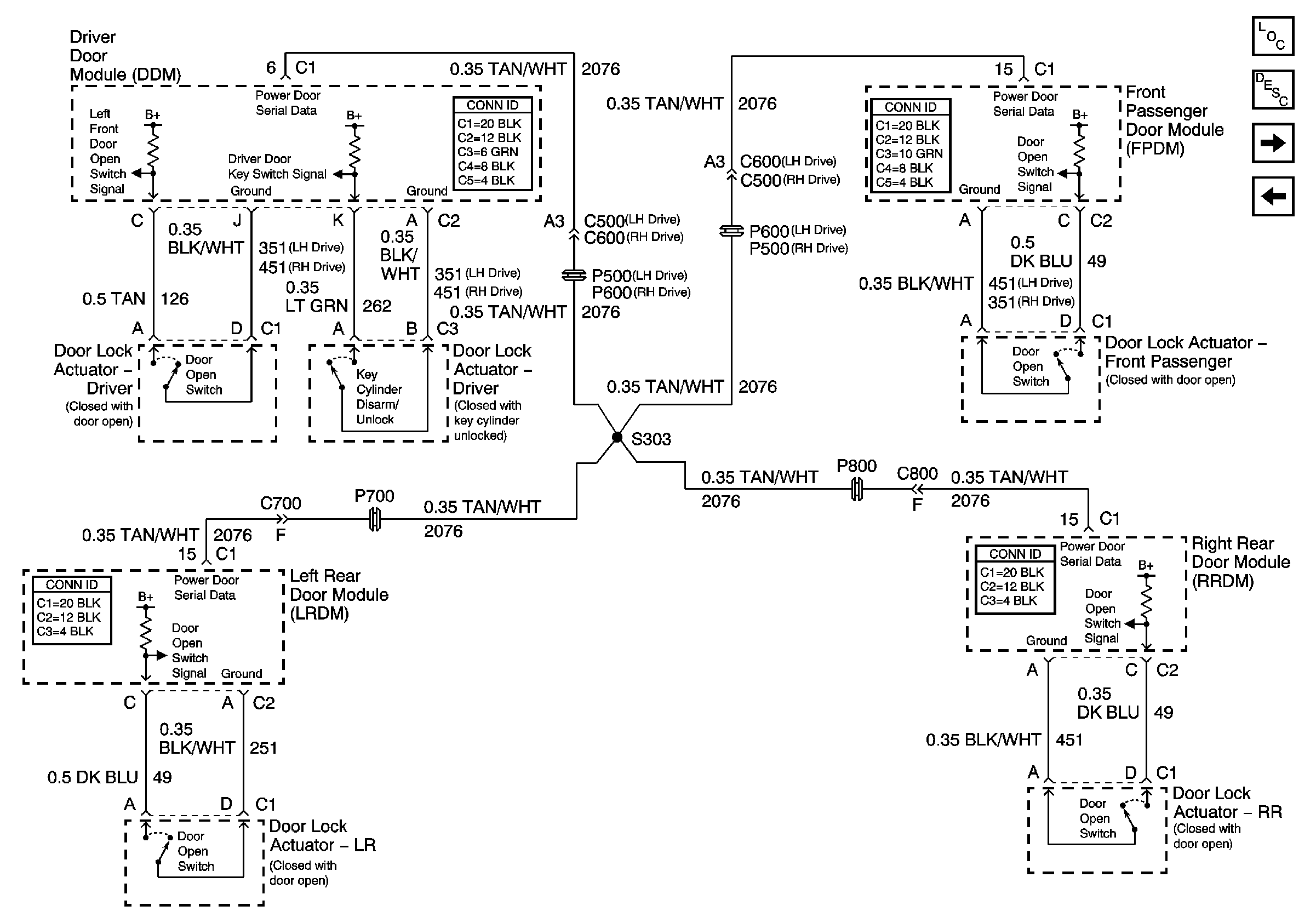
Theft Deterrent System Schematics-Class 2 and Tamper Switches
Theft Deterrent System Schematics-Vehicle Theft Deterrent (RH Drive)
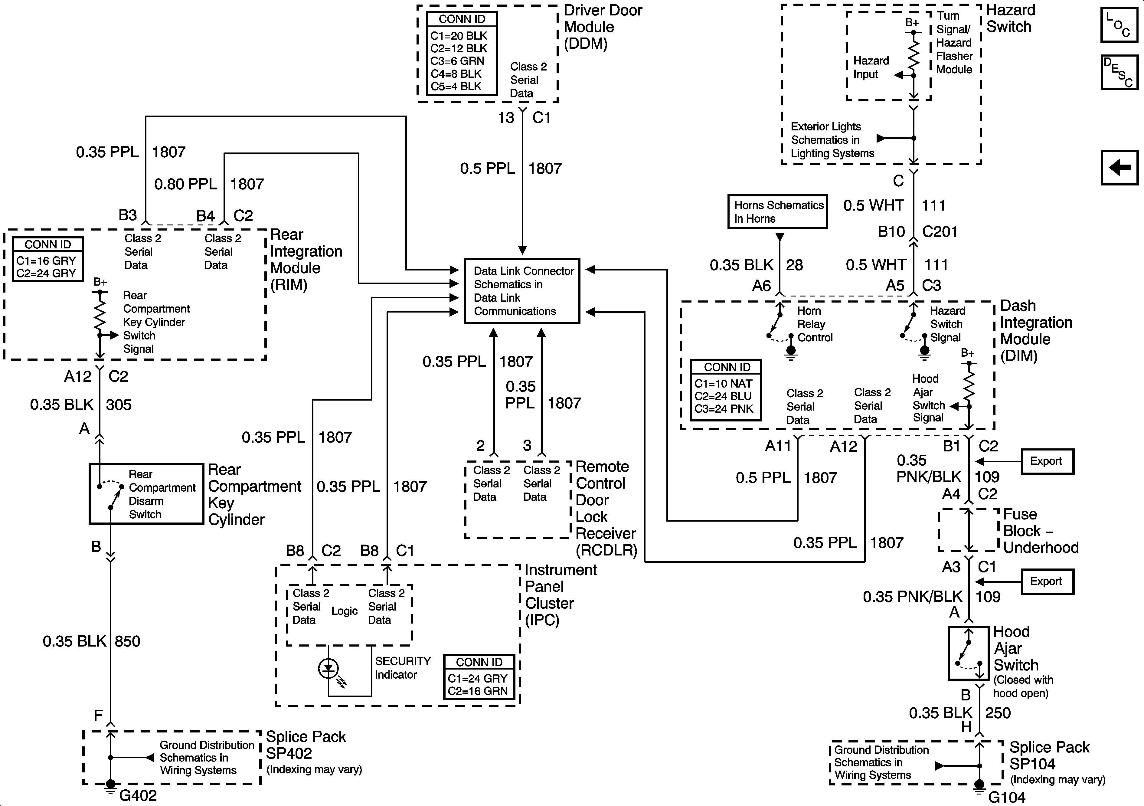
Figure
4:
Class 2 and Tamper Switches
Master Electrical Component List
Theft Systems Description and Operation
Theft Deterrent System Schematics-Content Theft Deterrent (CTD)
Exterior Lights Schematics-Hazard Switch
Horns Schematics
Data Link Connector (DLC) Schematics-Serial Data Line (LH Drive) (2 of 2)
Ground Distribution Schematics-G104
Ground Distribution Schematics-G402 (1 of 2)