Tools Required
Setting the camshaft timing is necessary whenever the camshaft drive system has been disturbed such that the alignment relationship between any chain and sprocket has been lost.
The crankshaft and camshafts are correctly timed when the crank sprocket and the intermediate shaft sprocket have their timing marks aligned and all four camshaft position actuator timing marks are perpendicular (90 degrees) to the cylinder head
deck surface and are near the top of their rotation.
- Remove the following components for access:
Important: The primary gears and chain must be properly timed prior to setting the left or right secondary camshaft timing.
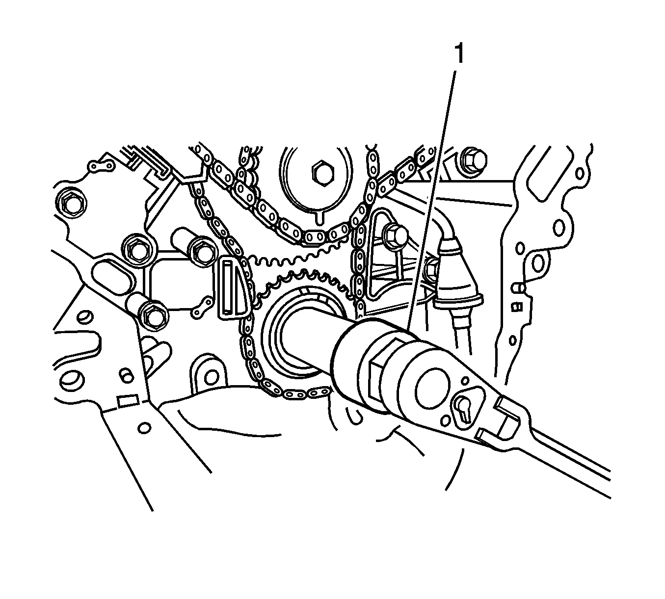
- Using the
J 39946
(1), rotate the crankshaft until:
| 2.1. | The primary timing gear alignment mark is at the top of its position, |
| 2.2. | The crankshaft keyway is approximately at the 1 o'clock position, |
| 2.3. | The intermediate sprocket timing mark is at the bottom of its rotation (adjacent to the crank gear timing mark) as shown. |
Timing the primary timing gears ensures that the #1 cylinder piston (Bank 1 right front cylinder)
is at TDC beginning its power stroke event. If this condition can not be accomplished while rotating the crankshaft, remove the primary gears and chain and realign the primary timing marks. Refer to
Primary Camshaft Drive Chain and Sprockets Replacement
.
Caution: Refer to Camshaft Holding Tool Caution in the Preface section.
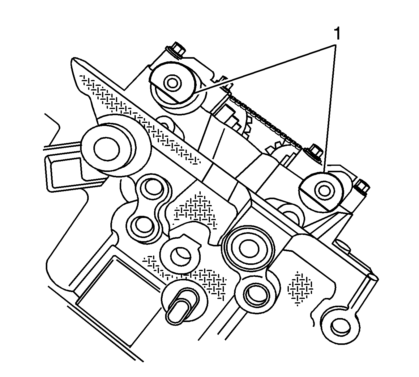
- The rear of each camshaft has a flat-machined surface which mates with special camshaft holding tool
EN 46328
(1) to prevent valve spring tension from rotating the camshafts unexpectedly. When each
bank of camshafts is properly positioned for secondary timing alignment the intake and exhaust camshafts flat spots will be parallel to each other.
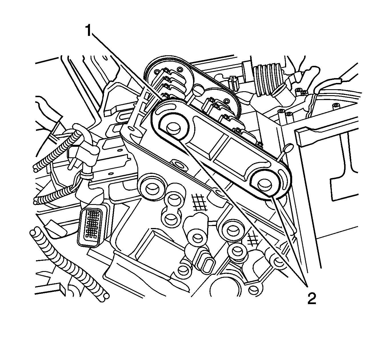
- This permits the
J 39946
to be installed (2), and prevents the camshafts
from being rotated by valve spring tension.
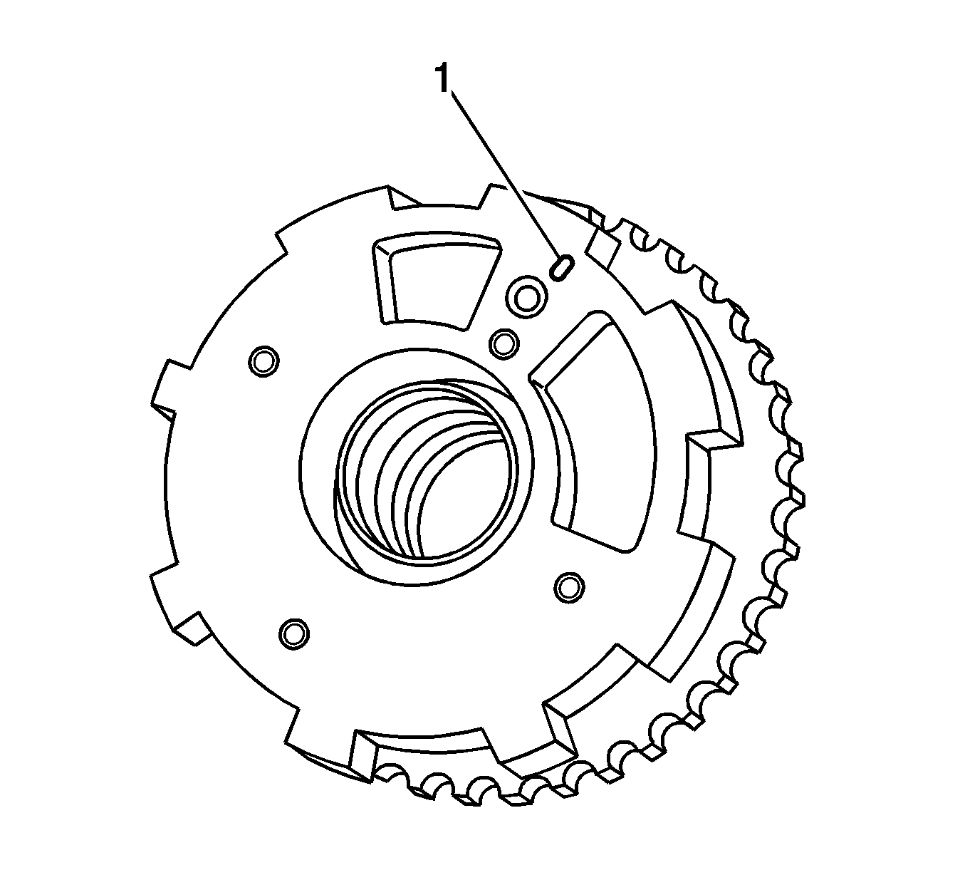
- Position both Bank 2 (left) camshafts with the position actuator timing marks (1) near the top of its rotation perpendicular
(90 degrees) to the cylinder head deck surface as shown.
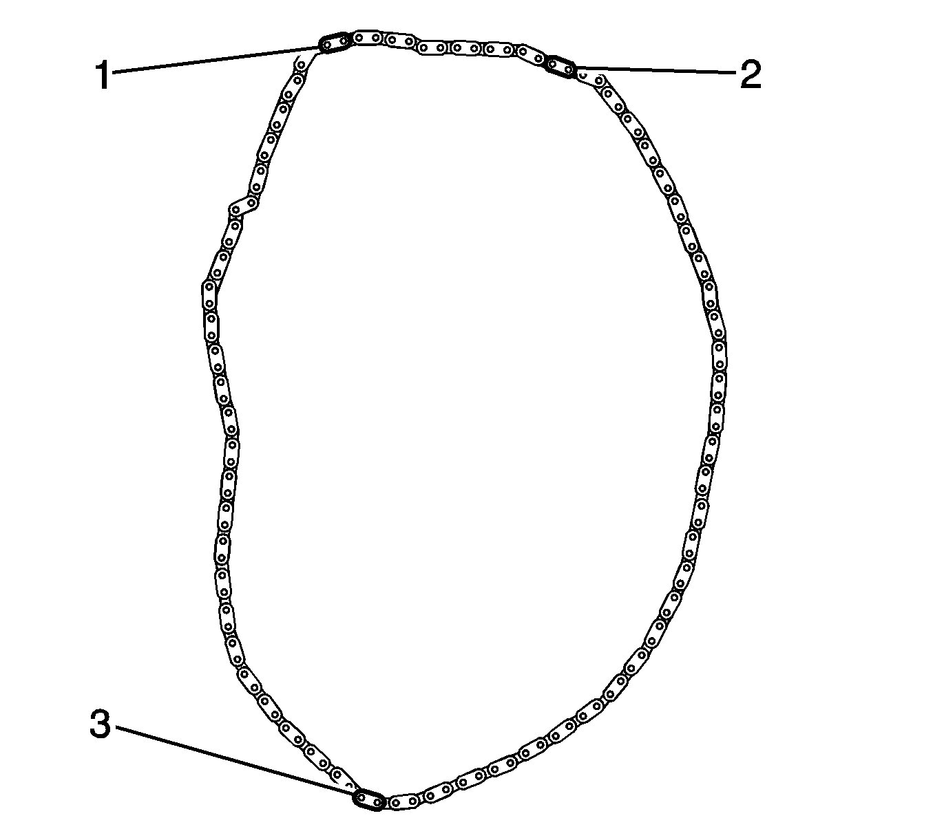
- Each secondary timing chain has three black links (1, 2, 3) that aid in timing the secondary camshaft position actuators to the intermediate
sprockets. These black links DO NOT need to be used when servicing only one of the secondary timing chain or actuator assemblies. A time-saving alternative is to match mark each chain link adjacent to the camshaft actuator timing marks and an intermediate sprocket
tooth with a paint stick prior to disassembly.
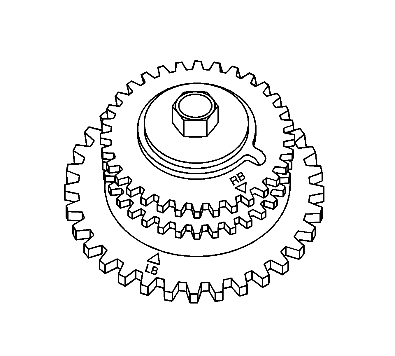
- The intermediate sprocket has a timing mark identified by the letters left bank (LB) and a triangle. The triangle point aligns with a black link on the
secondary timing chain.

- Assemble the left secondary timing chain to the left intake camshaft position actuator, and the left intermediate timing sprocket, with the alignment marks
adjacent to the black chain links (1, 3) as indicated above.
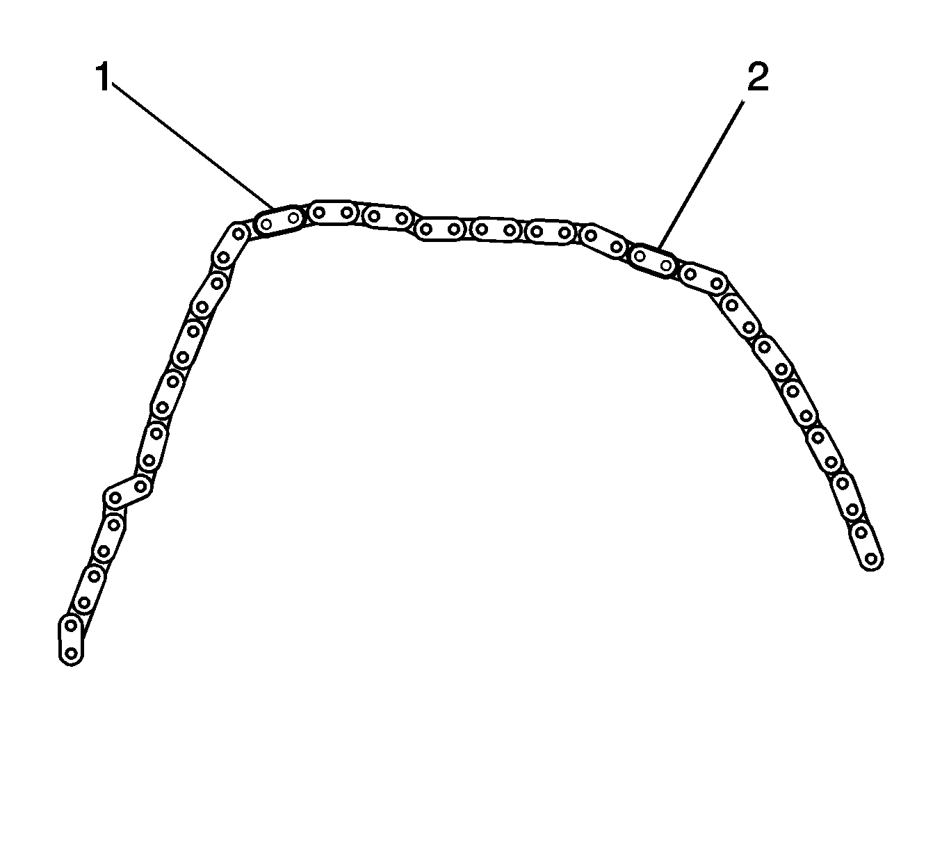
- Assemble the left exhaust camshaft position actuator with its timing mark aligned with the black link (2) in the secondary timing chain as shown.
Refer to
Camshaft Position Actuator Replacement - Bank 2 (Left Side) Exhaust
.
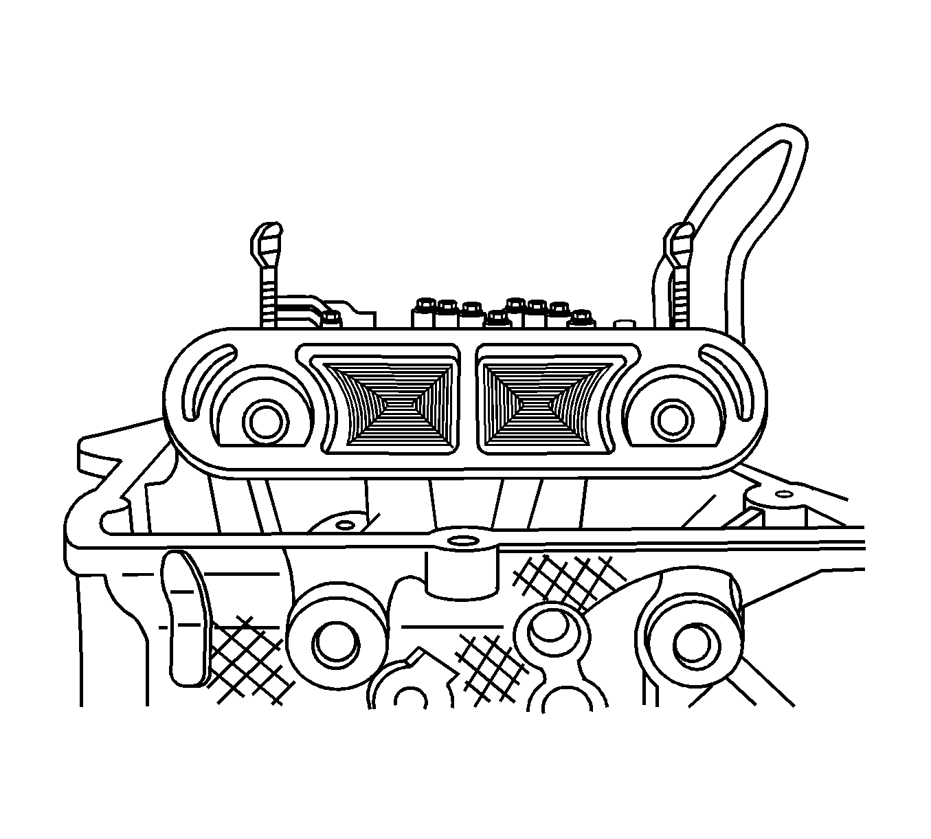
- The 2 flat-machined surfaces at the rear of each camshaft will be facing downward and parallel to each other. Install the
J 39946
over the ends of the camshafts as shown, and rotate both thumbscrews down until they contact the camshafts.
Important: The Bank 2 (left) camshaft position actuators and intermediate timing sprocket must be properly timed prior to setting the timing on the Bank 1 (right) camshafts.
- With the Bank 1 (right) intake camshaft position actuator assembled to the camshaft, rotate the actuator so that its timing mark is perpendicular (90 degrees) to the cylinder head deck surface and is near the top of its rotation.

- The intermediate timing gear outer most sprocket timing mark is labeled with the letters right bank (RB). The triangle point is timed to a black link on
the right secondary timing chain.
- Align the intermediate right bank sprocket timing mark with the black link on the secondary chain.

- Align the black link (2) of the secondary timing chain to the timing mark on the right intake camshaft position actuator.
- Align the timing mark of the Bank 1 (right) exhaust camshaft position actuator to the black link (1) on the secondary timing chain and assemble the actuator on the exhaust camshaft as shown. Refer to
Camshaft Position Actuator Replacement - Bank 1 (Right Side) Exhaust
.
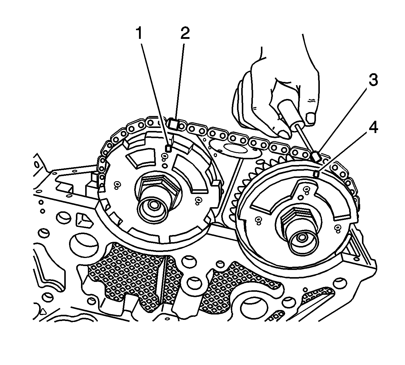
Important: Once the black secondary timing chain links (2, 3) are aligned with the timing marks of the camshaft position actuators (1, 4) and intermediate sprockets, the crankshaft would need to be rotated
126 revolutions for all of the black secondary chain links and timing marks to come into alignment again. For this reason it is NOT NECESSARY to have the black secondary chain links aligned with the timing marks when servicing only one of the secondary
timing assemblies.
- Proper alignment is achieved by marking a chain link and sprocket gear tooth with a paint stick prior to disassembling the components.


