Transmission Fluid Cooler Hose/Pipe Replacement Front
Removal Procedure
- Recover the refrigerant from the A/C system. Refer to Refrigerant Recovery and Recharging in Heating , Ventilation and Air Conditioning.
- Remove the upper radiator support. Refer to Radiator Support Replacement in Engine Cooling.
- Disconnect the upper transmission oil cooler (TOC) line from the radiator. Refer to Transmission Fluid Cooler Hose/Pipe Quick-Connect Fitting Disconnection and Connection .
- Remove the A/C compressor. Refer to Air Conditioning Compressor Replacement .
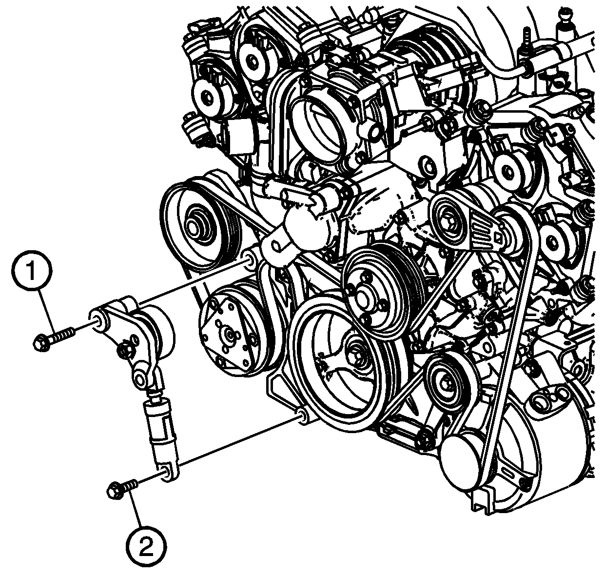
- Remove the accessory belt tensioner top bolt (1).
- Remove the accessory belt tensioner lower bolt (2).
- Remove the accessory belt tensioner.
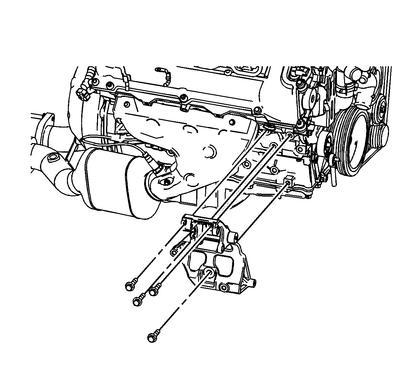
- Remove the A/C compressor and power steering pump bracket bolts.
- Remove the A/C compressor and power steering pump bracket.
- Raise the engine cradle back into position.
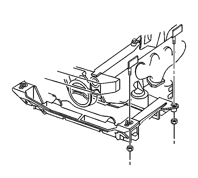
- Install the RH cradle mounting nuts.
- Remove the support jacks from beneath the vehicle.
- Lower the vehicle.
- Install the engine support fixture. Refer to Engine Support Fixture in Engine Mechanical - 4.6L.
- Raise the vehicle approximately 0.61 m (2.0 ft) off the ground.
- Support the engine cradle with a jack stands.
- Remove the RH cradle mounting nuts.
- Lower the RH engine cradle assembly approximately 0.375 in (51.0 mm)
- Remove the RH engine mount upper nut.
- Remove the RH engine mount lower nut
- Remove the RH engine mount bracket bolts.
- Using the J 28467-B , raise the engine assembly approximately 0.75 in (19.0 mm) to remove RH engine mount bracket
- Remove the RH engine mount bracket.
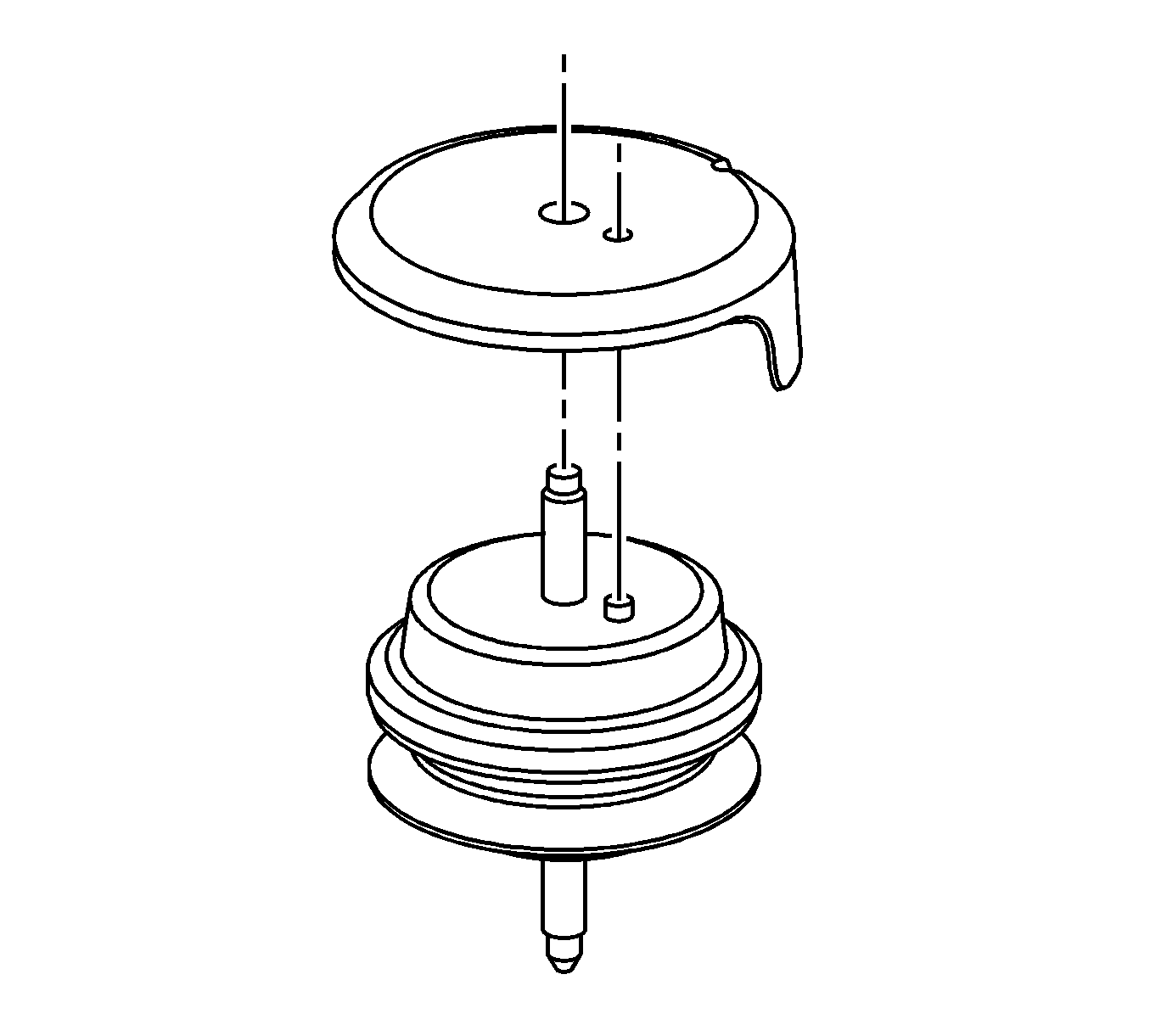
- Remove the RH engine mount heat shield from the engine mount.
- Remove the RH engine mount.
- Raise and support the vehicle.
- Remove the TOC line to oil pan retaining nuts.
- Remove the TOC line to oil pan retaining clips.
- Disconnect the upper and lower TOC retainer clip.
- Disconnect the front TOC lines from the rear TOC line set. Refer to Transmission Fluid Cooler Hose/Pipe Quick-Connect Fitting Disconnection and Connection .
- Disconnect the oil level sensor electrical connector.
- Remove the TOC lines.
Important: It is not necessary to fully tighten the cradle nuts to specification at this time. They will be removed again at a later step. Tighten until the cradle mounting nuts contacts the engine cradle.
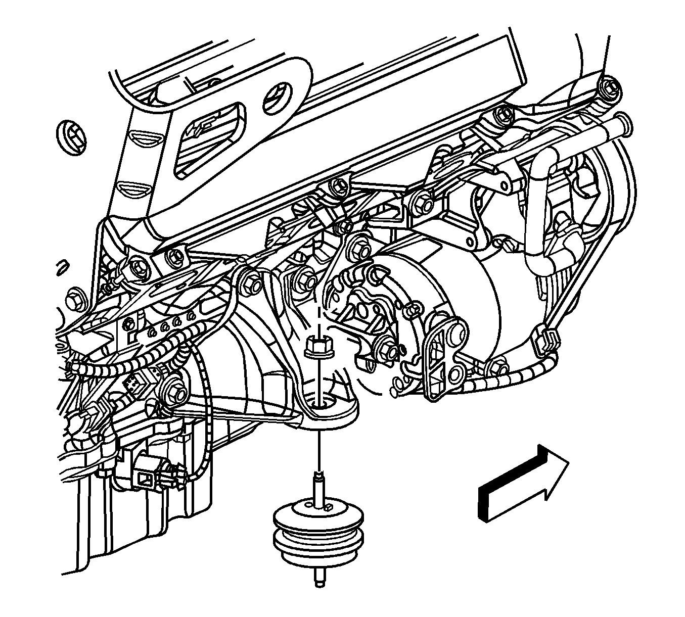
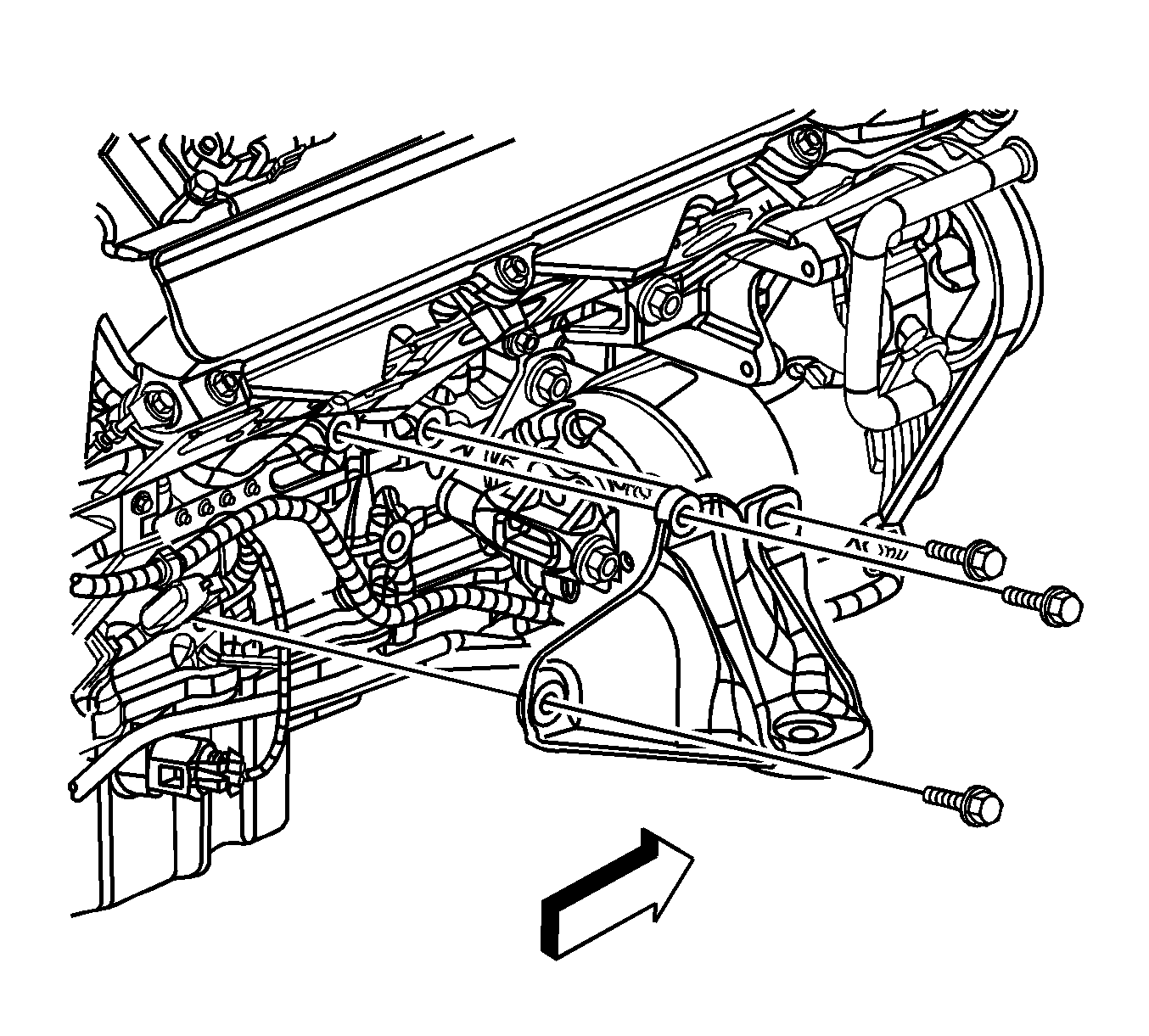
Important: It is necessary to elevate the engine assembly slightly to allow clearance for the RH engine mount bracket removal.
Installation Procedure
- Install the TOC lines.
- Connect the oil level sensor electrical connector.
- Connect the front TOC lines to the rear TOC line set. Refer to Transmission Fluid Cooler Hose/Pipe Quick-Connect Fitting Disconnection and Connection .
- Connect the upper and lower TOC retainer clip.
- Install the TOC line to oil pan retaining clips.
- Install the TOC line to oil pan retaining nuts.
- Lower the vehicle.
- Install the RH engine mount.
- Install the RH engine mount heat shield to the engine mount.
- Install the RH engine mount bracket.
- Install the RH engine mount bracket bolts.
- Using the J 28467-B , lower the engine assembly into position.
- Install the RH engine mount lower nut
- Install the RH engine mount upper nut.
- Install the A/C compressor and power steering pump bracket.
- Install the A/C compressor and power steering pump bracket bolts.
- Install the accessory belt tensioner.
- Install the accessory belt tensioner lower bolt (2).
- Install the accessory belt tensioner top bolt (1).
- Install the A/C compressor. Refer to Air Conditioning Compressor Replacement .
- Connect the upper transmission oil cooler (TOC) line to the radiator. Refer to Transmission Fluid Cooler Hose/Pipe Quick-Connect Fitting Disconnection and Connection .
- Install the upper radiator support. Refer to Radiator Support Replacement in Engine Cooling.
- Evacuate and recharge the A/C system. Refer to Refrigerant Recovery and Recharging in Heating , Ventilation and Air Conditioning.
- Check the transmission fluid level, add if necessary. Refer to Transmission Fluid Check .

Notice: Use the correct fastener in the correct location. Replacement fasteners must be the correct part number for that application. Fasteners requiring replacement or fasteners requiring the use of thread locking compound or sealant are identified in the service procedure. Do not use paints, lubricants, or corrosion inhibitors on fasteners or fastener joint surfaces unless specified. These coatings affect fastener torque and joint clamping force and may damage the fastener. Use the correct tightening sequence and specifications when installing fasteners in order to avoid damage to parts and systems.
Tighten
Tighten the nuts to 12 N·m (9 lb ft).
Important: When installing the engine mount, be sure to have the locating dowel in the correct position.


Tighten
Tighten the bolts to 58 N·m (43 lb ft).
Tighten
Tighten the nut to 58 N·m (43 lb ft).

Tighten
Tighten the nut to 58 N·m (43 lb ft).

Tighten
Tighten the bolts to 50 N·m (37 lb ft).
Tighten
Tighten the bolt to 25 N·m (18 lb ft).
Tighten
Tighten the bolt to 25 N·m (18 lb ft).

Transmission Fluid Cooler Hose/Pipe Replacement Rear
Removal Procedure
- Raise and suitably support the vehicle. Refer to Lifting and Jacking the Vehicle in General Information.
- Remove the driveline tunnel closeout panel. Refer to Floor Panel Tunnel Panel Reinforcement Replacement in Propeller Shaft.
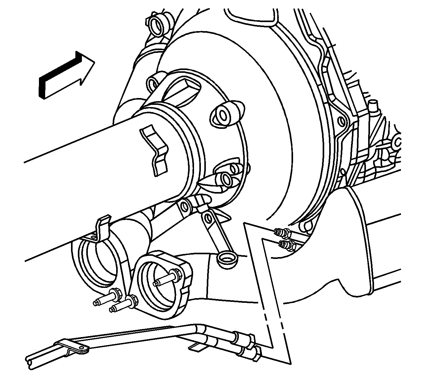
- Disconnect the front transmission oil cooler (TOC) inlet and outlet lines from the rear TOC inlet and outlet lines. Refer to Transmission Fluid Cooler Hose/Pipe Quick-Connect Fitting Disconnection and Connection .
- Remove the TOC block fitting bolt from the transmission housing.
- Rotate the TOC block fitting to unsecure the upper TOC pipe.
- Disconnect the upper and lower TOC pipes from the transmission.
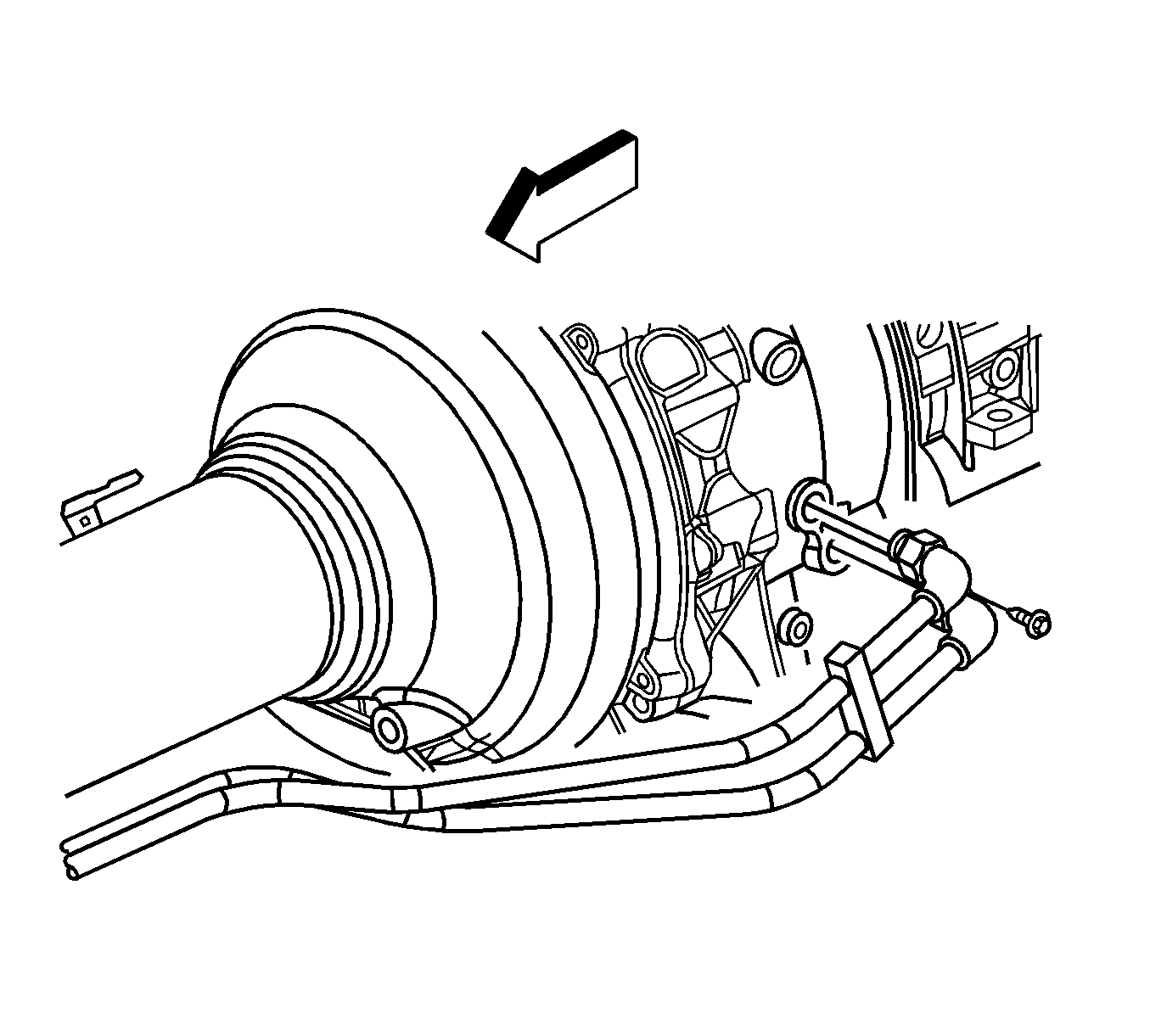
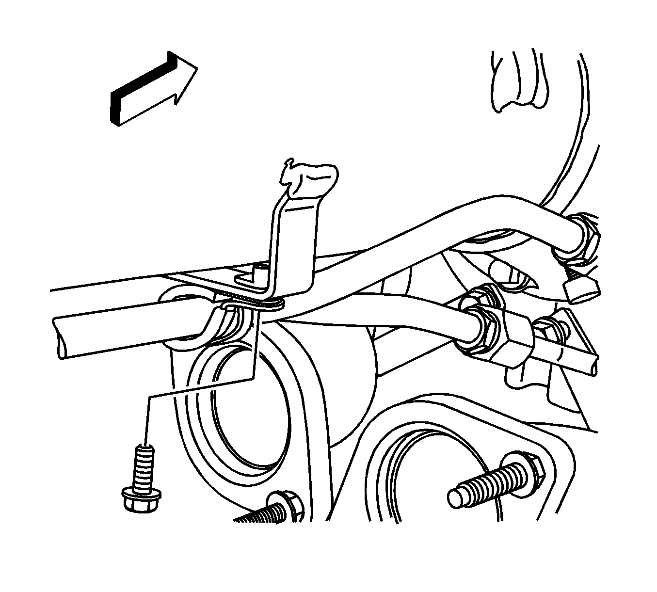
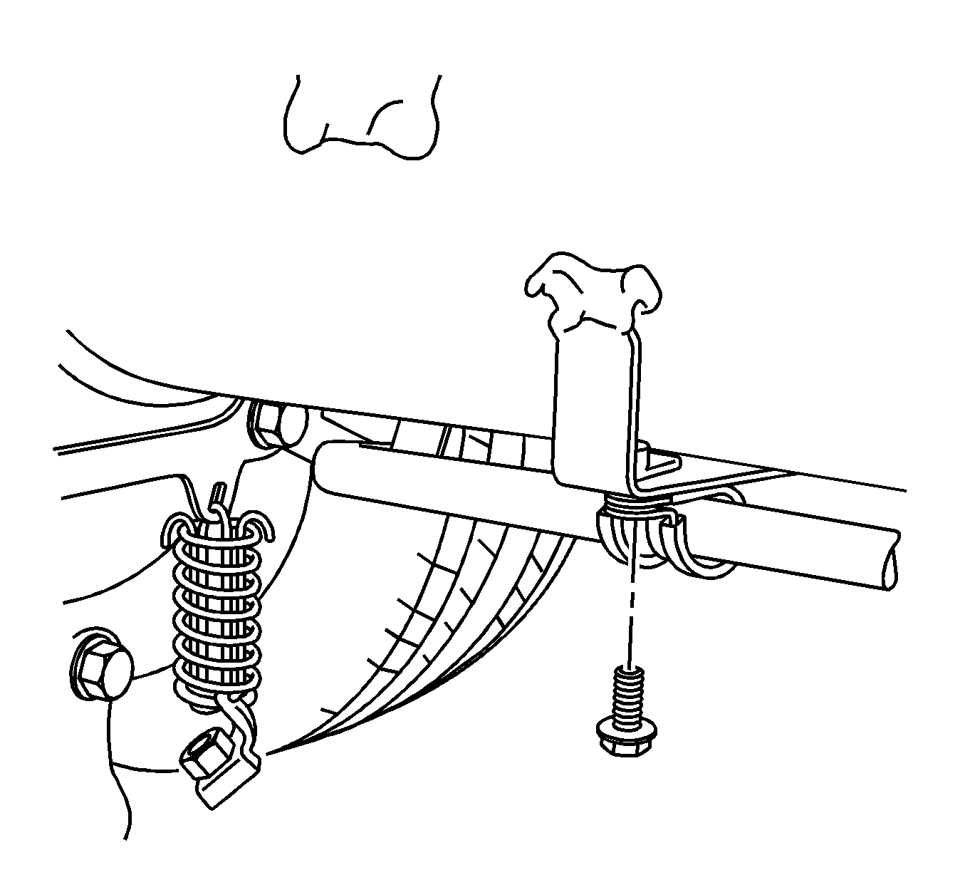
- Remove the forward TOC pipe bracket bolt.
- Remove the forward TOC pipe bracket.
- Remove the rear TOC pipe bracket bolt.
- Remove the rear TOC pipe bracket.
- Remove the TOC pipes from the vehicle.

Important:
• The front transmission oil cooler (TOC) inlet and outlet lines connect
to the rear TOC inlet and outlet lines near the engine starter motor. • Cap or plug the open TOC pipes immediately to prevent system contamination.
Cap or plug the open TOC pipes.
Cap or plug the TOC pipes and transmission fittings to prevent system contamination.
Installation Procedure
- Install the TOC pipes into position.
- Install the rear TOC pipe bracket.
- Install the rear TOC pipe bracket bolt.
- Install the forward TOC pipe bracket.
- Install the forward TOC pipe bracket bolt.
- Remove caps or plugs from the TOC pipes and transmission fittings.
- Connect the upper and lower TOC pipes to the transmission.
- Rotate the TOC block fitting to secure the upper TOC pipe.
- Install the TOC block fitting bolt to the transmission housing.
- Remove the caps or plugs from the TOC pipes.
- Connect the front TOC inlet and outlet lines to the rear TOC inlet and outlet lines. Refer to Transmission Fluid Cooler Hose/Pipe Quick-Connect Fitting Disconnection and Connection .
- Install the driveline tunnel closeout panel. Refer to Floor Panel Tunnel Panel Reinforcement Replacement in Propeller Shaft.
- Lower the vehicle.
- Check the transmission fluid level, add fluid if necessary. Refer to Transmission Fluid Check .
Notice: Use the correct fastener in the correct location. Replacement fasteners must be the correct part number for that application. Fasteners requiring replacement or fasteners requiring the use of thread locking compound or sealant are identified in the service procedure. Do not use paints, lubricants, or corrosion inhibitors on fasteners or fastener joint surfaces unless specified. These coatings affect fastener torque and joint clamping force and may damage the fastener. Use the correct tightening sequence and specifications when installing fasteners in order to avoid damage to parts and systems.

Tighten
Tighten the bolt to 12 N·m(9 lb ft).

Tighten
Tighten the bolt to 12 N·m(9 lb ft).

Tighten
Tighten the bolt to 25 N·m(18 lb ft).

