Removal Procedure
Notice: Always connect or disconnect the wiring harness connector from the EBCM/EBTCM with the ignition switch in the OFF position. Failure to observe this precaution could result in damage to the EBCM/EBTCM.
Important:
• The ignition switch must be placed in OFF mode ONLY, before disconnecting the negative battery cable during this procedure. If the ignition switch is accidentally placed into ignition ON engine OFF mode, the control modules will be activated and
disconnecting the negative battery cable will cause various DTCs to be set. Refer to
Keyless Entry System Description and Operation
in Keyless Entry. • After the ignition switch is placed into OFF mode, a waiting period of 2 minutes must be observed to allow the high-speed LAN control modules to deactivate before disconnecting or connecting the negative battery cable during this procedure.
If the waiting period is not observed, one or more of these control modules may still be active, this will cause various DTCs to be set.
- Place the ignition switch into OFF mode . Do NOT place the ignition switch into ignition ON engine OFF mode.
- Wait for a minimum of 2 minutes to allow the high-speed LAN control modules to deactivate.
- Disconnect the negative battery cable. Refer to Battery Negative Cable Disconnection and Connection in Engine Electrical.
- Thoroughly clean the electronic brake control module (EBCM) to brake pressure modulator valve (BPMV) area of any dirt or contaminants.
- Raise and support the vehicle. Refer to Lifting and Jacking the Vehicle in General Information.
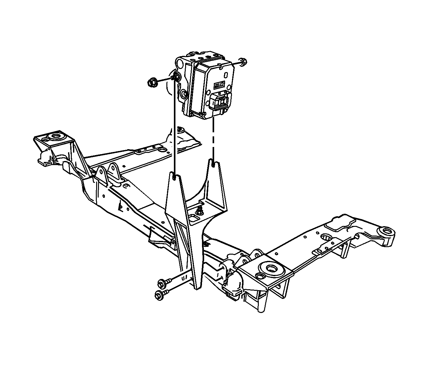
- Remove the two BPMV bracket-to-crossmember mounting bolts to improve access to the EBCM and connector.
- Support the ABS modulator assembly.
- Disconnect the electrical connector from the brake fluid pressure sensor.
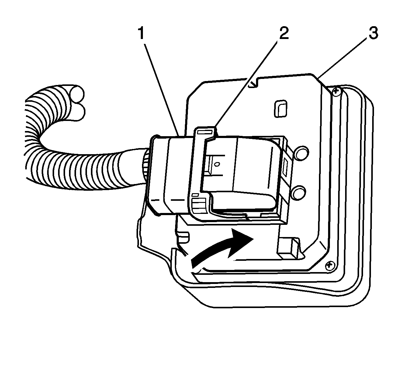
- Depress the lock tab and release the cam (2) to disconnect the electrical connector from the EBCM (3).
- Remove the 4 EBCM-to-BPMV retaining bolts.
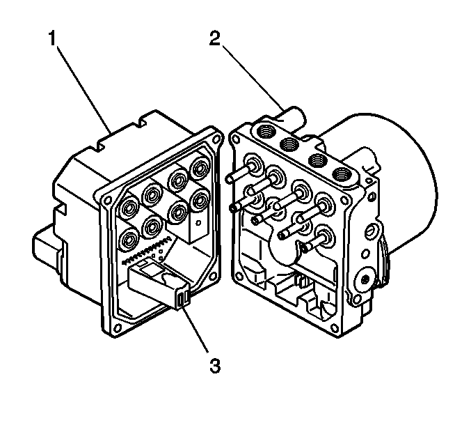
- Separate the EBCM (1) from the BPMV (2) by carefully pulling apart.


Installation Procedure
- Clean the sealing surface of the BPMV with denatured alcohol, or equivalent, and a clean shop cloth.
- Ensure the motor connector (3) is in place on the EBCM (1).
- Install the EBCM to the BPMV. Use care when aligning the EBCM (1) to the BPMV electrical terminals (2).
- Install the 4 EBCM-to-BPMV retaining bolts. Tighten the bolts in a criss-cross pattern.
- Connect the electrical connector to the EBCM (3). Ensure the cam (2) is secured by the lock tab.
- Connect the electrical connector to the brake fluid pressure sensor.
- Install the two BPMV bracket-to-crossmember mounting bolts.
- Lower the vehicle.
- Connect the negative battery cable. Refer to Battery Negative Cable Disconnection and Connection in Engine Electrical.
- If a new EBCM was installed, the EBCM must be programmed. Refer to Service Programming System (SPS) in Programming and Setup.
- Perform the Diagnostic System Check - Vehicle in Vehicle DTC Information.

Notice: Refer to Fastener Notice in the Preface section.
Tighten
Tighten the bolts to 5 N·m (44 lb in).


Tighten
Tighten the bolts to 27 N·m (20 lb ft).
