Tools Required
| • | J 39946
Crankshaft Socket - 4.0L and 4.6L |
Removal Procedure
- Remove the left intake camshaft actuator. Refer to
Camshaft Position Actuator Replacement - Bank 2 (Left Side) Intake
.
- Remove the left exhaust camshaft actuator. Refer to
Camshaft Position Actuator Replacement - Bank 2 (Left Side) Exhaust
.
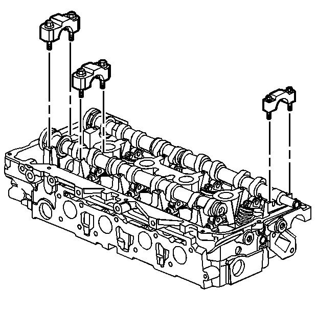
- Alternately loosen the camshaft bearing cap bolts a few turns at a time until all valve spring pressure has been released.
- Remove the camshaft bearing caps.
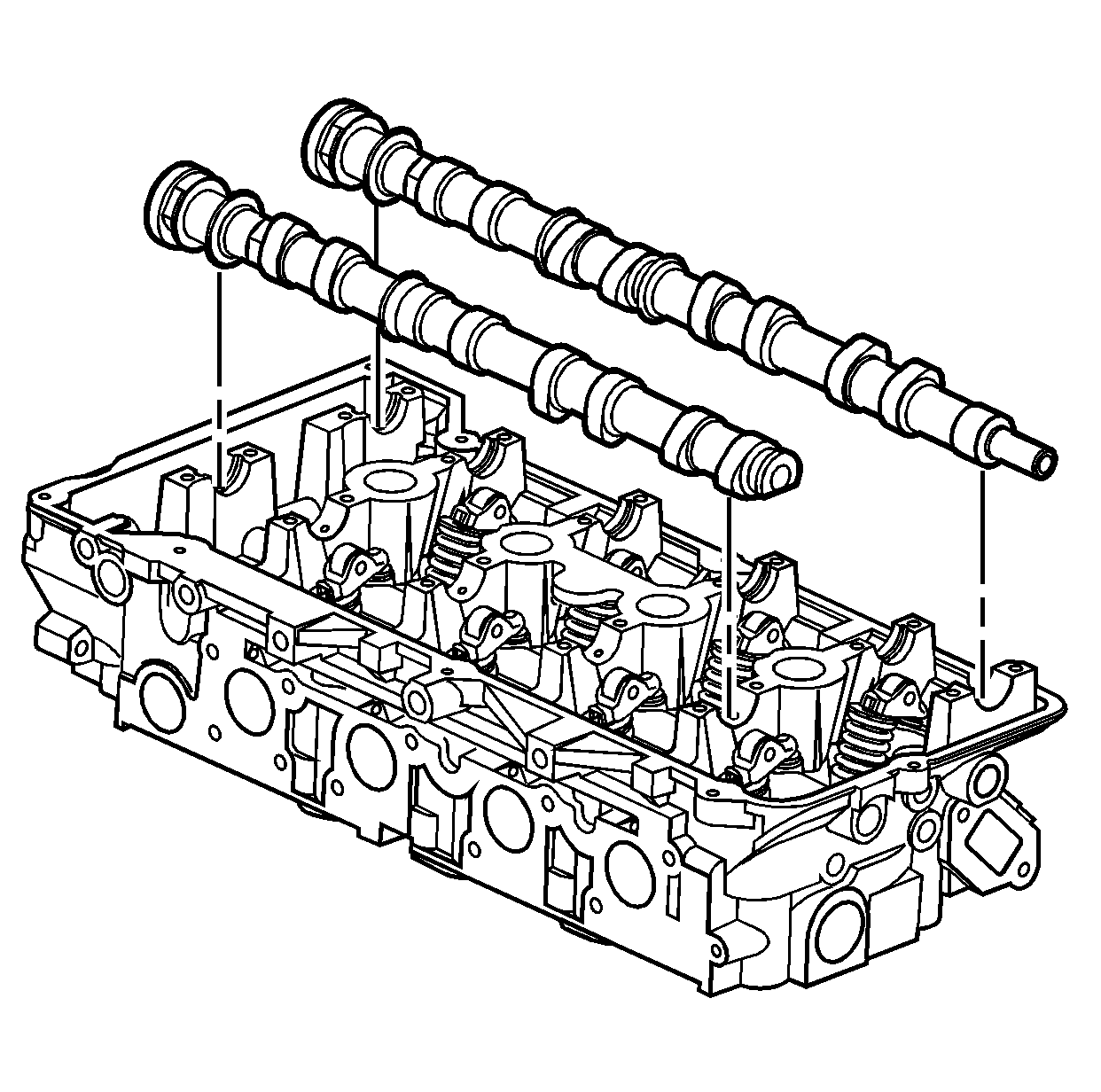
- Remove the camshafts.
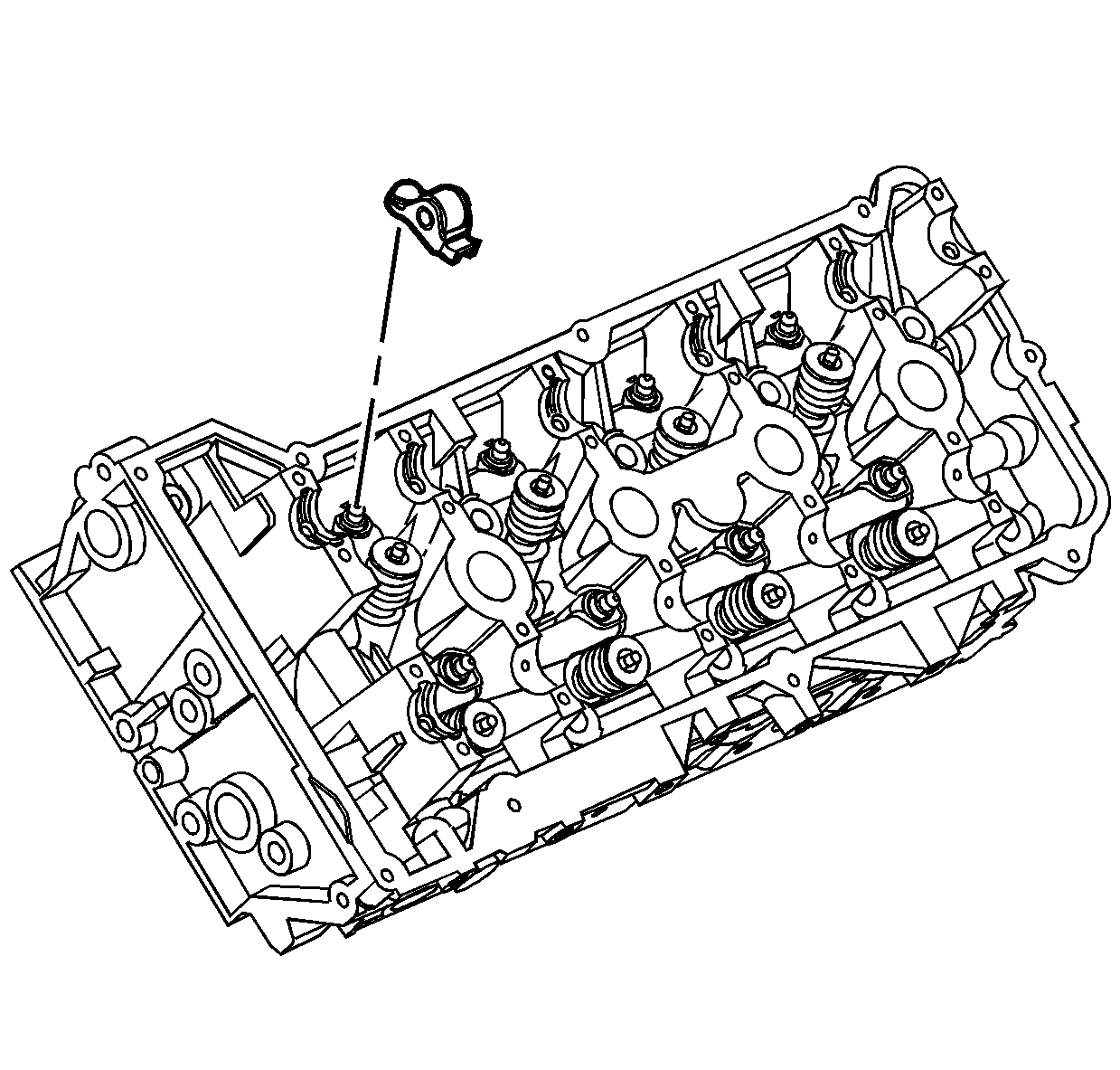
- Remove the camshaft followers.
- Clean and inspect the camshafts. Refer to
Camshaft Cleaning and Inspection
.
Installation Procedure
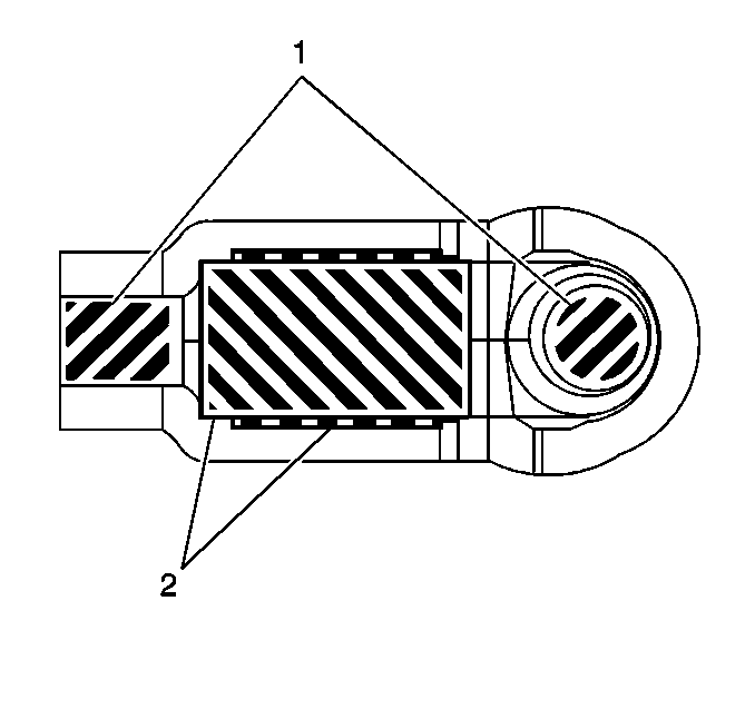
- Apply a liberal amount of lubricant to the roller pivot pocket (2) and valve slot areas (1) of the camshaft followers. Refer to
Adhesives, Fluids, Lubricants, and Sealers
for the correct part number.
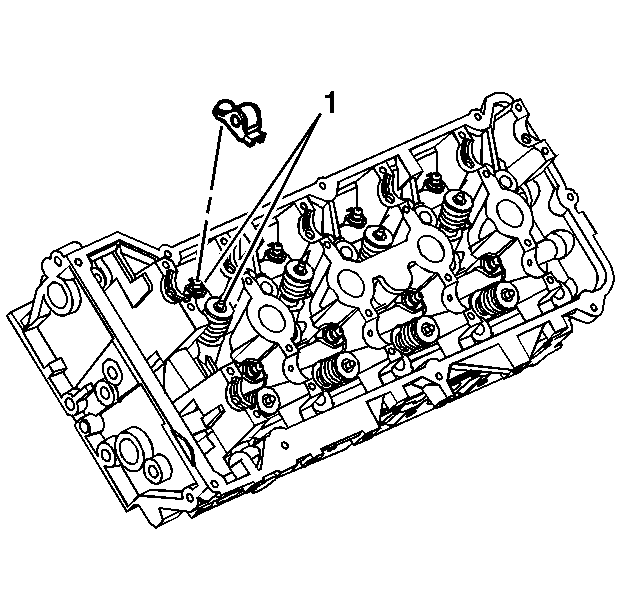
Important: The follower must be positioned squarely on the valve tip so that the full width of the roller will completely contact the camshaft lobe. If the followers are being reused you must put them back in their original location.
- Place the camshaft followers in position on the valve tip and the stationary hydraulic lash adjusters (SHLA) (1). The rounded head of the follower goes on the SHLA, while the flat end goes on the valve tip.
- Clean the camshaft carriers with a clean, lint-free cloth.
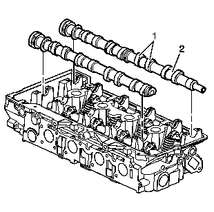
- Apply a liberal amount of lubricant to the camshaft carriers, camshaft lobes (1) and the camshaft journals (2).
Refer to
Adhesives, Fluids, Lubricants, and Sealers
for the correct part number.
- Place the camshaft in the camshaft carriers with the camshaft sprocket drive pins near the top of their rotation and the camshaft lobes in a neutral position. The camshafts can be identified by a stamping near the rear journal. For example, L-EXH
is defined as left bank exhaust.
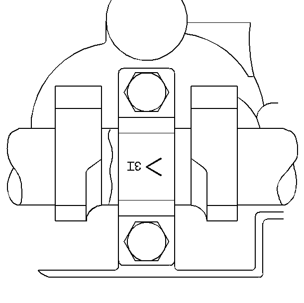
- Observe the markings on the camshaft bearing caps. Each camshaft bearing cap is marked in order to identify its location. The markings
have the following meanings:
| • | The arrow should point to the front of the engine. |
| • | The number indicates the position from the front of the engine. |
| • | The "E" indicates the exhaust camshaft. |
| • | The "I" indicates the Intake camshaft. |
- Apply a liberal amount of lubricant to the camshaft bearing caps. Refer to
Adhesives, Fluids, Lubricants, and Sealers
for the correct part number.

- Install the camshaft bearing caps according to the identification marks.
Notice: Refer to Fastener Notice in the Preface section.
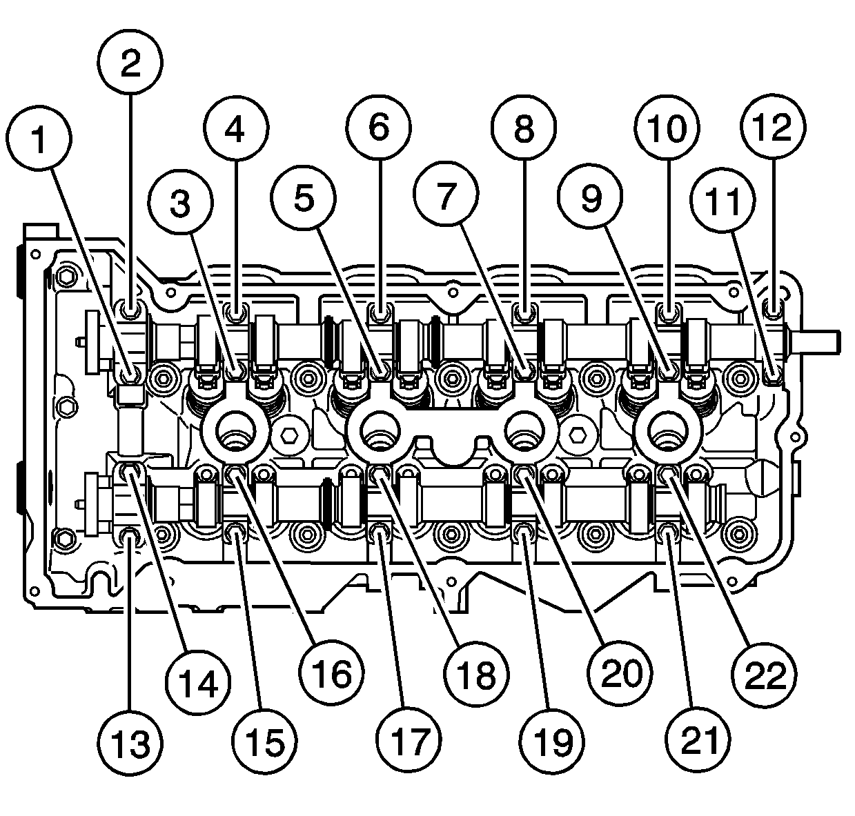
- Install the camshaft bearing cap bolts in sequence.
Tighten
- Alternately hand tighten the camshaft bearing cap bolts a few turns at a time until all caps are fully seated.
- Tighten the camshaft bearing cap bolts to 5 N·m (44 lb in).
- Tighten the camshaft bearing cap bolts an additional 30 degrees using the
J 45059
.
- Align the camshafts.
Caution: Refer to Camshaft Holding Tool Caution in the Preface section.
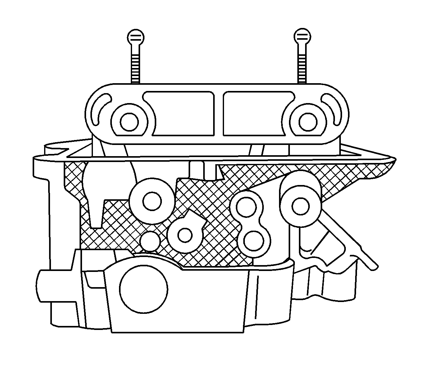
- Install the
EN 46328
over the camshafts.
- Install the left exhaust camshaft actuator. Refer to
Camshaft Position Actuator Replacement - Bank 2 (Left Side) Exhaust
.
- Install the left intake camshaft actuator. Refer to
Camshaft Position Actuator Replacement - Bank 2 (Left Side) Intake
.


