GM Service Manual Online
For 1990-2009 cars only
Makes
🢒
Cadillac
🢒
2005
🢒
XLR
🢒
Vehicle Control Systems
🢒
Vehicle DTC Information
🢒 Antilock Brake System Schematics
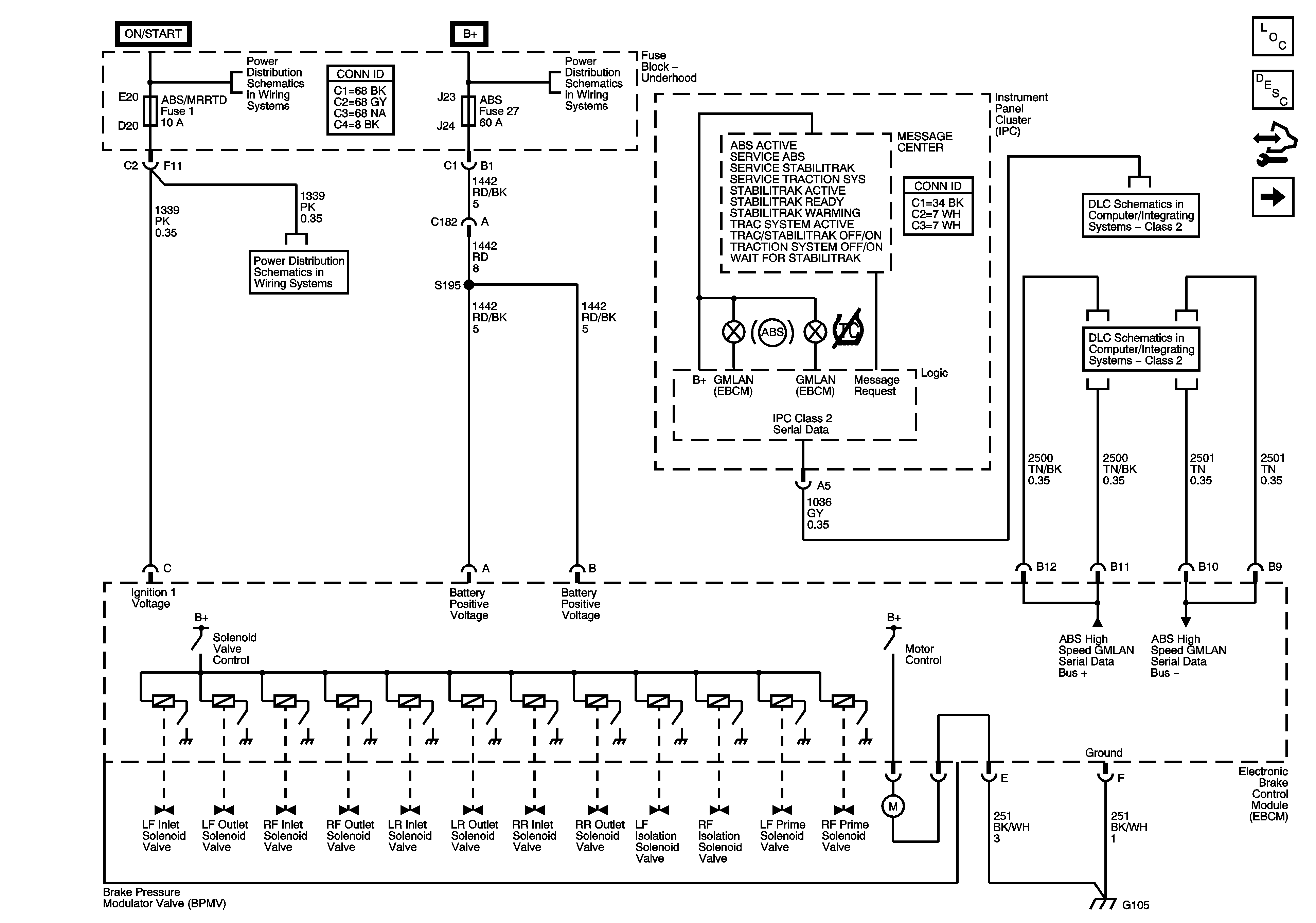
Figure
1:
Ground, Indicators, Messages, and Power
Master Electrical Component List
ABS Description and Operation
Control Module References
Wheel Speed Sensors
Fuse Block - Underhood Bussing
BCM Fuses - ECM. GMLAN Devices, RPA/H/C SEAT and SDM/PSIR SW, Fuse Block Underhood Fuses - ABS/MRRTD, and ACC/TCM
DLC - Class 2
GMLAN
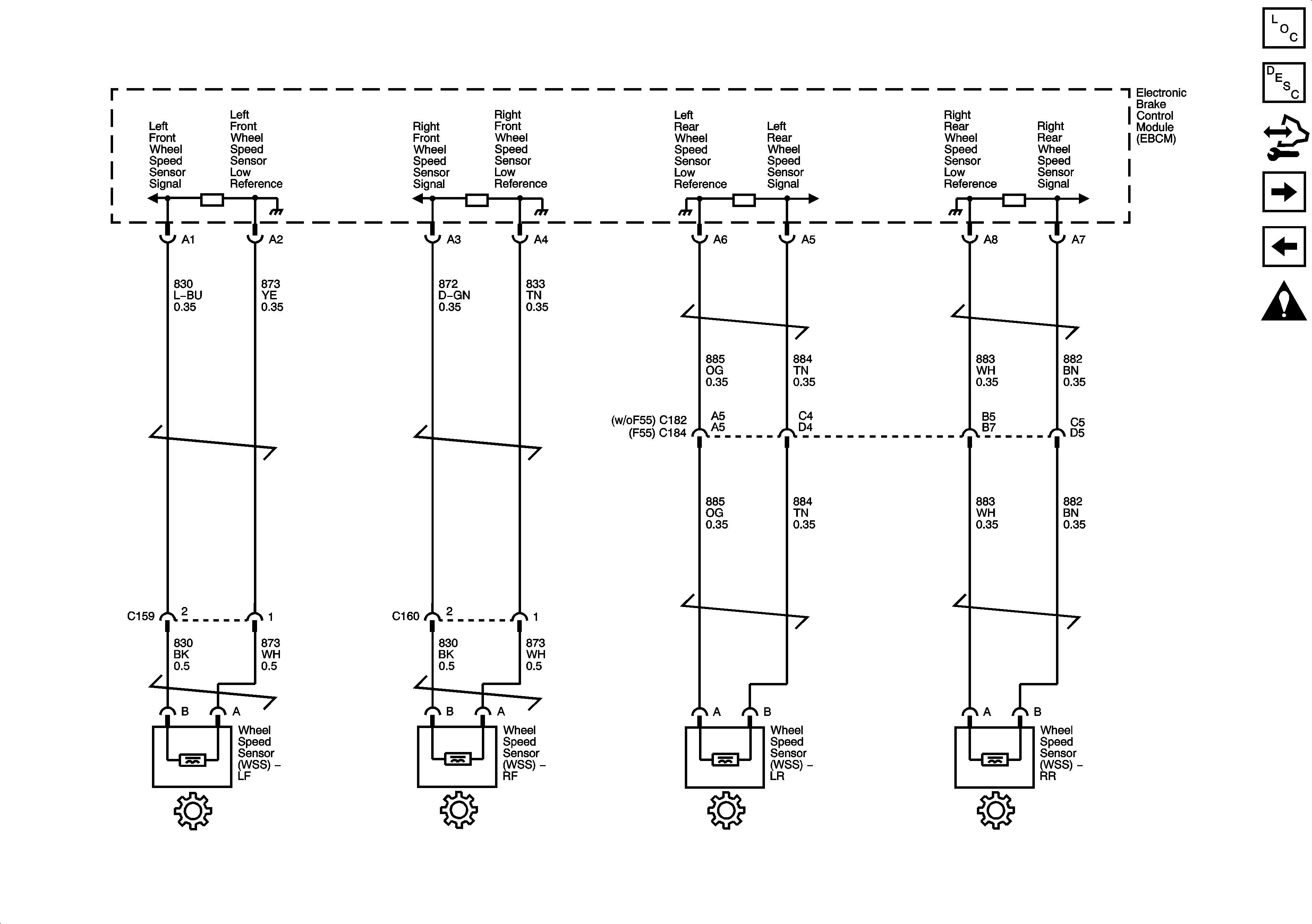
Figure
2:
Wheel Speed Sensors
Master Electrical Component List
ABS Description and Operation
Control Module References
Brake Pedal Signal and Traction Control Switch
Ground, Indicators, Messages and Power
Antilock Brake System Schematic Icons
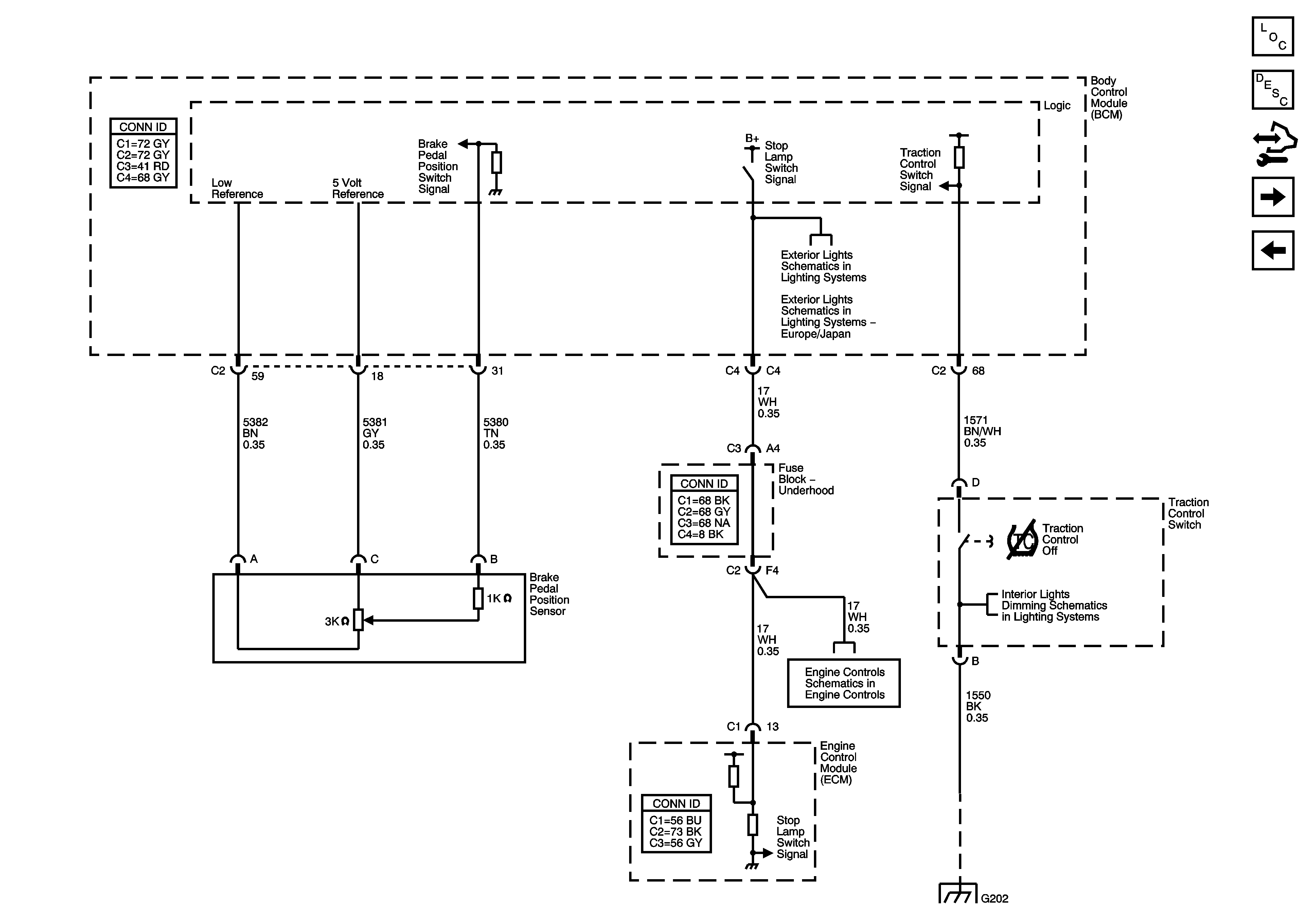
Figure
3:
Brake Pedal Signal and Traction Control Switch
Master Electrical Component List
ABS Description and Operation
Control Module References
Stability Control Sensors
Wheel Speed Sensors
Stop Lamps - Europe and Japan
Engine Data Sensors - Pressure, Temperature, MAF, VSS and Brake Travel
DLC, HVAC Control Module, Radio and Switches
G202 - 1 of 2
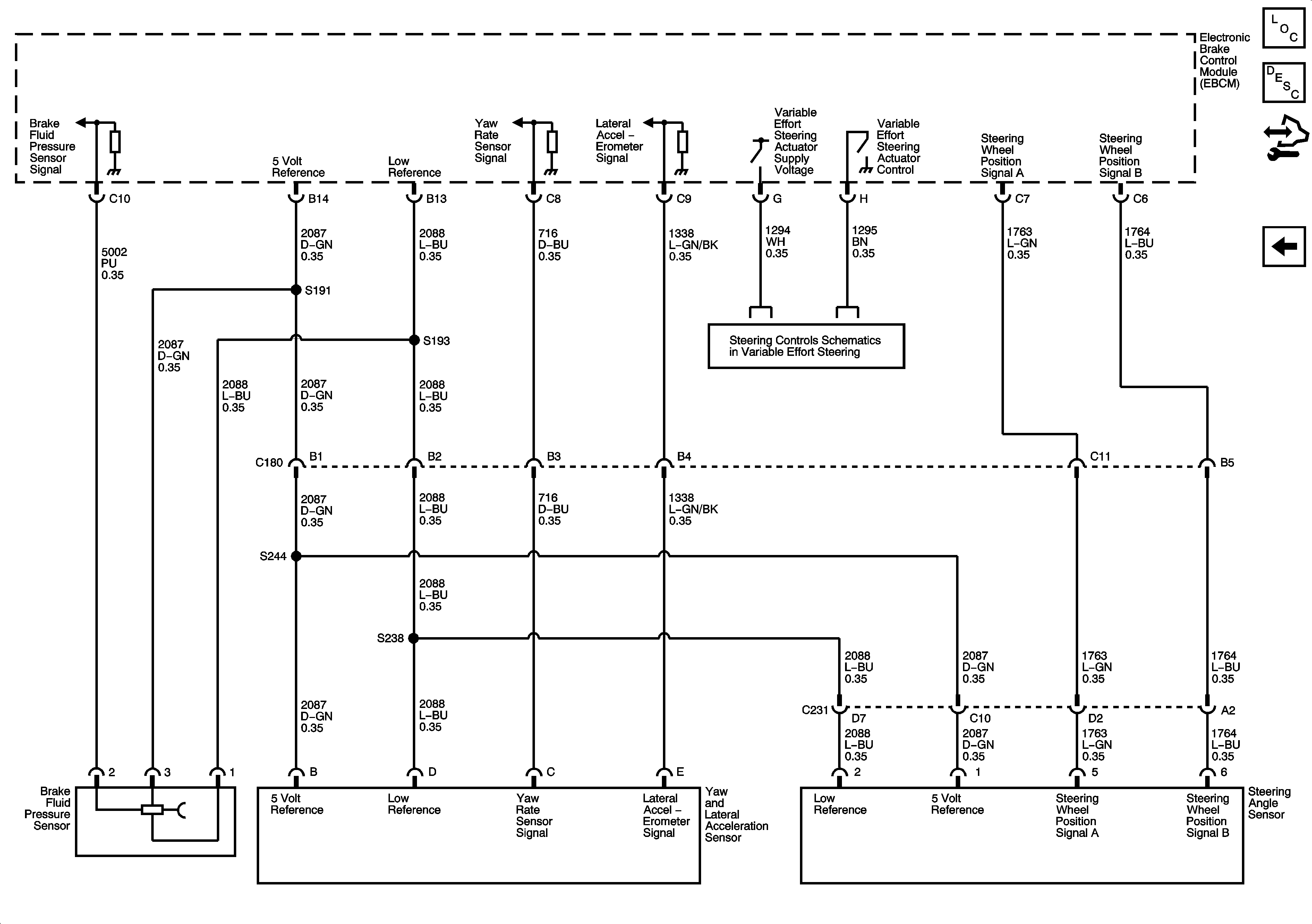
Figure
4:
Stability Control Sensors
Master Electrical Component List
ABS Description and Operation
Control Module References
Brake Pedal Signal and Traction Control Switch
Steering Controls
Antilock Brake System Schematic Icons