Tools Required
| • | J 33432-A Transverse Spring Compressor |
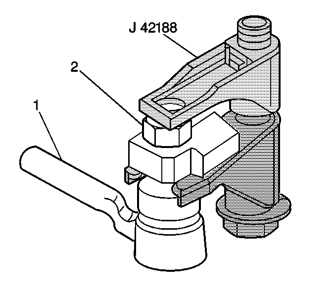
| • | J 42188 Ball Joint Separator |
Removal Procedure
- Raise and support the vehicle. Refer to Lifting and Jacking the Vehicle .
- Remove the tire and wheel assemblies. Refer to Tire and Wheel Removal and Installation .
- If the transverse spring is to be replaced, measure the front spring adjuster bolt gap (1).
- Install the J 33432-A to the transverse spring.
- Compress the transverse spring.
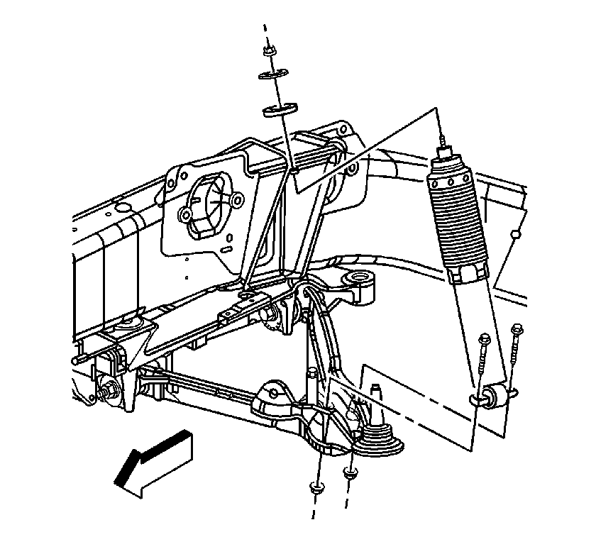
- Remove the lower shock absorber mounting bolts from one of the lower control arms.
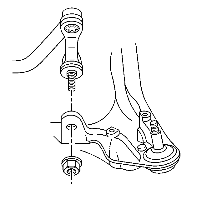
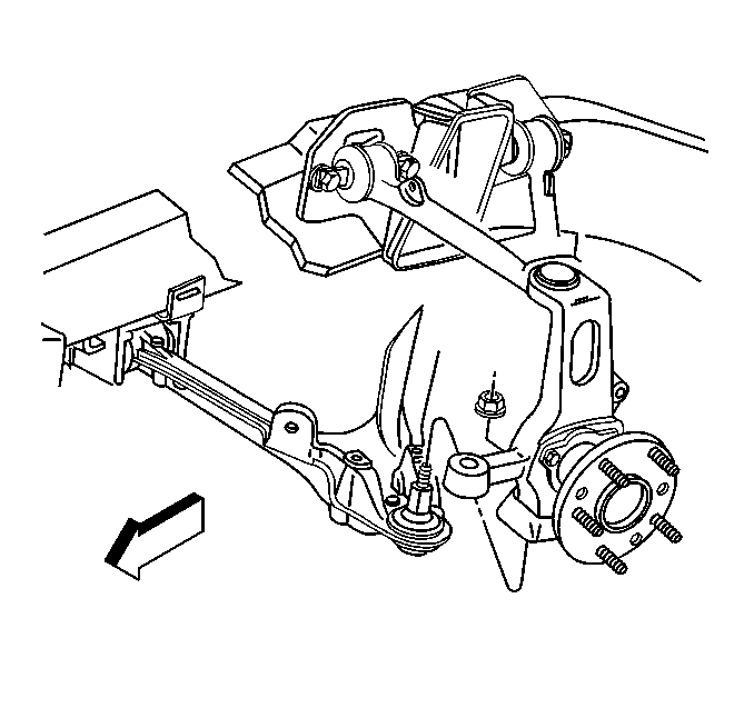
- Disconnect the stabilizer shaft link from the lower control arm.
- Loosen the lower ball joint stud nut (2) on the lower control arm. Do not remove the nut.
- Separate the lower ball joint from the steering knuckle using J 42188 .
- Remove the J 42188 .
- Remove the lower ball joint stud nut and discard.
- Support the lower control arms with jackstands.
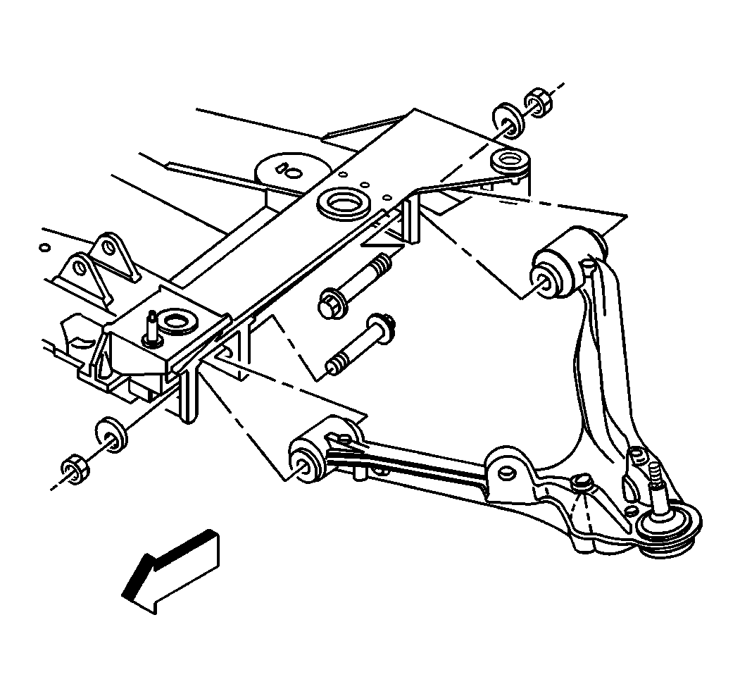
- Mark the position of the cam bolts for reference at reinstallation.
- Remove the cam bolts from the lower control arm.
- Remove the lower control arm.
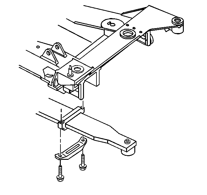
- Remove the transverse spring bolts and retainers.
- Discard the old transverse spring bolts.
- Remove the transverse spring from the vehicle.
- Remove the transverse spring compressor from the transverse spring, if the spring is to be replaced.
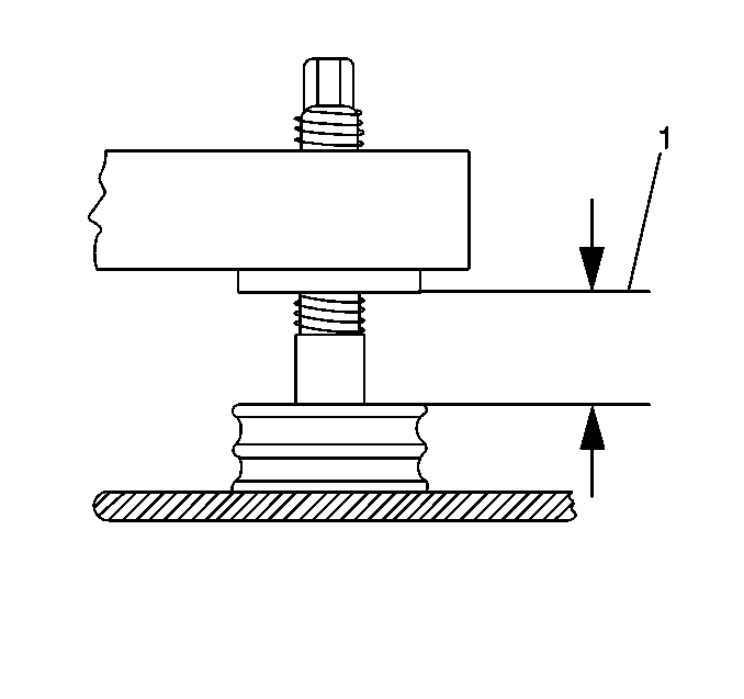
This measurement will be used in the installation procedure to setup the vehicle trim height.
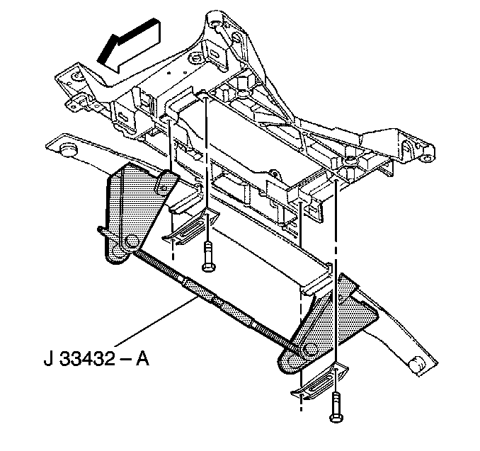
Notice: During this procedure, use care not to scratch the transverse spring.
Installation Procedure
- Install the J 33432-A to the transverse spring.
- Install the transverse spring to the crossmember.
- Install the transverse spring retainers and bolts, use new bolts, to the crossmember.
- Install the lower control arm to the front crossmember.
- Install the cam bolts to the position that was marked during disassembly.
- Install the lower control arm ball joint stud to the steering knuckle.
- Support the lower control arm with a jackstand.
- Install the shock absorber lower mounting bolts.
- Connect the stabilizer shaft link to the lower control arm.
- Remove the J 33432-A from the transverse spring.
- Remove the jackstands from the lower control arms.
- Install the tire and wheel assemblies. Refer to Tire and Wheel Removal and Installation .
- Adjust the front trim height. Refer to Trim Height Specifications .
- Perform a front wheel alignment. Refer to Wheel Alignment Measurement .

Notice: Refer to Fastener Notice in the Preface section.

Notice: Do not remove the transverse leaf spring compressor tool until after the shock absorber has been installed. The pad on the transverse leaf spring bolt could move out of position resulting in damage to the pad or a rattle in the suspension.
Tighten
Tighten the transverse spring retainer bolts, use new bolts to 62 N·m (46 lb ft).

Due to a required wheel alignment, tighten the cam bolts but do not set to the final torque specification at this time.

Tighten
Tighten the lower control arm ball joint stud nut to 30 N·m (22 lb ft) plus 180 degrees.

Tighten
Tighten the shock absorber lower mounting nuts to 28 N·m (21 lb ft).

Tighten
Tighten the stabilizer link nut to 72 N·m (53 lb ft).

